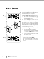
1
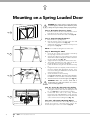
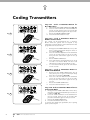
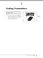
Mounting on a Spring Loaded Door
WARNING: The opener must be securely fastened to
structural supports, otherwise opener failure may ensue
causing serious personal injury and/or property damage.
Centre of Door
Step 7 - Determine the Door’s Centre
a.
fig 14
b.
Find the centre of the door and mark this location
both above the door and on top of the door.
Draw two lines 21.5mm either side of this (Fig. 14).
Step 8 - Prepositioning the Opener
a.
b.
c.
Raise the door to open position.
Rest the opener on the top edge of the door with
end of the rail against the wall (Fig. 15).
Support the drive unit level with the lowest point of
the open door (Fig. 15).
NOTE: Do not slide rail along the face of the door.
Step 9 - Mounting the C-Rail
a.
fig 15
Step
ladder
b.
c.
d.
e.
C rail
f.
Highest point
of door travel
fig 16
Door
Step
ladder
g.
h.
Close the door slowly. The rail will be elevated by
the top edge of the door as it moves.
Stop the door when it is at its highest point of travel.
Allow 25mm additional height for clearance between
the door and the track (Fig. 16).
Support the Rail in this position and close the door
The height determined in Step 10(b) will be the
height at which to mount the wall bracket.
Centre the bracket along the line determined in Step
8.
Using the bracket as a template, mark a minimum of
two holes and drill with appropriate size bit. For a
more secure fitting, the wall bracket can be anchored
using more than two holes.
Secure the bracket to the wall using:
IF CONCRETE OR BRICK - 8mm (5/6”) loxins/dynabolts.
IF TIMBER - wood screw #20 or similar (min. 50mm)
Attach the bracket and C-Rail with supplied pins (Fig. 12).
WARNING: Make sure concrete, brick wall or
timber lintels are solid and sound so as to form a
secure mounting platform.
Step 10 - Secure the drive unit to the Ceiling
Drill hole at centre of
track (recommended
bolt size M6 or M8)
a.
b.
fig 17
Ceiling
Secure the perforated angle (not supplied) to the
ceiling above where drive unit’s mounting holes will
be. See (Fig.19) for a representative mounting.
Connect the drive unit to the ceiling mounted
perforated angle with M8x20mm screws and nuts.
Strips should not extend more than 18mm below
centre of drive unit’s mounting holes (Fig. 13).
Step 10.1 - Alternative Mounting Option
Aluminium rail
Shuttle VP2 assembly
16
GDO-9 Owner Installation Instructions
The opener can be fastened to the roof by driving a bolt
through the C-Rail into a structural timber support. The
bolt head’s height must not exceed 6mm (Fig. 17).