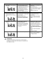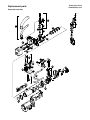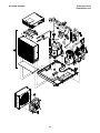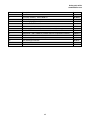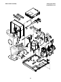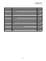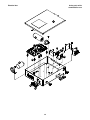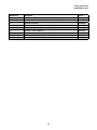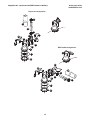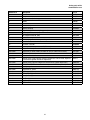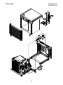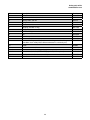
1
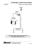
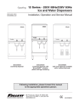
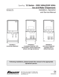
HCE/HME700A, HCE/HME700W, Ice Machines
230 V/50 Hz (Self-contained)
Order parts online
www.follettice.com
Operation and Service Manual
Following installation, please forward this manual
to the appropriate operations person.
801 Church Lane • Easton, PA 18040, USA
Toll free (877) 612-5086 • +1 (610) 252-7301
www.follettice.com
01021674R02
CAUTION!
• This appliance should be permanently connected by a qualified person in accordance with application codes.
• If the supply cord is damaged, it must be replaced by the manufacturer, its service agent or similarly qualified
persons in order to avoid a hazard.
• Connect to potable water supply only.
• This appliance can be used by children aged 8 years and above and persons with reduced physical, sensory,
or mental capabilities, or lack of experience and knowledge if they have been given supervision or instruction
concerning use of the appliance in a safe way and understand the hazards involved. Children should be
supervised to ensure that they do not play with the appliance.
• This appliance is intended to be used for household and similar applications such as staff kitchen areas
in shops, offices and other working environments; farm houses and by clients in hotels, motels and
other residential type environments; bed and breakfast type environments; catering and similar non-retail
applications.
• WARNING! To avoid a hazard due to instability of the appliance, it must be fixed in accordance with the
instructions.
• Warranty does not cover exterior or outside installations.
• Moving parts. Do not operate with front cover removed.
• Hot parts. Do not operate with cover removed.
• To reduce risk of shock, disconnect power before servicing.
• To prevent circuit breaker overload, wait 15 minutes before restarting this unit. This allows the compressor to
equalize and the evaporator to thaw.
• Drain line must be vented.
• Water supply must be treated by a scale-inhibiting filter.
• Most ice machine cleaners contain citric or phosphoric acid, which can cause skin irritation. Read caution
label on product and follow instructions carefully.
• Ice is slippery. Maintain counters and floors around dispenser in a clean and ice-free condition.
• Ice is food. Follow recommended cleaning instructions to maintain cleanliness of delivered ice.
2
Table of contents
Welcome to Follett Corporation ............................................................................................................................ 4
Specifications ......................................................................................................................................................... 5
Operation................................................................................................................................................................. 7
Cleaning .......................................................................................................................................................... 7
Weekly exterior care ................................................................................................................................. 7
Monthly condenser cleaning .................................................................................................................... 7
Semi-annual evaporator cleaning .................................................................................................................... 7
Service ................................................................................................................................................................... 12
Ice machine operation ................................................................................................................................... 12
Water system ................................................................................................................................................. 13
Electrical system............................................................................................................................................ 14
Normal control board operation.............................................................................................................. 14
Error faults .............................................................................................................................................. 15
Hard error ............................................................................................................................................... 15
Soft errors ............................................................................................................................................... 15
Relay output indication ........................................................................................................................... 15
Compressor/refrigerant solenoid output ................................................................................................. 15
Wiring diagram ....................................................................................................................................... 16
Compressor data .................................................................................................................................... 17
Gearmotor data ...................................................................................................................................... 17
Resistance of windings .......................................................................................................................... 17
Mechanical system ................................................................................................................................. 18
Evaporator disassembly ......................................................................................................................... 18
Evaporator reassembly ........................................................................................................................... 21
Refrigeration system ...................................................................................................................................... 25
Refrigeration pressure data .................................................................................................................... 25
Refrigeration system diagram................................................................................................................. 25
Refrigerant charge size .......................................................................................................................... 26
Refrigerant replacement requirements ................................................................................................... 26
Evacuation .............................................................................................................................................. 26
Ambients ................................................................................................................................................ 26
Ice capacity test ..................................................................................................................................... 26
Bin full detection system ................................................................................................................................ 27
Troubleshooting ............................................................................................................................................. 28
Replacement parts ........................................................................................................................................ 30
3
Welcome to Follett
Follett equipment enjoys a well-deserved reputation for excellent performance, long-term reliability and
outstanding after-the-sale support. To ensure that this equipment delivers the same degree of service, we ask
that you review the installation manual (provided as a separate document) before beginning to install the unit.
Our instructions are designed to help you achieve a trouble-free installation. Should you have any questions or
require technical help at any time, please call our technical service group at (877) 612-5086 or +1 (610) 2527301.
Before you begin
After uncrating and removing all packing material, inspect the equipment for concealed shipping damage. If damage
is found, notify the shipper immediately and contact Follett Corporation so that we can help in the filing of a claim,
if necessary.
Check your paperwork to determine which model you have. Follett model numbers are designed to provide information
about the type and capacity of Follett equipment. Following is an explanation of the different model numbers in the
Horizon 700 series.
Chewblet® Ice Machine Model Number Configurations
HC
Machine
MC Maestro™
Chewblet
(400 Series)
HC Horizon
Chewblet
(1000, 1400,
1650 Series)
HM Horizon
Micro
Chewblet
C
700
Voltage
Series
C 208-230/60/1 (icemaking head) 400 up to
Self-contained only.
454 lbs
D 115/60/1 (icemaking head)
(206kg)
Self-contained and remote.
700 up to
If remote unit, high side is
750 lbs
208-230/60/1.
(340kg)
1000 up to
E 230/50/1 (icemaking head)
Self-contained only.
1036 lbs
(471kg)
F 115/60/1 (icemaking head)
Remote only. High side is
1400 up to
208-230/60/3.
1450 lbs
(658kg)
1650 up to
1580 lbs
(717kg)
A
V
S
Condenser
A Air-cooled, self-contained
W Water-cooled,
self-contained
R Air-cooled, remote
condensing unit
N Air-cooled, no condensing
unit for
connection to parallel rack
system
4
Application
V Vision™
H Harmony™
B Ice storage
bin
J Drop-in
M Ice Manager™
diverter valve
system
Configuration
S RIDE®
(RIDE remote ice
delivery equipment)
T
Top-mount
Specifications
Electrical
Each ice machine requires its own separate circuit with electrical disconnect within 10 ft (6m).
Equipment ground required.
Standard electrical:
HCE/HME700: 230/50/1 (6 ft (2m) cord
Maximum ice machine fuse – 15A each
Amperage: 7A
Plumbing
3/8"
3/4"
1/4"
1/4"
OD push-in water inlet
MPT drain
FPT condenser inlet (water-cooled condenser only)
FPT condenser drain (water-cooled condenser only)
Notes: 3/4" vented drain line must slope a minimum of 1/4" per foot (6mm per 30.4cm run).
Drain to be hard piped and insulated.
To prevent back flow, do not connect drains.
Separate drains for ice machine and condenser.
Water shut-off recommended within 10 feet (3m).
Water supply must be treated by a scale-inhibiting filter (Follett item# 00130286).
Ambient
Air temperature
Water temperature
Water pressure – potable
Note:
100 F/38 C max.
90 F/32 C max.
70 psi max. (483 kPa)
50 F/10 C min.
45 F/7 C min.
10 psi min. (89 kPa)
Water-cooled condenser pressure 150 psi (1034 kPa)
Heat rejection
Air-cooled rejects 8850 BTU/hr
Water-cooled rejects 10150 BTU/hr
Ice production
Note: Water regulating valve set to maintain a 215 PSIG (95°F Saturated R404A) discharge pressure at all
conditions.
Air-cooled ice machine capacity/24 hrs.
60
16
651
295
620
281
572
259
569
258
537
244
70
21
600
272
574
260
538
244
519
235
504
229
80
27
571
259
531
280
506
230
493
224
471
214
90
32
518
235
492
223
479
217
452
205
430
195
100
38
460
209
443
201
416
189
415
188
389
176
lbs
kg
lbs
kg
lbs
kg
lbs
kg
lbs
kg
Potable Make-up Water Temperature F/C
Inlet Water Temperature F/C
F
C
50
10
60
16
70
21
80
27
90
32
Water-cooled ice machine capacity/24 hrs.
Ambient Air Temperature F/C
Ambient Air Temperature F/C
F
C
50
10
60
16
70
21
80
27
90
32
60
16
608
276
578
262
554
251
530
240
515
234
5
70
21
600
272
571
259
540
245
521
236
512
232
80
27
592
269
567
257
537
244
514
233
508
230
90
32
583
264
548
249
528
239
489
222
484
220
lbs
kg
lbs
kg
lbs
kg
lbs
kg
lbs
kg
Dimensions and clearances
Entire front of ice machine must be clear of obstructions/connections to allow removal.
1" (26mm) clearance above ice machine for service.
1" (26mm) minimum clearance on sides.
The intake and exhaust air grilles must provide at least 160 sq in (1032 sq cm) of open area.
Air-cooled model HCE700A ice machines – 18" (458mm) minimum clearance between discharge and air
intake-grilles.
ICE TRANSPORT HOSE CONNECTION
22.44" (57 cm)
1.75 MIN.
AIR EXHAUST
22.46" (57 cm)
21.25"
(54 cm)
3/8"OD PUSH-IN WATER INLET
3/4" MPT DRAIN
6
1/4" FPT CONDENSER
(WATER COOLED ONLY)
Operation
Cleaning and preventive maintenance (all models)
Note:
Do not use bleach to sanitize or clean the icemaker.
Preventive maintenance
Periodic cleaning of Follett’s icemaker system is required to ensure peak performance and delivery of clean,
sanitary ice. The recommended cleaning procedures that follow should be performed at least as frequently as
recommended, and more often if environmental conditions dictate.
Cleaning of the condenser can usually be performed by facility personnel. Cleaning of the icemaker system,
in most cases, should be performed by your facility’s maintenance staff or a Follett authorized service agent.
Regardless of who performs the cleaning, it is the operator’s responsibility to see that this cleaning is performed
according to the schedule below. Service problems resulting from lack of preventive maintenance will not be
covered under the Follett warranty.
Weekly exterior care
The exterior may be cleaned with a stainless cleaner such as 3M Stainless Steel Cleaner & Polish or equivalent.
Monthly condenser cleaning (air-cooled icemaker only)
1. Use a vacuum cleaner or stiff brush to carefully clean condenser coils of air-cooled icemakers to ensure
optimal performance.
2. When reinstalling counter panels in front of remote icemakers, be sure that ventilation louvers line up with
condenser air duct.
Semi-annual evaporator cleaning (every 6 months)
WARNING
• Wear rubber gloves and safety goggles (and/or face shield) when handling ice machine cleaner or sanitizer.
CAUTION
• Use only Follett approved SafeCLEAN™ Cleaner (part #00132001) and NU-CALGON IMS-II SANITIZER
(00979674).
• Do not mix Cleaner and Sanitizer solutions together.
• DO NOT USE BLEACH.
• It is a violation of Federal law to use these solutions in a manner inconsistent with their labeling.
• Read and understand all labels printed on packaging before use.
Note: Complete procedure for cleaning an sanitizing MUST be followed. Ice must be collected for
10 minutes before putting ice machine back into service.
1. To clean – Remove cover. Press the CLEAN button.
The machine will drain. Wait for the LO WATER light
to come on (Fig. 1).
Fig. 1
LO WATER
7
Fig. 2
2. Mix 1 gallon (3.8L) 120 F (49 C) water and
7 ounces (198g) (one 7 ounce packet of Follett
SafeCLEAN ice machine cleaner, part# 00132001).
Locate cleaning cup. Fill until CLEANER FULL light
comes on (Fig. 2).
Note: Do not use bleach to sanitize or clean the
icemaker.
CLEANER
FULL
Fig. 3
3. Replace cover on cleaning cup. Wait until machine
restarts. Machine will clean, then flush 3 times in
approximately 15 minutes (Fig. 3).
15
Fig. 4
4. To sanitize – Press CLEAN button. The machine
will drain. Wait for LO WATER light to come on
(Fig. 4).
LO WATER
8
5. Mix 1 gallon 120 F (49 C) water and 1.6 ounces
(48ml) NU-CALGON IMS-II SANITIZER. Fill until
CLEANER FULL light comes on (Fig. 5).
Place one Sani-Sponge™ in remaining sanitizing
solution and retain for Step 9.
Note: Do not use bleach to sanitize or clean the
icemaker.
Fig. 5
6. Replace cover on cleaning cup. Wait until machine
restarts. Machine will sanitize, then flush 3 times in
approximately 15 minutes (Fig. 6).
Fig. 6
CLEANER
FULL
15
Fig. 7
7. Disconnect coupling as shown (Fig. 7).
Note: Steps 8-11 must be completed before
machine flushes and starts producing ice.
9
8. Using disposable food service grade gloves, insert
dry Sani-Sponge™ (kit part# 00132068). Next,
insert Sani-Sponge soaked in Nu-Calgon IMS-II
sanitizer solution (from Step 5). Push both SaniSponges down ice transport tube with supplied
pusher tube (Fig. 8).
Fig. 8
(40 16"
7m
m)
1
2
3
Fig. 9
9. Remove and discard 16" (407mm) pusher tube
(Fig. 9).
Fig. 10
10. Reconnect coupling. When sanitizing cycle ends,
machine will start producing ice. Press power
switch ON. Ice pushes Sani-Sponges through tube
(Fig. 10).
10
11. Place a sanitary (2 gallon or larger) container in
bin or dispenser to collect Sani-Sponges and ice
for 10 minutes. Collect 5.5 lbs (3kg) of ice from unit.
Discard ice and Sani-Sponges (Fig. 11).
11
Fig. 11
Service
Ice machine operation (all models)
Follett’s ice machine consists of five distinct functional systems covered in detail as follows:
• Water system
• Electrical control system
• Mechanical assembly
• Refrigeration system
• Bin full
The Horizon ice machine overview
The Follett Horizon ice machine uses a horizontal, cylindrical evaporator to freeze water on its inner surface. The
refrigeration cycle is continuous; there is no batch cycle. The evaporator is flooded with water and the level is
controlled by sensors in a reservoir. A rotating auger (13 RPM) continuously scrapes ice from the inner wall of the
evaporator. The auger moves harvested ice through the evaporator into an ice extrusion canal. The ice is forced
through a restrictive nozzle that squeezes out the water and creates the Chewblet. The continuous extrusion process
pushes the Chewblets through a transport tube into a dispenser or bin.
A solid state PC board controls and monitors the functionality of the ice machine. In addition to sequencing electrical
components, the board monitors various operational parameters. A full complement of indicator lights allows visual
status of the machine's operation. Additionally, the PC board controls the self-flushing feature of the ice machine. The
evaporator water is periodically drained and replenished to remove minerals and sediment.
A unique “bin full” detection system is incorporated in the Horizon ice machine. A switch located at the ice discharge
port of the machine detects the position of the transport tube. When the bin fills up with ice, the transport tube
moves out of the normal running position, and the switch turns the ice maker off. A domed housing at the end of the
transport tube contains the ice extrusion loads during shut down.
Harvest system diagram
Ice Transport Tube
Water Inlet
Compression
Nozzle
Auger
12
Water system
The water level in the evaporator is controlled by a feed solenoid and level detecting sensors. Referencing the
diagram below, water sensing rods extend down into the reservoir at the end of the evaporator assembly. The
system works via electrical conductivity as follows:
One of the longest probes is a common. When water is between any of the other probes and the common, the
PC board will sense the activation. During normal operation, the water level rises and falls between the Normal
High and Normal Low sensors. As water is consumed to make ice, the level will fall until the Normal Low sensor
is exposed, triggering the water feed solenoid on. Water will fill until the Normal High sensor is activated.
Note: The potable water dissolved solids content must be greater than 10 ppm for the water control system to
function properly. If using reverse osmosis water filtration system, ensure T.D.S level is greater than 10
ppm.
Water system diagram
13
NORMAL HI
ALARM LO
COMMON
NORMAL
OPERATING
RANGE
NORMAL LO
Water level diagram
Electrical system
ATTENTION!
To prevent circuit breaker overload, wait 15 minutes before
restarting this unit. This allows the compressor to equalize and
the evaporator to thaw.
Normal control board operation
The PC board indicator lights provide all the information necessary to determine the machine's status. Green
indicator lights generally represent “go” or normal operation; Yellow indicators represent normal off conditions;
Red indicators generally represent alarm conditions, some of which will lock the machine off.
A flashing green light labeled POWER indicates power to the machine. All other normal operation status
indicators are covered as follows:
Ice machine disposition
Legend:
1.
ON
Operating conditions
OFF
Ice machine is making ice.
ON or OFF
FLASHING
1.
Normal running.
.
2. Ice machine is not making ice.
2. Normal time delay. When the bin fills with ice, the LOW
BIN light goes out momentarily and the refrigeration
and auger drive systems immediately shut down. (Note:
The fan motor will continue to run for 10 minutes to cool
condenser) The TIME DELAY light comes on, initiating
the time delay period. When the time delay expires, the
machine will restart provided that the LOW BIN light is on.
Note: The ice machine has a 15-minute startup delay
when power is applied to prevent circuit overload.
DIP Switch Settings
14
Error faults:
The Horizon PC board monitors various operating parameters including high pressure, auger gearmotor
amperage limits, clogged drain, and low water alarm conditions. There are two types of errors namely “hard” or
“soft”. A hard error is one that shuts the machine off and will not allow restart until the reset button is pressed.
Even cycling power will not reset a hard error. A soft error can either be automatically reset should the condition
rectify, or if power is cycled. Should an error occur, consult the troubleshooting guide in this manual or a Follett
service technician.
Soft errors:
HI AMPS: The PC board monitors the amperage of the auger motor. Should the gear motor experience current
draw above the allowable limit, the machine will shut down and the TIME DELAY and HI AMP will be illuminated.
After the time delay the machine will restart and the TIME DELAY and HI AMP will clear.
LO WATER: During operation, the water level cycles between the normal low and normal high sensors. Should
the water be shut off to a running machine, a soft error will occur. The error sequence is as follows: During
operation, the water level falls to the normal low sensor, and when it does the water feed solenoid is energized.
If water is not detected at the normal low sensor within 10 seconds, a soft error will occur. The machine will shut
down, but the water feed solenoid will remain energized. Should water return, it will fill to the normal low sensor
and the machine will resume normal operation. The error will clear automatically.
HI PRESSURE: Should the refrigeration pressure rise above 425 psi, the machine will shut down and the TIME
DELAY and HIGH PRESSURE will be illuminated. After the time delay, and if the pressure has fallen back below
the reset point of 295 psi, the machine will restart and the TIME DELAY and HIGH PRESSURE will clear.
Hard error:
DRAIN CLOG: The drain clog sensor, located in the chassis, underneath the rear drain pan, will detect the
presence of water just below the top edge of the pan. If water does not properly flow out of the drain pan it will
overflow into the chassis and rise to the sensor (especially during a self-flushing purge cycle). Pressing the reset
button will restart the ice machine.
Relay output indication:
Each relay on the board has an indicator light associated with its output. For example, when the relay for the
water feed solenoid is energized, the adjacent indicator light glows green.
Flushing logic
Flush on fly: For every one (1) hour of ice making time, the machine will open the drain valve for a duration of
60 seconds. While the drain valve is open, the machine will continue to make ice and the water feed valve will
cycle to maintain water level.
Off cycle: At the completion of off-cycle time delay, the machine checks for a cumulative one (1) hour of ice
making time since the last off-cycle flush. If the cumulative ice making time exceeds one (1) hour, the machine
will open the drain valve for 60 seconds to drain the evaporator in its entirety. It will then refill with water and
begin making ice. If the ice making time is less than 1 hour, the machine will start and begin making ice
without draining the evaporator.
15
16
WHITE OR
GRAY
AUGER
BLACK
BLUE OR
PINK
RESERVOIR
WATER SENSOR
DRAIN CLOG
SENSOR
BIN
MAINT.
CLEAN
HIGH
PRESS
CLEANER FULL
DRAIN CLOG
HI PRESSURE
HI AMPS
SERVICE
MAINT/CLEAN
LOW WATER
TIME DELAY
SLEEP CYCLE
MAKING ICE
LOW BIN
POWER
Wiring diagram
Compressor data
Compressor current draw at 230 VAC
Air/Water-cooled
60 F/15.5 C
4.13A
70 F/21.1 C
4.06A
Locked rotor amps: 31A @ 230V
Gearmotor data
Gearmotor current: 0.53A @ 230V
Gearmotor torque-out (high amp) trip point: 0.9A @ 230V
Locked rotor amps: 1A @ 230V
Resistance of windings
230 vac gearmotor (Brother):
White to black: 62Ω
White to tan: 62Ω
Tan to black: 124Ω
Compressor start winding (230V)
5.95Ω
Compressor run winding (230V)
0.69Ω
Fan motor
38Ω
Fan motor data
Fan motor current
0.75A @ 230V
17
80 F/26.7 C
4.08A
90 F/32.2 C
4.10A
100 F/37.8 C
4.45A
Fig. 12
Mechanical System
Evaporator disassembly
1. Press CLEAN button to purge evaporator. Turn
power OFF when LO WATER lights.
2. Unscrew and disconnect transport tube from
louvered docking assembly.
Fig. 13
3. Unplug gear motor.
Fig. 14
4. Remove shuttle housing:
§ Remove vent tube (Fig. 14.1).
§ Disconnect shuttle housing switch connections
(Fig. 14.2).
§ Remove two screws and lift shuttle housing (Fig. 14.3).
§ Remove stream divider (Fig. 14.4).
3
2
1
4
18
Fig. 15
5. Remove gear motor:
§ Remove gear motor insulation (Fig. 15.1).
§ Remove 1/4-20 screw, retainer, and spacer (Fig. 15.2).
§ Remove two 1/2" bolts (Fig. 15.3).
§ Pull gear motor from auger (Fig. 15.4).
§ Remove main housing insulation (Fig. 15.5).
6. Remove all traces of petro-gel from auger shaft.
4
5
3
2
3
1
Fig. 16
7.
Remove main housing:
§ Use an allen wrench to remove 3/16" allen screws (3)
(Fig. 16.1).
§ Remove shaft insulation (Fig. 16.2).
§ Remove main housing (Fig. 16.3).
3
1
1
2
1
Fig. 17
8. Remove and discard mating ring and seal
(Fig. 17.1).
9. Carefully remove auger (Fig. 17.2).
WARNING!
1
Use caution when removing auger. The auger is
very sharp - handle with care to avoid personal
injury.
2
1
19
Fig. 18
10. Press the lever on the back of the reservoir
(Fig. 18.1) to release and remove the solenoid
(Fig. 18.2).
1
2
Fig. 19
11. Remove three screws to remove the reservoir
insulation (Fig. 19).
Fig. 20
12. Remove three screws to remove the reservoir
(Fig. 20).
20
Fig. 21
13. To remove the rear bushing, place the auger into the
evaporator and use it to gently tap and dislodge the
rear bushing housing (Fig. 21).
Evaporator reassembly
Fig. 22
1. Remove and inspect O ring seal. Replace if
damaged in any way.
2. Place rear bushing into evaporator.
3. Install the three bolts: partially tighten each bolt,
alternating bolts until the rear bushing is fully seated
and properly aligned (Fig. 22).
4. When fully seated, remove the bolts.
Fig. 23
5. Install the reservoir with three bolts (Fig. 23).
21
Fig. 24
6. Install the reservoir insulation, tube clamp, and
solenoid lever with three screws.
7.
Install solenoid.
Fig. 25
1. Remove and inspect O ring seal. Replace if
damaged in any way (Fig. 25.1).
2. Clean O ring groove. Lubricate O ring with petrol-gel
and reinstall (Fig. 25.2).
2
1
Fig. 26
3. Use cardboard disc to press new mating ring into
main housing (Fig. 26.1).
4. Lube the shaft with liquid soap in the area shown
(Fig. 26.2) and slip on seal and spring (Fig. 26.3).
Note: Do not touch the sealing surfaces with bare
hands. Contact with bare skin will cause
premature seal failure.
5. Install auger (Fig. 26.4).
1
Cardboard
disc
Do NOT
touch!
2
3
22
4
Fig. 27
6. Install main housing:
§ Slide main housing onto auger shaft (Fig. 27.1).
§ Install main housing insulation (Fig. 27.2).
§ Use an allen wrench to install 3/16" allen screws (3)
(Fig. 27.3).
1
3
3
2
3
Fig. 28
7.
Apply a coat of petrol-gel to the auger shaft.
8. Install gear motor:
2
§ Install main housing insulation (Fig. 28.1).
§ Slide gear motor onto the auger shaft (Fig. 28.2).
§ Install two 1/2" bolts (Fig. 28.3).
1
3
3
Fig. 29
9. Use screwdriver to orient auger shaft to align with
motor shaft keyway (Fig. 29.1).
10. Install key into keyway (Fig. 29.2).
2
1
Fig. 30
11. Install spacer, ensure that key is captured in slot
(Fig. 30.1)
1
23
Fig. 31
12. Insert screwdriver into groover of auger shaft and
pry shaft outwards (Fig. 31.1).
13. Insert retainer into groove (Fig. 31.2), ensure that
retainer is aligned with hole in spacer.
1
2
Fig. 32
14. Install screw and tighten (Fig. 32.1).
1
2
Fig. 33
15. Install gear motor insulation.
24
Fig. 34
16. Install shuttle housing:
§ Install stream divider (Fig. 34.1).
§ Place shuttle housing and install two screws
(Fig. 34.2).
§ Plug in shuttle housing connections (Fig. 34.3).
§ Connect vent tube (Fig. 34.4).
NO
CONNECT
2
BLACK
ORANGE
3
4
1
Fig. 35
17. Plug in gear motor.
BR
§ BROWN to BLUE
§ BLACK to BLACK
§ WHITE to GRAY
OW
Nt
oB
BLA
CK
WH
Fig. 36
18. Connect transport tube to louvered docking
assembly.
25
ITE
LU
E
to
B
LA
CK
to
G
RA
Y
Refrigeration system
Refrigerant pressure data
Air-cooled condensers (air)
60 F/16 C
70 F/21 C
80 F/27 C
90 F/32 C
100 F/38 C
190/31
220/33
250/35
285/37
315/40
60 F/16 C
70 F/21 C
80 F/27 C
90 F/32 C
215/29
215/31
215/33
215/35
Pressure (psig)
discharge/suction
Water-cooled condensers (water)
Pressure (psig)
discharge/suction
Note:
The water control valve is factory set to maintain 215 ± 15 psi discharge pressure @ 70 F/21 C water.
Refrigeration system diagram
HIGH SIDE
REFRIGERATION
LINE RUN
HIGH SIDE
SERVICE PORT
LOW SIDE
SERVICE PORT
FILTER-DRIER
CONDENSER
HEAT
EXCHANGER
LOW SIDE
REFRIGERATION
LINE RUN
THERMOSTATIC
EXPANSION
VALVE
COMPRESSOR
HIGH PRESSURE VAPOR
HIGH PRESSURE LIQUID
LOW PRESSURE LIQUID
26
LOW PRESSURE VAPOR
Refrigeration charge
All service on refrigeration systems must be performed in accordance with all federal, state and local laws. It is the
responsibility of the technician to ensure that these requirements are met. Recharging ice machine to other than
factory specifications will void the warranty.
R404A ice machine charge specifications
Model
Charge
Refrigerant type
HCE700A (air-cooled)
19 oz (539g)
R404A
HCE700W (water-cooled)
15 oz (425g)
R404A
Refrigerant replacement requirements
1. Non-contaminated refrigerant removed from any Follett refrigeration system can be recycled and
returned to the same system after completing repairs. Recycled refrigerant must be stored in a clean,
approved storage container. If additional refrigerant is required, virgin or reclaimed refrigerant that
meets ARI standard 700-88 must be used.
2. In the event of system contamination (for example, a compressor burn out, refrigerant leak, presence of
non-condensibles or moisture), the system must be repaired, evacuated and recharged using virgin or
reclaimed refrigerant that meets ARI standard 700-88.
3. Follett Corporation does not approve of recovered refrigerants. Improper refrigeration servicing
procedures will void the factory warranty.
Evacuation
Evacuate the system to a level of 500 microns. When the 500 micron level is reached, close all valves. Allow the
system to sit for approximately 20 minutes. During this period the system pressure should not rise. If the system
pressure rises and stabilizes there is moisture in the system and further evacuation is needed. If the pressure
continues to rise check the system for leaks.
Ambients
Air temperature1
Water temperature2
Minimum
50 F/10 C
45 F/7 C
Maximum
100 F/37.8 C
90 F/32.2 C
1Ambient air temperature is measured at the air-cooled condenser coil inlet.
2Ambient water temperature is measured in the ice machine water reservoir.
Ice capacity test
Ice machine production capacity can only be determined by weighing ice produced in a specific time period.
1.
2.
3.
4.
5.
6.
7.
8.
Replace all panels on ice machine.
Run ice machine for at least 15 minutes.
Weigh and record weight of container used to catch ice.
Catch ice for 15 or 20 minutes.
Weigh harvested ice and record total weight.
Subtract weight of container from total weight.
Convert fractions of pounds to decimal equivalents (ex. 6 lbs 8oz = 6.5 lbs).
Calculate production using following formula:
1440 min. x wt. of ice produced
Total test time in minutes
=
Production capacity/24 hr.
9. Calculated amount per 24 hours should be checked against rated capacity for same ambient and water
temperatures in Ice Production Tables.
27
“Bin full” detection system
The Follett Horizon ice machine incorporates a unique “bin full” detection system that consists of the shuttle and
actuator. The shuttle incorporates a flag and switch. Referencing the figure below, the normal running position
of the flag is down, and the switch is closed. When the bin fills to the top and ice can no longer move through
the tube, the machine will force the shuttle flag up, opening the switch and shutting the machine off. The shuttle
actuator, located above the ice bin allows the ice to curl up within it when the bin is full. In this way, there are no
loads generated that would tend to lift off the lid of the bin.
Shuttle flag and sensor
Running
Off
Shuttle actuator
Running
Off
28
Troubleshooting
Please see “Service” section for a description of each function.
Ice machine disposition
Legend:
1.
ON
Possible causes
OFF
Ice machine is in running
condition but not making ice.
.
ON or OFF
1.
2.
3.
4.
5.
6.
7.
Corrective action
FLASHING
Defective compressor.
Defective start relay.
Defective start capacitor.
Defective run capacitor.
Defective main contactor.
No output from PC board.
Machine in Purge cycle.
1.
2.
3.
4.
5.
6.
7.
Replace compressor.
Replace start relay.
Replace start capacitor.
Replace run capacitor.
Replace main contactor.
Replace PC board.
Check for Purge operation.
2. Machine in TIME DELAY without 1. Ice jamming due to improperly
full bin.
installed transport tube causing
a false shuttle.
2. Shuttle stuck in up position.
3. Damaged or improperly installed
thermostat (open).
4. Transport tube backed-out of
coupling.
1. Correct transport tube routing.
2. Repair or replace shuttle
mechanism.
3. Replace or reposition
thermostat.
4. Correct coupling installation.
3. Ice machine is not making ice.
HI AMPS.
1. Poor water quality causing ice to
jam auger.
2. Damaged shuttle mechanism.
3. Intermittent drive output from
PC board. Evaporator will freeze
causing a HI AMPS error.
4. Gearmotor is unplugged.
1. Clean ice machine. Increase
flushing frequency.
2. Replace or repair shuttle
mechanism.
3. Replace PC board.
4. Plug in gearmotor.
1. High ambient temperatures
>100 F (38 C).
2. Poor ventilation or air
recirculation.
3. Clogged condenser (air-cooled).
4. No water flow through condenser
(water-cooled).
5. Fan not working properly. No
air flow.
• Blocked fan blades
• No fan output from PC board
• Faulty fan motor
1. Air condition area to below
100 F (38 C).
2. Reposition ice machine or
properly ventilate. Prevent
ice machine exhaust from
recirculating.
3. Clean condenser grille (aircooled).
4. Restore water flow to condenser.
5. Correct air flow.
• Remove any blockage from
fan blades
• Replace PC board
• Replace fan motor
.
4. Ice machine is not making ice.
HI PRESSURE.
.
29
Ice machine disposition
Possible causes
Corrective action
5. Ice machine is not making ice.
Drain clog.
1. Drain hose kinked or plugged
causing water to back up.
2. Improper floor drain routing/pitch
causing water to back up.
3. High TDS levels and leaking
drain solenoid may cause an
errant drain clog.
4. No vent on external drain line.
1. Remove kink or blockage from
drain hose.
2. Re-route floor drain.
3. Clean area around drain sensor
and/or replace Drain solenoid
valve.
4. Add vent to drain line.
6. Ice machine is making ice.
Excessive water in bin or
coming into bin from transport
tube.
1. Failed water sensors. Processor
assumes there is no water when
there is water.
2. Blocked reservoir vent.
3. Defective water feed solenoid
valve. Stuck in open position.
1. Clean or replace water probe
assembly. Check wiring
connections.
2. Clean or replace vent tubes.
3. Replace water feed solenoid
valve.
7.
1. Water supply is insufficient.
2. Low water pressure.
3. Defective water feed solenoid
valve. Stuck in closed position.
4. No water feed output from
PC board.
1. Restore water supply and check
water filters. If evaporator was
completely empty the reset
button may have to be pressed
to restart the ice machine.
2. Ice machine will eventually start
when water reaches normal lo
level.
3. Replace water feed solenoid
valve.
4. Replace PC board.
1. 30,000 hour bushing check.
1. Call Follett technical service
group at (877) 612-5086 or
+1 (610) 252-7301.
.
Ice machine is not making ice.
Lo water.
8. Service required.
ATTENTION!
To prevent circuit breaker overload, wait 15 minutes before
restarting this unit. This allows the compressor to equalize and
the evaporator to thaw.
30
THIS PAGE INTENTIONALLY LEFT BLANK
31
Order parts online
www.follettice.com
Replacement parts
Evaporator assembly
3
2
30
6
1
23
4
5
13
11
8
7
10
9
17
14
15
28
21
22
19
16
20
18
17
29
26
17
25
24
12
12
32
27
Order parts online
www.follettice.com
Reference #
Description
Part #
1
Tube, ice transport, molded
01006485
2
Shuttle assembly
01006253
3
Switch, shuttle
01006261
4
Compression nozzle
01001734
5
Compression nozzle, deflector assembly
01006246
6
Gasket and retainer
00115600
7
Auger hardware (includes screw, spacer, retainer) - S/N E03141 and after
01041474
7
Auger hardware (includes washer and 2 nuts) - before S/N E03141
01006493
8
Key
00974394
9
Bolt, gearmotor mounting (1)
00974352
10
Gearmotor, 230 V (includes capacitor)
01006238
11
Main housing
01006204
12
O ring
00974329
13
Seal, auger shaft
00969592
14
Cup, sanitizer
00924035
15
Gasket, sanitizer
00124032
16
Cap, sanitizer (includes gasket)
00130880
Not shown
Tubing, water, 3/8" OD
502719
Not shown
Tubing, water, 1/4" OD
502079
17
Retainer kit, evaporator
01006535
18
Solenoid, water feed (230 V)
00116848
19
Reservoir lid and sensors
01006295
20
Clip, water shut-off valve
502922
21
Clamp, cleaning cup
00983544
22
Valve, shut-off, water
502921
23
Auger (includes seal, key, and auger hardware)
01006196
24
Evaporator (includes (2) o-rings)
01006188
25
Rear bushing housing and bushing (includes (1) o-ring)
01006279
26
Reservoir assembly, water (includes lid and insulation)
01006287
27
Solenoid, purge (230 V)
00974287
28
Tube, vent
00991786
29
Tube, sanitizer
00991778
Not shown
Insulation kit, evaporator/gear motor/reservoir
00974600
30
Kit, MicroChewblet
00997585
33
Air-cooled assembly
Order parts online
www.follettice.com
6
11
12
3
8
4
7
5
1
9
13
10
2
34
Order parts online
www.follettice.com
Reference #
Description
Part #
1
Condenser
01006394
2
Fan motor assembly - 230 V, 50/60 Hz
00130930
3
Electrical box support
00153635
4
Cut-out, high pressure safety
00117077
5
Insulation, bulb, TXV
00106534
6
Drier
502724
7
Valve, expansion, thermal (includes insulation and (2) clamps)
01006360
8
Insulation, TXV
502830
9
Compressor - 230 V, 50/60 Hz (includes start/run components and drier)
01006352
10
Base, ice machine
01006303
11
Heat exchanger (includes insulation)
00172353
12
Heat exchanger insulation
00186197
Not shown
Fan blade
00170290
13
Sensors, chassis
01006370
35
Water-cooled assembly
Order parts online
www.follettice.com
1
11
10
20
6
16
3
17
19
2
8
4
7
13
5
9
14
12
18
36
Order parts online
www.follettice.com
Reference #
Description
Part #
1
Electrical box support
00969925
2
Valve, water regulating
01006329
3
Union, water
202148
4
Cut-out, high pressure safety
00117077
5
Insulation, bulb, TXV
00106534
6
Drier
502724
7
Valve, expansion, thermal (includes insulation and (2) clamps)
01006360
8
Insulation, TXV
502830
9
Condenser, w/c
00117234
10
Valve, shut-off, water
502222
11
Coupling
206411
12
Ty-rap
204584
13
Receiver
00123109
14
Compressor - 230 V, 50/60 Hz (includes start/run components and drier)
01006352
15
Base, ice machine
01006303
16
Heat exchanger (includes insulation)
00172353
17
Heat exchanger insulation
00186197
18
Sensors, chassis
01006370
19
Elbow
00129486
37
Electrical box
Order parts online
www.follettice.com
1
7
2
5
6
3
4
8
9
38
Order parts online
www.follettice.com
Reference #
Description
Part #
1
Cover, electrical box, air/water-cooled
01006386
2
Board, control, 230 V, 50/60 Hz (includes stand-offs)
01026582
3
Stand-offs (set of 8)
00130906
4
Capacitor, compressor run - 230 V, 50/60 Hz
502837
5
Relay, compressor starting - 230 V, 50/60 Hz
502836
6
Contactor - 230 V, 50/60 Hz
00117010
7
Capacitor, compressor starting - 230 V, 50/60 Hz
502835
8
Switch, evaporator clean
00117036
9
Switch, ice machine power
208867
39
Integration kit – top-mount and RIDE remote ice delivery
Order parts online
www.follettice.com
Top mount configuration
2
1
10
13
2
12
11
3
4
5
RIDE model configuration
6
1
7
8
11
12
3
10
2
4
5
6
7
8
40
9
2
Order parts online
www.follettice.com
Reference #
Description
Part #
1
Shuttle actuator
00171322
2
Clamp
500377
3
Actuator elbow (includes gasket and screws)
00171264
4
Screws
209100
5
Gasket
00167122
6
Actuator body
00171272
7
Gasket, coupling
00126532
8
Ring, locking (includes coupling gasket)
00171371
9
Ice transport tube, 10' (3m)
00171280
9
Ice transport tube, 20' (6m)
00171298
10
Insulation, transport tube
501176
Not shown
Insulated polywire ice transport tube, per foot
00174896
11
Insulation, elbow
00168922
12
Insulation, actuator
00168930
13
Ice transport tube, top mount, 30" (762mm)
00171306
Not shown
Integration kit, top mount
00171389
Not shown
Integration kit, RIDE model (includes 10' (3m) of tube and insulation)
00171397
Not shown
Extension-fill tube, 9"
00135723
Not shown
Extension-fill tube, 4"
00153684
Not shown
Diverter plate (single agitator Cornelius dispensers and left-hand dispense
chute on dual-agitator Cornelius dispensers)
307277
Not shown
Diverter plate (right-hand dispense chute on dual-agitator dispensers)
00996207
Not shown
Follett SafeCLEAN ice machine cleaner (case of 24 x 7oz packets)
00132001
Not shown
Sani-Sponge kit
00132068
Not shown
Integration kit, Vision
00997171
Not shown
High-capacity filter system
00978957
Not shown
Primary filter (1)
00978965
Not shown
Primary filter (6)
00978973
Not shown
Pre-filter (1)
00130211
Not shown
Pre-filter (12)
00954305
Not shown
IMSII sanitizer concentrate - 16 oz.
00979674
41
Skins assembly
Order parts online
www.follettice.com
2
5
3
4
15
1
13
14
10
9
6
8
7
12
11
42
Order parts online
www.follettice.com
Reference #
Description
Part #
1
Grille, front
01006154
2
Front cover, air- & water-cooled
01006162
3
Tubing, water, 3/8" OD
502719
4
Fitting, water inlet
502924
5
Elbow, water inlet
502925
6
Coupling (includes O-ring)
00171207
7
O-ring
00144675
8
Bulkhead fitting
00171215
9
Nut
00145342
10
Hose clamp
500377
11
Plate, strain relief
00192070
12
Louvered docking assembly (includes water tubing, water inlet fitting, water
inlet elbow, strain relief plate, bulkhead connector kit, and drain pan)
01006170
13
Screw
203460
14
Bulkhead connector kit
00171223
Not shown
Gasket, front cover (inside), per foot (4 feet required)
00939058
Not shown
Louver, intake/exhaust (13.75"x17.75"), per foot (6 feet required)
00978304
Not shown
Gasket, air intake (front cover, outside)
00131532
15
Pan, drain
01006543
43
801 Church Lane
Easton, PA 18040
www.follettice.com
Voice (610) 252-7301
Voice (877) 612-5086
CE DECLARATION OF CONFORMITY
15 November 2012
Manufacturer:
Address:
FOLLETT CORPORATION
801 Church Lane
Easton, Pennsylvania 18040
USA
We declare under sole responsibility that the following equipment to which this declaration relates, meets the
principal protection requirements and is in conformity with the relevant sections of the applicable CE standards
and other normative documents. If changes are made to the product, which is covered by this declaration of
conformity, the declaration of conformity is no longer valid.
Equipment type:
Horizon Icemaker
Models:
HCE700A, HCE700W, HME700A, HME700W
HCE1000A, HCE1000W, HME1000A, HME1000W
HCE1400A, HCE1400W, HME1400A, HME1400W
CE Directives and Amendments:
Low Voltage Directive 2006/95/EC
EMC Directive 2004/108/EC
Harmonized Standards applied:
EN55014-1:2006, EN55014-2:1997 + A1:2001 + A2:2008,
EN61000-3-2:2006, EN61000-3-3:1995 + A1:2001 + A2:2005
EN60335-2-24:2010,
EN60335-1:2002 + A1:2004 + All:2004 + A2:2006 + A12:2006 +
A13:2008
Date/Signature of
authorized representative:
Title of signatory:
Executive Vice President
Horizon Technical Construction File
CE Horizon Declar of Conformity.doc
00162644R02
11/12
Horizon, Harmony, Ice Manager, SafeCLEAN, Sani-Sponge and Vision are trademarks of Follett Corporation.
Chewblet, RIDE and Follett are registered trademarks of Follett Corporation, registered in the US.
801 Church Lane • Easton, PA 18040, USA
Toll free (877) 612-5086 • +1 (610) 252-7301
www.follettice.com
01021674R02
© Follett Corporation 8/13