1
SIMRAD
A KONGSBERG Company
SIMRAD Fixed VHF
DSC Radio
RD68
Service
Manual
SIMRAD
A KONGSBERG Company
SIMRAD Fixed VHF
DSC Radio
RD68
Contents
CONTENTS
1
INTRODUCTION
1.1
1.2
Electronic PCBs
Mechanical Components
2
OPERATION
3
ASSEMBLY INSTRUCTIONS
3.1
3.2
3.3
3.4
4
MECHANICAL ASSEMBLY DRAWINGS
4.1
4.2
4.3
4.4
5
Channel Characteristic Programming
Using the Programming Software
Altering NVM Data
FAULT FINDING
8.1
8.2
9
Circuit Schematics
Component Lists and Layouts
PROGRAMMING AND CONFIGURATION
7.1
7.2
7.3
8
Receiver / Transmitter PCB Assembly
Control PCB Assembly
Second Receiver PCB Assembly
CIRCUIT DIAGRAMS
6.1
6.2
7
Assembly PCBs Matched Pair
Assembly Front Panel
Assembly Fist Mic
Assembly Telephone Handset
CIRCUIT DESCRIPTIONS
5.1
5.2
5.3
6
RD68 Pre-Assembly
RD68 Final Assembly
Fist Mic Assembly
Telephone Handset Assembly
Common User Faults
Common Technical Faults
SPARE PARTS DETAIL
9.1
9.2
Spares List
Service Aids
1
10
TECHNICAL NOTES
2
SIMRAD
A KONGSBERG Company
SIMRAD Fixed VHF
DSC Radio
RD68
Introduction
1
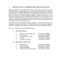
INTRODUCTION TO THE SIMRAD RD68 FIXED DSC VHF RADIO
The Simrad RD68 is a combined VHF radio, watch-keeping receiver and Class
D Digital Selective Calling (DSC) unit to facilitate routine and distress calling on
VHF Channel 70. Digitally Selected Calls are quicker and simpler to make than
traditional voice calls using Channel 16 and should a distress situation occur, an
alert can quickly be raised indicating identity, position and nature of the
emergency and automatically establish communication on the emergency voice
channel. The RD68 is robustly constructed using a pressure die cast aluminium
case for effective heat dissipation ensuring maximum transmission performance
even after many hours of constant use.
The RD68 has full international channel capability; 16 pre-programmed private
channels; features Dual Watch, Tri Watch, Scan and full memory operation;
back-lit LCD display and is available with either fist-mic or telephone handset.
The main components of the Simrad RD68 are:
1.1
Electronics PCBs
a.
b.
c.
d.
e.
1.2
Receiver / Transmitter PCB
Control PCB
Second Receiver PCB
Fist Mic
Telephone Handset
Drawing No. E03866
Drawing No. E03656
Drawing No. E03211
Drawing No. E03283
Drawing No. E03308
Mechanical Components
a.
b.
c.
d.
RD68 Chassis
RD68 Assembly
Fist Mic Assembly
Telephone Handset Assembly
Drawing No. E03848
Drawing No. E03847
Drawing No. E03161
Drawing No. E03162
3
SIMRAD
A KONGSBERG Company
SIMRAD Fixed VHF
DSC Radio
RD68
Operation
2
OPERATING THE SIMRAD DSC VHF RADIO
This Service Manual only contains operating instructions for those features of
the Simrad RD68 Radio that are not normally available to the end user. For
details of normal operation please refer to the Simrad RD68 Instruction Manual,
E03912.
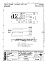
LCD Test Mode. The LCD test mode may be entered by holding Soft Keys 2
and 4 on power up. Depressing each key in turn will then fill the display with the
appropriate characters. The radio must be turned off to exit test mode.
4
SIMRAD
A KONGSBERG Company
SIMRAD Fixed VHF
DSC Radio
RD68
Assembly
Instructions
3
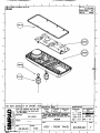
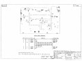
ASSEMBLY INSTRUCTIONS
3.1
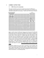
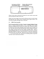
RD68 Chassis Pre-Assembly
The main transmitter and receiver and second receiver PCBs are a
matched pair and replacement of either requires the tuning of both to be
checked and adjusted as necessary. Position the PCB over the Chassis.
Apply a small amount of Hellerman sleeving oil to the part of the Red and
Black power and the red and blue NMEA leads inside the chassis, to
provide lubrication and facilitate withdrawal from the chassis as the board
is set down. Ensure that the 2 copper tags from the washer on the
Antenna socket are standing up clear and insert the tinned copper wire
from the rear of the Antenna socket up through the plated hole in the
board. Fit the PCB into the chassis, carefully pulling the 4 leads through
the grommet to remove excess from the chassis interior. Locate the PCB
over the ribs in the chassis and push down to position the PCB flat into
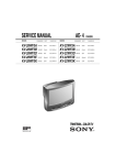
the casting. When the board is correctly fitted, refer to drawing No
E03848 and fit 2 - M3 X 10 screws 200048 into the front of the chassis to
secure the heatsink in place, do not fully tighten these screws at this
stage .
Fit 1 washer 200081 onto each of the 2 screws M3 x 16mm 200200, and
fit into the 2 holes at the back of the chassis. When all 4 screws are in
place, lightly press down on the front part of the PCB until the front panel
connectors are clearly visible and permit engagement of the front panel
without interference. (See drawing below)
5
When this has been achieved fully tighten the rear module screws and
then the heatsink screws at the front.
Solder the tinned copper wire from the Antenna socket into the board,
then fold down the 2 tags, from the Antenna socket copper washer, onto
the PCB and solder both tags down to the pads.
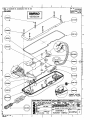
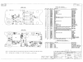
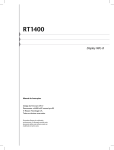
3.2
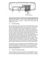
RD68 Final Assembly
Fit the Cover Seal E03117 into the top cover ensuring that the seal lays
into the recess around the cover. Refer to drawing E03847, place
Screen / Insulator Assembly E03223 on top of the PCB in the Chassis
Assembly E03848 with the Leatheriod insulator down towards the board.
Fit Top Cover onto Chassis assembly and fix down using 5 off M3 x 16
Pan Head Slot Screws fitted with M3 Nyltite Sealing Washers 200252,
fully tighten ensuring that the seal remains correctly fitted. Refer to
drawing E03849 and fit the Front Panel Seal E03116 to the Front Panel
Assembly E03850 as shown, ensuring that the 6 small 'feet' attached to
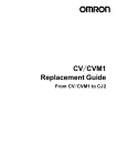
the seal sit down onto the PCB. Take the four sets of wires from PLUGS
1 – 4 on the front panel and, referring to the drawing below, plug them
into their correct connectors as shown.
6
Offer up the front panel to the chassis and, ensuring that the seal is still
correctly located, fit the front panel. Refer to drawing No.E03847 and
onto each of the four No.6 x 1/2" Pan Head Screws 200005, fit a M3.5
Nyltite Washer 200253. From the rear, fit these screws through the
chassis and into the front panel.
Screw on the front panel, fully
tightening the screws.
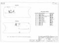
3.3
Fist Mic Assembly
Refer to Drawing No. E03161 and fit the PTT Grommet E03143 into the
web in the front case ensuring that it is correctly seated. From the end of
the Cable Assembly E03175 strip and remove the outer insulation for
15mm. Cut off the Blue ,Green, Orange and Black wires, (not used),
flush with the end of the outer insulation. Strip 5mm of insulation from
the ends of the Red and White wires, twist and sleeve the screen and tin
the ends. Pass the end of the cable up through the bottom hole in the
front case, apply a small quantity of Hellerman Sleeving Oil to the cable
and slide on Cable Grommet E03141. Pull the cable and grommet
through together, until the grommet is fully home, ensuring that the flat on
the head of the grommet lays against the inside of the case, then pull
cable back through grommet by approximately 100mm. Wipe off any
excess sleeving oil from the cable. Solder the cable connections to the
PCB and position the PCB assembly onto the 2 mounting pillars. Route
the cable into the case, pulling out any excess wire, until the PCB and
cable lay neatly into the case. Ensure the PTT Key hits the push switch
before fixing the PCB assemble into the case using 2 screws (200036).
Into the groove around the outside of the Rear Case E03133 fit a Case
Seal E03136 ensuring it is pushed fully home. Fit the PTT Key E03134
so that the spring leg in the centre of the key with a guide either side,
faces out, and the peg on the other side of the key faces into the case
front. Fit the rear case onto the front using washer (200257) and screw
(200023) and tighten firmly.
3.4
Telephone Handset Assembly
Refer to Drawing No. E03162 and fit the PTT Grommet E03143 into the
side wall of the front case ensuring that it is correctly seated. From the
end of the Cable Assembly E03175 strip and remove the outer insulation
7
for 35mm. Cut off the Blue wire flush with the outer insulation, (not
used). Cut back the Red wire to 20 mm long from the end of the outer
insulation, the Orange and Black wire to 30 mm and the Green and White
wire to 35 mm. Strip and tin the ends. Pass the end of the cable up
through the hole in the bottom of the front case, apply a small quantity of
Hellerman Sleeving Oil to the cable and slide on Cable Grommet
E03141. Pull the cable and grommet through together, until the grommet
is fully home into the case, ensuring that the flat on the head of the
grommet is facing out, not towards the wall of the case. Then pull cable
back through grommet by approximately 30mm. Wipe off any excess
sleeving oil from the cable. Secure with Cable Tie 200026. Fit the
handset weight E03311 and hold in place by fitting 3 Grommets 190024
onto the pillars. Solder the five wires and screen from the coiled cable
and the two wires from the speaker to the PCB E03309. Position the
PCB into the case on top of the three pillars retaining the weight and
using 3 Screws 200082, fix the PCB into the case. Fully tighten the 3
screws. Fit PTT Key and check that the key operates the switch. Into
the groove around the outside of the Rear Case E03140 fit Case Seal
E03142 ensuring it is pushed fully home. Fit the rear case onto the front,
ensuring the seal remains in place, using 6 Screws 200055 with washers
and tighten screws firmly to secure front and rear case halves together.
8
SIMRAD
A KONGSBERG Company
SIMRAD Fixed VHF
DSC Radio
RD68
Mechanical
Assembly
Drawings
4
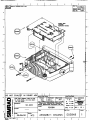
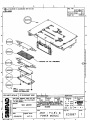
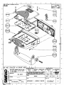
MECHANICAL ASSEMBLY DRAWINGS
4.1
4.2
4.3
4.4
4.5
4.6
Assembly Chassis
Assembly PCBs & Power Module
Assembly Mobile Radio
Assembly Front Panel
Assembly Fist Mic
Assembly Telephone Handset
E03848
E03867
E03847
E03849
E03557
E03558
9
SIMRAD
A KONGSBERG Company
SIMRAD Fixed VHF
DSC Radio
RD68
Circuit
Descriptions
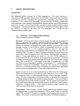
5
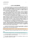
CIRCUIT DESCRIPTIONS
Introduction
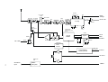
The SIMRAD RD68 consists of 3 PCB assemblies. The main Receiver /
Transmitter PCB assembly, Navico Part No. E03866, contains all the transmitter
and receiver circuitry including the synthesiser, modulator and audio power
amplifiers. The control PCB assembly, Navico Part No. E03656, houses the
microcontroller, user controls and interfaces, display module and ATIS detection
and mute circuitry. A full Class D DSC controller is also incorporated through a
V.23 modem. The second receiver, Channel 70 watchdog receiver, Navico Part
No. E03211, is fitted to the main Tx / Rx assembly, the 2 PCBs are an
interdependent matched pair.
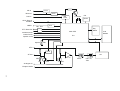
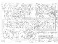
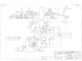
5.1
Receiver / Transmitter PCB Assembly
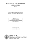
Refer to drawing number E02955.
Receiver. RF from the Antenna socket passes through the low pass PA
filter to a quarter wave match / switch L5, L6 and pin diode D1. During
transmissions, D1 is switched on to protect the receiver. There then
follows an optional attenuator and power splitter, to provide RF to the
second receiver in the RT1400, which is bypassed by link LK1 in the
RT1200. C214 is a 1nF coupling capacitor and L7, L8 and the
associated capacitors form a bandpass filter at the input to the RF preamplifier TR1. L9 and L11 form a further bandpass section before the
mixer TR2. The RF signal is fed to TR2 Source and the local oscillator to
Gate 1. Low side injection is used, i.e. the LO, TR105 buffered by
TR103 and TR104, is 21.4 MHz below the receive frequency. L13 forms
the drain load before matching through C25 and C26 to the 4 pole crystal
filter XTAL1 and XTAL2. The output of the filter is coupled by L14, C28
and C29 to the integrated IF amplifier / demodulator IC1. A second local
oscillator running at 21.855MHz produces the second IF of 455KHz.
XTAL4 is a 6 pole ceramic filter completing the necessary bandwidth
definition with quadrature coil L16 providing demodulation.
Audio from pin 9 of IC1 is de-emphasised by R20 and C43, buffered by
TR20 and distributed to the various audio stages on the control PCB.
The audio from pin 9 is also passed through a very high gain amplifier,
within IC1 and configured as a bandpass filter, to detector D2 to provide
a voltage proportional to the received signal strength. This level is fed to
the front panel to provide squelch control. The AF signal is returned from
the control panel after the volume and squelch controls to 2 audio power
amplifiers in bridge mode.
The internal speaker output remains live
when an external speaker is connected.
Transmitter. The LO switch / buffer TR102 switches the transmit signal
for amplification by controlled transistors TR101 and TR100 to drive the
hybrid PA module IC100 which is capable of generating the required 25
Watts. The output is switched through PIN diode D100 before passing
10
through the PA filter L1 to L4. L4 of this filter, with diodes D101 and
D102, forms a simple forward and reverse power detector to provide
power control and transmitter status indication on the front panel display.
The power control signal is fed to differential amplifier IC101 together
with the reference power signal from VR100 and VR101, to set the high
and low power levels. The output of this amplifier forms a regulated
supply with TR113 and TR114 to supply the PA drivers TR100 and
TR101. The reference input and supply for TR114 is fed from TR111
which is only turned on after the synthesiser is in lock.
Local Oscillator / Synthesizer. The main LO consists of TR105
connected as a Colpitts oscillator. Tuning is by L113, varactor VC102
and VC104. Band switching between receive and transmit is by PIN
diode D103. The output of the oscillator is buffered by a cascade pair
formed by TR104 and TR103 in receive and TR102 and TR104 in
transmit., the supply to TR102 and TR103 being switched between the 2
modes. The output is also buffered by TR118 to the input of the
synthesiser IC105. The reference frequency at 9.6 MHz is generated by
TR119 and controlled by XTAL101. C200, C115 and R157 form the
main loop filter with additional suppression of the reference frequency by
R179 and C204. The synthesiser is controlled from the control panel via
a 3 wire serial interface.
Modulator. Audio from the control panel is amplified by IC104b, the gain
being configured by R169, R173 and C169, to give the signal preemphasis. The output of the stage is peak detected by D3 and detector
TR1167 to provide a gain control signal to TR117 to enable limiting of
high level input signals. Temperature compensation of the limiter is
provided by thermistor TH1 and IC104a forms a high pass filter to meet
the 14dB / octave roll-off above 6kHz. The final output is fed to the
modulation diode VC101 via gain control VR102 which is set to a
maximum of 5kHz deviation.
Power Regulation and Switching. The 12 volt supply is switched on
the front panel and then feeds the audio amplifiers and regulators. The
RF power module takes power before the switch to minimise voltage
drops. D104 and D105 provide reverse polarity protection. A regulated
8v supply is provided by IC103 and 5v from IC107. The supplies for
receive and transmit circuits are switched by TR106 and TR110
controlled form the synthesiser via TR107 to TR109. IC105 controls the
switching of PIN diode D103 ensuring that there is a suitably high
reverse bias across it in the OFF condition.
NMEA Reception. (RD68 only) Position and time information, from a
GPS unit, is received in the form of NMEA data. This is opto-coupled into
the radio via R225, D5 and IC4. The data is then routed through to the
control PCB via PLG3.
11
XTAL4
L10, C214,
C215
D101,102
D1,D100
D2
Noise
Voltage
To 2nd Rx
TR2
TR1
21.4MHz
Rx AF Out
IF Chip
TR120
XTAL1 ,2
IC1
IC101,
TR113,114
XTAL3
TR102-105,
VC101,102, 104
D103
IC105
VCO &
Buffers
VR100
1W / 25W
TR112
IC100
TR100 TR101
Clock
Data
Enable 1
Synth
Osc
TR119
TR115,111
VR101
Lock
Detect
+
XTAL101
Pre-emphasis,
Limiting & HPF
IC104, D3,
TR116,117
Tx AF In
IC2
Rx AF In
R225, D5,
IC4
12
GPS Data
Input
NMEA
Reception
IC3
NMEA
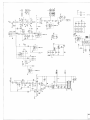
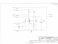
5.2
Control PCB Assembly.
Refer to drawing number E03656.
All the functions of the radio are controlled from this assembly by the
microprocessor IC4. The microprocessor has it own clock controlled by XTAL1
running at 7.15909MHz. Reset generator IC9 ensures that the microprocessor
starts up correctly and resets under low voltage conditions. The microprocessor
has a data bus interface driving the front panel display module. External
controls consist of a 21 push button key matrix, rotary squelch and volume
control VR1 and VR3 respectively. The level of illumination on the LCD and
keypad is controlled by TR7 driving LED’s 1 to 10 and the integral LED’s on the
LCD module.
Configuration data, MMSI and channel information is stored in the non volatile
memory IC5. This interfaces to IC4 via a 4 wire serial interface shared with the
synthesiser data to the Rx / Tx PCB assembly. Separate enables ensure that
the data is routed correctly.
Volume control VR3 controls the level of audio in the loudspeaker. Amplifier
IC2a boosts the level delivered to the handset earpiece. Individual mutes of the
handset and speaker audio are provided by TR3 and TR4 respectively, under
control of the microprocessor. The voltage on the squelch control and noise
input from the Rx/Tx PCB are read and the audio muted as appropriate.
Additionally the state of the handset is detected from SKT1 to mute the speaker
when the handset is off cradle (optional).
The handset interface is via connector SKT1. The microphone input is biased
for use with Electret microphones and may be muted by IC1a. The 12V output
is current limited by TR5 and TR6. The cradle and PTT lines are also used for
external data connections to a PC or third party accessories.
Data interfaces are provided for external programming via TR1 and TR2. NMEA
data is received from the Rx/Tx PCB via PLG2 and passed onto the
microprocessor, IC4, via IC1c.
Optional circuitry for ATIS detection consists of IC6, IC7, D1 and TR8.The
inclusion of IC7 allows the ATIS signal to be muted during reception. The
received audio is filtered by IC6c and IC6d which are followed by a zero
crossing detector formed by IC6a, IC6b, D1 and TR8. This signal is sent to a
second microprocessor, IC7, which measures the period of each half cycle of
the incoming signal. By counting the number of periods which might be an
ATIS signal the micro can decide whether ATIS is being received or not. When
this decision is made, after about 10ms, IC7 sets an output to inform IC4 to
mute the audio for 300ms. IC7 derives its clock and reset from the main
microprocessor IC4.
The ATIS and DSC signals are generated and decoded by the modem, IC8 and
surrounding components. TR9 switches the modulation index between that
required for DSC and ATIS. The output signal is then passed onto the
microphone audio via IC1b. Note that the microphone is muted by IC1a during
transmission of the ATIS or DSC signals.
13
The audio level required for alarms is controlled by IC1d. For normal key
‘beeps’the microprocessor, IC4, generates a square wave which is filtered and
reduced in level by R15, R75, C14 and C105 and then fed into the audio
amplifier via PLG1. For alarm generation IC1d short circuits R75 to increase the
level of signal being fed to the audio amplifier.
14
Mic in
IC1a
Mod out
IC1b
IC9
IC8
DSC in
7.15909MHz
FX604
Reset
Clock, Data &
Enables
NMEA
IC1c
TR1, TR2
Key
Matrix
PTT / Data Out
LCD
Module
Main CPU
Reverse Power
Carrier Power
Squelch Level
IC4
Squelch
VR1
AF In
IC1d
AF Out
IC7
IC2a
VR3
TR41
Analogue 0V
Earpiece Audio
TR3
IC6a,b
IC6c, D1,
TR8
15
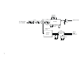
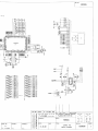
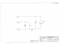
5.3
Second Receiver PCB Assembly
Refer to drawing number E03209.
The second receiver is connected to the main receiver at the power splitter L10, C215,
C214 and R205. The basic circuitry is the same as the receiver section of the main
receiver. L300, L301 and associated capacitors form the input bandpass section, prior to
the RF amplifier TR300. A second bandpass section is formed by L302 and L303, which
couple into the mixer at the source of TR301. Low side injection from the local oscillator is
fed into the gate. The output at 17.9MHz passes through the crystal filter XTAL300 and
XTAL301 to the second IF stage, IC300. Demodulated audio is buffered by IC302a.
TR304 and XTAL304 form the reference oscillator for the synthesiser, IC301. Data from
the front panel is fed from Clock, Data and Enable 2. C350, C355 and R345 form the
basic loop filter to control the frequency of the local oscillator, TR303, by varactor VC301.
The output of the local oscillator is buffered by TR302 before being coupled to the mixer
through band bass filter L307 and L308.
16
XTAL303
TR300
TR301
17.9MHz
DSC AF Out
IF Chip
RF from main
Rx-Tx Board
IC302
XTAL 300,
301
IC300
XTAL302
TR302, 302,
VC301
IC301
VCO &
Buffer
Clock
Data
Enable 2
Synth
Osc
XTAL304
TR305
17
SIMRAD
A KONGSBERG Company
SIMRAD Fixed VHF
DSC Radio
RD68
Circuit
Diagrams
6
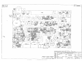
CIRCUIT DIAGRAMS
6.1
Circuit Schematics
Receiver / Transmitter Circuit Diagram
Control PCB Circuit Diagram
Second Receiver Circuit Diagram
Fist Mic Circuit Diagram
Telephone Handset Circuit Diagram
E02955
E03656
E03209
E03283
E03308
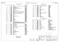
18
Component Lists and Layouts
Receiver / Transmitter PCB Front Assembly Detail
Receiver / Transmitter PCB Assembly Detail
Receiver / Transmitter PCB Rear Assembly Detail
Front Panel Assembly Detail (Sht 1)
ATIS Front Panel Assembly Detail
Second Receiver PCB Assembly Detail
Fist Mic PCB Assembly Detail
Telephone Handset PCB Assembly Detail
E03866(Sht 1)
E03866(Sht 2)
E03866(Sht 3)
E03658
E03865
E03211
E03285
E03309
19
SIMRAD
A KONGSBERG Company
SIMRAD Fixed VHF
DSC Radio
RD68
Programming and
Configuration
7
PROGRAMMING AND CONFIGURATION
Introduction
All Transmitting / Receiving characteristics of the RD68 Series radiotelephones
are stored in Non Volatile Memory (NVM). The NVM of any RD68 Series radio
can be programmed with new characteristics using the programming kit, Part
Number PR68.
The following features are available:
COUNTRY
Selects primary mode. NVMs with INT
(International) selected for the FIRST
COUNTRY flag will receive on the INT Rx
frequencies. The radio can be switched to
USA with weather channels if the
BACKLIGHT key is depressed on power up
unless the SELECTED MODE ONLY flag is
set.
(SECOND MODE – YES).
SECOND MODE
Enables or disables switch to USA with
weather channels.
SCANNING
Enables or disables SCAN and MEMORY
SCAN functions.
CHANNEL 10 SCAN
Enables or disables Channel 10 from SCAN
function.
DUAL WATCH
Enables or disables DUAL WATCH function.
TRI WATCH
Enables or disables TRI WATCH function.
ALTERNATE SCAN
Enables or disables ALTERNATE SCAN
function. Switches to Channel 16 between
each channel when scanning. For use in
Scandinavia only.
(1 – 16, 2 – 16, 3 – 16, 4 – 16).
FIRST KEY BEEP
Enables or disables confirmation key beep
from all first level functions. (NB. Second
level key beep cannot be disabled).
STARTUP CHANNEL
Selects channel to be displayed on power
up, usually Channel 16.
WATCH CHANNEL
Selects alternate channel to be monitored
when DUAL WATCH selected.
USA / CANADA
WEATHER CHANNELS
Enables or disables USA weather
channels.
20
DSC IDENTIFIER (MMSI) Stores Maritime Mobile Service Identity
(MMSI) number.
ATIS IDENTIFIER
Stores Automatic Transmission Identification
System (ATIS) Number.
INITIAL SET UP
The PR68 programming kit operates in conjunction with an IBM compatible PC.
The programme should be copied to the 'C’ drive on the PC hard disc into a
directory entitled RD68DATA
If using a monochrome monitor type MODE BW80. Connection between the
radio and PC is by means of the programming lead supplied with the kit from
the radio Mic Socket, on the front of the radio, to a 9 pin serial port on the PC.
Enter the programming set up software by typing “Prog68”. Place the radio into
programming mode by holding Soft Keys 1 and 3 and the LIGHTS Key whilst
powering up. Programming is entirely menu driven and self-explanatory.
RD68 RADIO CONFIGURATION PROGRAM
--------------------------------------------------------Version 1.1
Copyright (C) Simrad-Navico Ltd 2000
This program allows the dealer to configure the RD68 series
radios to any mode including the programming of private channels.
WARNING
-------------Incorrect use of this program could enable the radios to be used
in contravention of local regulations.
Which COM port is to be used? (1 or 2)
Type 1, 2 or [ESC] to exit program
21
RD68 RADIO CONFIGURATION PROGRAM
--------------------------------------------------------Using COM1 port on computer
NVM Data: NOT LOADED
Select option:1 - Load NVM data from Radio (Copy data from radio to PC)
2 - Load NVM data from File
(Load data from programme file)
3 - View/Modify NVM data
(View/change displayed data)
4 - Save NVM data to Radio
(Save displayed data to radio)
5 - Save NVM data to File
(Save data to new PC file)
6 - CLONE from existing Radio (Copy existing data from radio to radio)
7 - Exit Program
(Exit programme)
Use ↑↓ [Enter] or type option number, type [ESC] to exit program
Load NVM data from Radio
Connect Radio, press any key when ready
00:
01:
02:
03:
04:
05:
06:
07:
08:
09:
0A:
0B:
0C:
0D:
0E:
OF:
10:
11:
12:
13:
14:
15:
16:
17:
18:
19:
1A:
1B:
1C:
1D:
1E:
1F:
20:
21:
22:
23:
24:
25:
26:
27:
28:
29:
2A:
2B:
2C:
2D:
2E:
2F:
30:
31:
32:
33:
34:
35:
36:
37:
38:
39:
3A:
3B:
3C:
3D:
3E:
3F:
NVM data
40:
41:
42:
43:
44:
45:
46:
47:
48:
49:
4A:
4B:
4C:
4D:
4E:
4F:
50:
51:
52:
53:
54:
55:
56:
57:
58:
59:
5A:
5B:
5C:
5D:
5E:
5F:
60:
61:
62:
63:
64:
65:
66:
67:
68:
69:
6A:
6B:
6C:
6D:
6E:
6F:
70:
71:
72:
73:
74:
75:
76:
77:
78:
79:
7A:
7B:
7C:
7D:
7E:
7F:
Any key to continue, [ESC] to exit
22
Load NVM data from Radio
Connect Radio, press any key when ready
Failed – check connections, is radio turned on?
00:
01:
02:
03:
04:
05:
06:
07:
08:
09:
0A:
0B:
0C:
0D:
0E:
OF:
10:
11:
12:
13:
14:
15:
16:
17:
18:
19:
1A:
1B:
1C:
1D:
1E:
1F:
20:
21:
22:
23:
24:
25:
26:
27:
28:
29:
2A:
2B:
2C:
2D:
2E:
2F:
30:
31:
32:
33:
34:
35:
36:
37:
38:
39:
3A:
3B:
3C:
3D:
3E:
3F:
NVM data
40:
41:
42:
43:
44:
45:
46:
47:
48:
49:
4A:
4B:
4C:
4D:
4E:
4F:
50:
51:
52:
53:
54:
55:
56:
57:
58:
59:
5A:
5B:
5C:
5D:
5E:
5F:
60:
61:
62:
63:
64:
65:
66:
67:
68:
69:
6A:
6B:
6C:
6D:
6E:
6F:
70:
71:
72:
73:
74:
75:
76:
77:
78:
79:
7A:
7B:
7C:
7D:
7E:
7F:
Any key to continue, [ESC] to exit
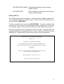
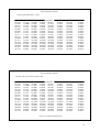
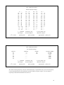
Load NVM data from Radio
Connect Radio, press any key when ready
NVM data loaded successfully.
00:1068
01:3200
02:B111
03:1101
04:0000
05:0004
06:0411
07:1111
08:1111
09:1BB3
0A:1111
0B:1110
0C:0030
0D:0004
0E:4011
OF:1111
10:1110
11:0BBB
12:3333
13:3333
14:3300
15:3333
16:3333
17:3333
18:33FF
19:5431
1A:7232
1B:0000
1C:0000
1D:0000
1E:0000
1F:0000
20:0000
21:0000
22:0000
23:0000
24:0000
25:0000
26:0000
27:0000
28:0000
29:DFD2
2A:FFFF
2B:FFFF
2C:0000
2D:0000
2E:0000
2F:0000
NVM data
30:0000
40:9876
31:0000
41:5432
32:0000
42:10FF
33:0000
43:FFFF
34:0000
44:FFFF
35:0000
45:1919
36:0000
46:0606
37:0000
47:1010
38:1016
48:FFFF
39:0010
49:FFFF
3A:FFFF 4A:FFFF
3B:FFFF 4B:FFFF
3C:FFFF 4C:FFFF
3D:FFFF 4D:FFFF
3E:FFFF 4E:FFFF
3F:0439
4F:FFFF
50:FFFF
51:FFFF
52:FFFF
53:FFFF
54:FFFF
55:FFFF
56:FFFF
57:FFFF
58:FFFF
59:FFFF
5A:FFFF
5B:FFFF
5C:FFFF
5D:FFFF
5E:FFFF
5F:FFFF
60:FFFF
61:FFFF
62:FFFF
63:FFFF
64:FFFF
65:FFFF
66:FFFF
67:FFFF
68:FFFF
69:FFFF
6A:FFFF
6B:FFFF
6C:FFFF
6D:FFFF
6E:FFFF
6F:FFFF
70:FFFF
71:FFFF
72:FFFF
73:FFFF
74:FFFF
75:FFFF
76:FFFF
77:FFFF
78:FFFF
79:FFFF
7A:FFFF
7B:FFFF
7C:FFFF
7D:FFFF
7E:FFFF
7F:FF83
Any key to continue, [ESC] to exit
23
RD68 RADIO CONFIGURATION PROGRAM
--------------------------------------------------------Using COM1 port on computer
NVM Data: LOADED
Software: 0.4
Select option:1 - Load NVM data from Radio
2 - Load NVM data from File
3 - View/Modify NVM data
4 - Save NVM data to Radio
5 - Save NVM data to File
6 - CLONE from existing Radio
7 – Exit Program
Use ↑↓ [Enter] or type option number, type [ESC] to exit program
Load NVM data from File
Enter NVM Data File Name:
00:
01:
02:
03:
04:
05:
06:
07:
08:
09:
0A:
0B:
0C:
0D:
0E:
OF:
10:
11:
12:
13:
14:
15:
16:
17:
18:
19:
1A:
1B:
1C:
1D:
1E:
1F:
20:
21:
22:
23:
24:
25:
26:
27:
28:
29:
2A:
2B:
2C:
2D:
2E:
2F:
30:
31:
32:
33:
34:
35:
36:
37:
38:
39:
3A:
3B:
3C:
3D:
3E:
3F:
NVM data
40:
41:
42:
43:
44:
45:
46:
47:
48:
49:
4A:
4B:
4C:
4D:
4E:
4F:
50:
51:
52:
53:
54:
55:
56:
57:
58:
59:
5A:
5B:
5C:
5D:
5E:
5F:
60:
61:
62:
63:
64:
65:
66:
67:
68:
69:
6A:
6B:
6C:
6D:
6E:
6F:
70:
71:
72:
73:
74:
75:
76:
77:
78:
79:
7A:
7B:
7C:
7D:
7E:
7F:
Enter file name {and path if required) or [ESC] to exit
24
Load NVM data from File
Enter NVM Data File Name:
File cannot be found or cannot be opened
00:
01:
02:
03:
04:
05:
06:
07:
08:
09:
0A:
0B:
0C:
0D:
0E:
OF:
10:
11:
12:
13:
14:
15:
16:
17:
18:
19:
1A:
1B:
1C:
1D:
1E:
1F:
20:
21:
22:
23:
24:
25:
26:
27:
28:
29:
2A:
2B:
2C:
2D:
2E:
2F:
30:
31:
32:
33:
34:
35:
36:
37:
38:
39:
3A:
3B:
3C:
3D:
3E:
3F:
NVM data
40:
41:
42:
43:
44:
45:
46:
47:
48:
49:
4A:
4B:
4C:
4D:
4E:
4F:
50:
51:
52:
53:
54:
55:
56:
57:
58:
59:
5A:
5B:
5C:
5D:
5E:
5F:
60:
61:
62:
63:
64:
65:
66:
67:
68:
69:
6A:
6B:
6C:
6D:
6E:
6F:
70:
71:
72:
73:
74:
75:
76:
77:
78:
79:
7A:
7B:
7C:
7D:
7E:
7F:
Enter file name {and path if required) or [ESC] to exit
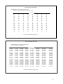
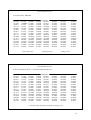
Load NVM data from Radio
Enter NVM Data File Name: RD68DATA/B1.DAT
File loaded successfully.
00:1068
01:3200
02:B111
03:1101
04:0000
05:0004
06:0411
07:1111
08:1111
09:1BB3
0A:1111
0B:1110
0C:0030
0D:0004
0E:4011
OF:1111
10:1110
11:0BBB
12:3333
13:3333
14:3300
15:3333
16:3333
17:3333
18:33FF
19:5431
1A:7232
1B:0000
1C:0000
1D:0000
1E:0000
1F:0000
20:0000
21:0000
22:0000
23:0000
24:0000
25:0000
26:0000
27:0000
28:0000
29:DFD2
2A:FFFF
2B:FFFF
2C:0000
2D:0000
2E:0000
2F:0000
NVM data
30:0000
40:9876
31:0000
41:5432
32:0000
42:10FF
33:0000
43:FFFF
34:0000
44:FFFF
35:0000
45:1919
36:0000
46:0606
37:0000
47:1010
38:1016
48:FFFF
39:0010
49:FFFF
3A:FFFF 4A:FFFF
3B:FFFF 4B:FFFF
3C:FFFF 4C:FFFF
3D:FFFF 4D:FFFF
3E:FFFF 4E:FFFF
3F:0439
4F:FFFF
50:FFFF
51:FFFF
52:FFFF
53:FFFF
54:FFFF
55:FFFF
56:FFFF
57:FFFF
58:FFFF
59:FFFF
5A:FFFF
5B:FFFF
5C:FFFF
5D:FFFF
5E:FFFF
5F:FFFF
60:FFFF
61:FFFF
62:FFFF
63:FFFF
64:FFFF
65:FFFF
66:FFFF
67:FFFF
68:FFFF
69:FFFF
6A:FFFF
6B:FFFF
6C:FFFF
6D:FFFF
6E:FFFF
6F:FFFF
70:FFFF
71:FFFF
72:FFFF
73:FFFF
74:FFFF
75:FFFF
76:FFFF
77:FFFF
78:FFFF
79:FFFF
7A:FFFF
7B:FFFF
7C:FFFF
7D:FFFF
7E:FFFF
7F:FF83
Any key to continue
25
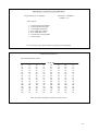
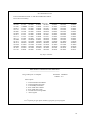
View/Modify NVM data
Configuration Settings
Country:
Second Mode Enabled:
Scanning Enabled:
Channel 10 Scan Enabled:
Dual Watch Enabled:
Tri Watch Enabled:
Alternate Scan Enabled:
User can disable first key beep:
Startup Channel (SC):
Watch Channel (WC):
USA/Canada Weather Channels:
DSC Identifier (MMSI):
INT
NO
YES
YES
YES
YES
NO
YES
16
16
NO
----------
← ↑↓→ select
[Pg Dn] done
[Enter] modify
[ESC] exit
OR if radio is ATIS capable
View/Modify NVM data
Configuration Settings
Country:
Second Mode Enabled:
Scanning Enabled:
Channel 10 Scan Enabled:
Dual Watch Enabled:
Tri Watch Enabled:
Alternate Scan Enabled:
User can disable first key beep:
Startup Channel (SC):
Watch Channel (WC):
USA/Canada Weather Channels:
DSC Identifier (MMSI):
INT
NO
YES
YES
YES
YES
NO
YES
16
16
NO
----------
← ↑↓→ select
[Pg Dn] done
[Enter] modify
[ESC] exit
26
Save NVM data to Radio
Clear Log and Directory? {Y/N}
00:1068
01:3200
02:B111
03:1101
04:0000
05:0004
06:0411
07:1111
08:1111
09:1BB3
0A:1111
0B:1110
0C:0030
0D:0004
0E:4011
OF:1111
10:1110
11:0BBB
12:3333
13:3333
14:3300
15:3333
16:3333
17:3333
18:33FF
19:5431
1A:7232
1B:0000
1C:0000
1D:0000
1E:0000
1F:0000
20:0000
21:0000
22:0000
23:0000
24:0000
25:0000
26:0000
27:0000
28:0000
29:DFD2
2A:FFFF
2B:FFFF
2C:0000
2D:0000
2E:0000
2F:0000
NVM data
30:0000
40:9876
31:0000
41:5432
32:0000
42:10FF
33:0000
43:FFFF
34:0000
44:FFFF
35:0000
45:1919
36:0000
46:0606
37:0000
47:1010
38:1016
48:FFFF
39:0010
49:FFFF
3A:FFFF 4A:FFFF
3B:FFFF 4B:FFFF
3C:FFFF 4C:FFFF
3D:FFFF 4D:FFFF
3E:FFFF 4E:FFFF
3F:0439
4F:FFFF
50:FFFF
51:FFFF
52:FFFF
53:FFFF
54:FFFF
55:FFFF
56:FFFF
57:FFFF
58:FFFF
59:FFFF
5A:FFFF
5B:FFFF
5C:FFFF
5D:FFFF
5E:FFFF
5F:FFFF
60:FFFF
61:FFFF
62:FFFF
63:FFFF
64:FFFF
65:FFFF
66:FFFF
67:FFFF
68:FFFF
69:FFFF
6A:FFFF
6B:FFFF
6C:FFFF
6D:FFFF
6E:FFFF
6F:FFFF
70:FFFF
71:FFFF
72:FFFF
73:FFFF
74:FFFF
75:FFFF
76:FFFF
77:FFFF
78:FFFF
79:FFFF
7A:FFFF
7B:FFFF
7C:FFFF
7D:FFFF
7E:FFFF
7F:FF83
60:FFFF
61:FFFF
62:FFFF
63:FFFF
64:FFFF
65:FFFF
66:FFFF
67:FFFF
68:FFFF
69:FFFF
6A:FFFF
6B:FFFF
6C:FFFF
6D:FFFF
6E:FFFF
6F:FFFF
70:FFFF
71:FFFF
72:FFFF
73:FFFF
74:FFFF
75:FFFF
76:FFFF
77:FFFF
78:FFFF
79:FFFF
7A:FFFF
7B:FFFF
7C:FFFF
7D:FFFF
7E:FFFF
7F:FF83
Save NVM data to Radio
Connect radio, press any key when ready
00:1068
01:3200
02:B111
03:1101
04:0000
05:0004
06:0411
07:1111
08:1111
09:1BB3
0A:1111
0B:1110
0C:0030
0D:0004
0E:4011
OF:1111
10:1110
11:0BBB
12:3333
13:3333
14:3300
15:3333
16:3333
17:3333
18:33FF
19:5431
1A:7232
1B:0000
1C:0000
1D:0000
1E:0000
1F:0000
20:0000
21:0000
22:0000
23:0000
24:0000
25:0000
26:0000
27:0000
28:0000
29:DFD2
2A:FFFF
2B:FFFF
2C:0000
2D:0000
2E:0000
2F:0000
NVM data
30:0000
40:9876
31:0000
41:5432
32:0000
42:10FF
33:0000
43:FFFF
34:0000
44:FFFF
35:0000
45:1919
36:0000
46:0606
37:0000
47:1010
38:1016
48:FFFF
39:0010
49:FFFF
3A:FFFF 4A:FFFF
3B:FFFF 4B:FFFF
3C:FFFF 4C:FFFF
3D:FFFF 4D:FFFF
3E:FFFF 4E:FFFF
3F:0439
4F:FFFF
50:FFFF
51:FFFF
52:FFFF
53:FFFF
54:FFFF
55:FFFF
56:FFFF
57:FFFF
58:FFFF
59:FFFF
5A:FFFF
5B:FFFF
5C:FFFF
5D:FFFF
5E:FFFF
5F:FFFF
Any key to continue, [ESC] to exit
27
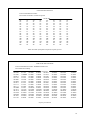
Save NVM data to File
Enter Data Ident: BRITISH
00:1068
01:3200
02:B111
03:1101
04:0000
05:0004
06:0411
07:1111
08:1111
09:1BB3
0A:1111
0B:1110
0C:0030
0D:0004
0E:4011
OF:1111
10:1110
11:0BBB
12:3333
13:3333
14:3300
15:3333
16:3333
17:3333
18:33FF
19:5431
1A:7232
1B:0000
1C:0000
1D:0000
1E:0000
1F:0000
20:0000
21:0000
22:0000
23:0000
24:0000
25:0000
26:0000
27:0000
28:0000
29:DFD2
2A:FFFF
2B:FFFF
2C:0000
2D:0000
2E:0000
2F:0000
NVM data
30:0000
40:9876
31:0000
41:5432
32:0000
42:10FF
33:0000
43:FFFF
34:0000
44:FFFF
35:0000
45:1919
36:0000
46:0606
37:0000
47:1010
38:1016
48:FFFF
39:0010
49:FFFF
3A:FFFF 4A:FFFF
3B:FFFF 4B:FFFF
3C:FFFF 4C:FFFF
3D:FFFF 4D:FFFF
3E:FFFF 4E:FFFF
3F:0439
4F:FFFF
Enter Ident Text
50:FFFF
51:FFFF
52:FFFF
53:FFFF
54:FFFF
55:FFFF
56:FFFF
57:FFFF
58:FFFF
59:FFFF
5A:FFFF
5B:FFFF
5C:FFFF
5D:FFFF
5E:FFFF
5F:FFFF
[Enter] for none
60:FFFF
61:FFFF
62:FFFF
63:FFFF
64:FFFF
65:FFFF
66:FFFF
67:FFFF
68:FFFF
69:FFFF
6A:FFFF
6B:FFFF
6C:FFFF
6D:FFFF
6E:FFFF
6F:FFFF
70:FFFF
71:FFFF
72:FFFF
73:FFFF
74:FFFF
75:FFFF
76:FFFF
77:FFFF
78:FFFF
79:FFFF
7A:FFFF
7B:FFFF
7C:FFFF
7D:FFFF
7E:FFFF
7F:FF83
[ESC] to exit
Save NVM data to File
Enter NVM Data Filename: C:\MY DOCUMENTS\UK.DAT
00:1068
01:3200
02:B111
03:1101
04:0000
05:0004
06:0411
07:1111
08:1111
09:1BB3
0A:1111
0B:1110
0C:0030
0D:0004
0E:4011
OF:1111
10:1110
11:0BBB
12:3333
13:3333
14:3300
15:3333
16:3333
17:3333
18:33FF
19:5431
1A:7232
1B:0000
1C:0000
1D:0000
1E:0000
1F:0000
20:0000
21:0000
22:0000
23:0000
24:0000
25:0000
26:0000
27:0000
28:0000
29:DFD2
2A:FFFF
2B:FFFF
2C:0000
2D:0000
2E:0000
2F:0000
30:0000
31:0000
32:0000
33:0000
34:0000
35:0000
36:0000
37:0000
38:1016
39:0010
3A:FFFF
3B:FFFF
3C:FFFF
3D:FFFF
3E:FFFF
3F:0439
BRITISH
40:9876
41:5432
42:10FF
43:FFFF
44:FFFF
45:1919
46:0606
47:1010
48:FFFF
49:FFFF
4A:FFFF
4B:FFFF
4C:FFFF
4D:FFFF
4E:FFFF
4F:FFFF
50:FFFF
51:FFFF
52:FFFF
53:FFFF
54:FFFF
55:FFFF
56:FFFF
57:FFFF
58:FFFF
59:FFFF
5A:FFFF
5B:FFFF
5C:FFFF
5D:FFFF
5E:FFFF
5F:FFFF
60:FFFF
61:FFFF
62:FFFF
63:FFFF
64:FFFF
65:FFFF
66:FFFF
67:FFFF
68:FFFF
69:FFFF
6A:FFFF
6B:FFFF
6C:FFFF
6D:FFFF
6E:FFFF
6F:FFFF
70:FFFF
71:FFFF
72:FFFF
73:FFFF
74:FFFF
75:FFFF
76:FFFF
77:FFFF
78:FFFF
79:FFFF
7A:FFFF
7B:FFFF
7C:FFFF
7D:FFFF
7E:FFFF
7F:FF83
Enter file name (and path if required) or [ESC] to exit
28
Save NVM data to File
Enter NVM Data Filename: C:\MY DOCUMENTS\UK.DAT
File written successfully
00:1068
01:3200
02:B111
03:1101
04:0000
05:0004
06:0411
07:1111
08:1111
09:1BB3
0A:1111
0B:1110
0C:0030
0D:0004
0E:4011
OF:1111
10:1110
11:0BBB
12:3333
13:3333
14:3300
15:3333
16:3333
17:3333
18:33FF
19:5431
1A:7232
1B:0000
1C:0000
1D:0000
1E:0000
1F:0000
20:0000
21:0000
22:0000
23:0000
24:0000
25:0000
26:0000
27:0000
28:0000
29:DFD2
2A:FFFF
2B:FFFF
2C:0000
2D:0000
2E:0000
2F:0000
30:0000
31:0000
32:0000
33:0000
34:0000
35:0000
36:0000
37:0000
38:1016
39:0010
3A:FFFF
3B:FFFF
3C:FFFF
3D:FFFF
3E:FFFF
3F:0439
BRITISH
40:9876
41:5432
42:10FF
43:FFFF
44:FFFF
45:1919
46:0606
47:1010
48:FFFF
49:FFFF
4A:FFFF
4B:FFFF
4C:FFFF
4D:FFFF
4E:FFFF
4F:FFFF
50:FFFF
51:FFFF
52:FFFF
53:FFFF
54:FFFF
55:FFFF
56:FFFF
57:FFFF
58:FFFF
59:FFFF
5A:FFFF
5B:FFFF
5C:FFFF
5D:FFFF
5E:FFFF
5F:FFFF
60:FFFF
61:FFFF
62:FFFF
63:FFFF
64:FFFF
65:FFFF
66:FFFF
67:FFFF
68:FFFF
69:FFFF
6A:FFFF
6B:FFFF
6C:FFFF
6D:FFFF
6E:FFFF
6F:FFFF
70:FFFF
71:FFFF
72:FFFF
73:FFFF
74:FFFF
75:FFFF
76:FFFF
77:FFFF
78:FFFF
79:FFFF
7A:FFFF
7B:FFFF
7C:FFFF
7D:FFFF
7E:FFFF
7F:FF83
Any key to continue
RD68 RADIO CONFIGURATION PROGRAM
--------------------------------------------------------Using COM1 port on computer
NVM Data: LOADED
Software: 0.4
Select option:1 - Load NVM data from Radio
2 - Load NVM data from File
3 - View/Modify NVM data
4 - Save NVM data to Radio
5 - Save NVM data to File
6 - CLONE from existing Radio
7 – Exit Program
Use ↑↓ [Enter] or type option number, type [ESC] to exit program
29
View / Modify NVM data
Normal Channel Settings
0:--01 : - - D
02 : - - D
03 : - - D
04 : - - D
05 : - - D
06 : - - S
07 : - - D
08 : - - S
09 : - - D
10 : - - D
11 : - - D
12 : - - D
13 : - - D
14 : - - D
15 : - L S
16 : - - S
17 : - L S
18 : - - D
19 : - - D
20 : - - D
21 : - - D
22 : - - D
23 : - - D
24 : - - D
25 : - - D
26 : - - D
27 : - - D
28 : - - D
29 : - - 31 : - - 37 : - - -
(- - -) disabled
(S) Simplex
← ↑↓→ select
60 : - - D
61 : - - D
62 : - - D
63 : - - D
64 : - - D
65 : - - D
66 : - - D
67 : - - S
68 : - - S
69 : - - S
70 : - - 71 : - - S
72 : - - S
73 : - - S
74 : - - S
75 : - - -
(T) Receive only
(D) semi-Duplex
[Delete] clear
76 : - - 77 : - - S
78 : - - D
79 : - - D
80 : - - D
81 : - - D
82 : - - D
83 : - - D
84 : - - D
85 : - - D
86 : - - D
87 : - - D
88 : - - D
89 : - - 90 : - - 99 : - - -
(L) Low power only
(R) Reverse duplex
[Enter] modify
[Pg Dn] done
[ESC] exit
View / Modify NVM data
Aux Channel Settings
Channel
A1
A2
A3
A4
A5
A6
Attributes
--S
--S
--------(- - -) disabled
(S) Simplex
← ↑↓→ select
[Delete] clear
(T) Receive only
(D) semi-Duplex
[Enter] modify
Display
M
M2
Frequency (MHz)
157.850
161.425
0.000
0.000
0.000
0.000
(L) Low power only
(R) Reverse duplex
[Pg Dn] done
[ESC] exit
NB. When entering frequency, only the transmit frequency is requested for entry, the receive frequency
is entered automatically by the programme regardless whether simplex, duplex or reverse duplex is
required provided that the attributes have been set.
30
View / Modify NVM data
Private Channel Settings
Channel
Attributes
P0
P2
P3
P4
P5
P6
P7
P8
P9
-------------------
Frequency (MHz)
0.000
0.000
0.000
0.000
0.000
0.000
0.000
0.000
0.000
Password protection is OFF use [F4] key to change
(- - -) disabled
(S) Simplex
← ↑↓→ select
(T) Receive only
(D) semi-Duplex
[Delete] clear
[Enter] modify
(L) Low power only
(R) Reverse duplex
[Pg Dn] done
[ESC] exit
31
SIMRAD
A KONGSBERG Company
SIMRAD Fixed VHF
DSC Radio
RD68
Fault
Finding
8
FAULT FINDING
8.1
Common User Faults
None Yet Identified.
8.2
Common Technical Faults
None Yet Identified
32
SIMRAD
A KONGSBERG Company
SIMRAD Fixed VHF
DSC Radio
RD68
Spare
Parts
Detail
9
SPARE PARTS DETAIL
9.1
Spares Packs
Part No.
RTPK18
RTPK18:A
RTPK19
RTPK19:A
RTPK20
RTPK21
Description
Front Panel Assembly
Front Panel Assembly ATIS Version
Front Panel PCB
Front Panel PCB ATIS Version
Front Panel Assembly (Minus PCB)
PCBs & Power Module Assembly
Items common to RT1200, RT1400 and RD68
Part No.
RTPK9
MB1000:BK
RTPK12
RTPK13
RTPK15
THS4:SIM
CRDL1:BK
FTM5:SIM
9.2
Bottom Cover Kit
Standard Mounting Kit – Black
Power Module Kit
Chassis Assembly
Accessory Kit
Telephone Handset – Black
Handset Cradle – Black
Fist Mic Assembly – Black
Service Aids
Part No.
PR68
Description
Description
Programming Kit
33
SIMRAD
A KONGSBERG Company
SIMRAD Fixed VHF
DSC Radio
RD68
Technical
Notes
10
TECHNICAL NOTES
None Yet Issued
34