1
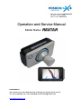
Document number: PN# 080320-00
Revision number: Rev01
Date of Issue: 2008-05-14
Operation and Service Manual
Model Name: REXTAR
PREPARED BY:
4Fl. Unitech ville, 1141-2, Baeksuk-dong, Ilsandong-gu, Goyang, Korea 411-722
Tel. +82-31-906-9007, Fax. +82-31-908-4208, E-mail. [email protected]
http://www.poskom.com
(This page intentionally left blank)
Operation and Service Manual
Model Name: REXTAR
(This page intentionally left blank)
Table of Contents
Part I. Operation Manual ............................................................................................. 1
1. Basic Instructions................................................................................................................ 1
2. Notes to the User ................................................................................................................ 4
3. Storage and Operating Conditions...................................................................................... 6
4. Caution: Radioactivity ......................................................................................................... 7
5. Parts and Components ....................................................................................................... 8
6. Specifications...................................................................................................................... 9
7. Name of Each Component ............................................................................................... 13
8. Operation .......................................................................................................................... 27
9. Operating Instructions....................................................................................................... 29
10. Instructions for Battery Use ............................................................................................ 37
11.Using the UMPC .............................................................................................................. 39
PART II. Service Manual ........................................................................................... 50
1. Notes to the User .............................................................................................................. 50
2. Regular Maintenance........................................................................................................ 51
3. Block Diagrams................................................................................................................. 52
4. Common Error Codes ....................................................................................................... 53
5. Circuit Diagrams ............................................................................................................... 54
(This page intentionally left blank)
POSKOM Co., Ltd.
P
Paarrtt II.. O
Oppeerraattiioonn M
Maannuuaall
1. Basic
1) Outline
REXTAR is one of the POSKOM battery-powered portable dental x-ray series. REXTAR is the
most compact and light-weighted, yet the most powerful High-Frequency X-ray device in the
portable devices market. All X-ray devices in the battery-powered portable devices series are
Ripple-free HF-type X-ray generating devices, which produce 40~50% more powerful output than
other portable X-ray devices on the market; moreover, its UMPC sets REXTAR apart from other
battery-powered portable series of its kind. UMPC can be used to construct of a DR System, as
well as for the ordinary UMPC functions.
REXTAR dental-use X-ray device is perfectly designed for medical diagnostic situations requiring
ease of use and portability.
2) Features
◈ Ultra-lightweight, ultra-compact dental-use X-ray generator
◈ High frequency X-ray generator
◈ High output at 70kV / 2mA
◈ UMPC with built-in touch screen monitor for user convenience
◈ X-ray function controlled by a single button for added convenience
◈ UMPC provides a USB-controlled restraint function against excessive X-ray radiation
◈ supporting stand topped a battery-charger
REXTAR Manual
PN# 080320-00
Rev.01
Page:1
POSKOM Co., Ltd.
3) Manual
This manual covers all aspects pertaining to product operation and services. The Services Manual
also offers information about the main points of installation, as well as on-site adjustment and
continuous maintenance of the device.
This manual may not take the place of education certified by a licensed department of medicine or
radiology. The following device may only be used by personnel trained in the operation and the
diagnostic use of X-ray devices.
Apart from its independent use, the following device may also be used with a portable support
device or, in conjunction with a device that may be loaded with an X-ray tube, with a table intended
for X-ray use, and a variety of similar types of diagnostic X-ray devices.
4) Attention
This manual is a guide pertaining to the safe use and operation of REXTAR portable X-ray device.
The user of said device must receive instruction and training in the use of X-ray devices, and may
only refer to this manual in the context of said instruction. The proprietor of REXTAR portable X-ray
device has an additional obligation to receive proper instruction from regional officials and ensure
that only qualified personnel may operate this device.
There may be latent hazards associated with the use of dental electric equipment and X-ray
devices latent hazards. All users and operators of this device must be fully aware of the safety and
emergency measures and operation instructions set forth in this booklet.
Each device manufactured by POSKOM Co. Ltd. is certified to comply with
safety and health concerns by including restraints on radioactivity in its
construction, according to United States federal law Article J, Section 1,
Paragraph 21 and according to European Union general provision
EN60601 for protection against radioactive rays generated from
diagnostic X-ray devices, under IEC601-1-3.
POSKOM Co. Ltd. does not accept liability for casualties or losses arising
from misuse or abuse of REXTAR portable X-ray device.
Additional questions concerning safety or miscellaneous matters should be referred to the
POSKOM Co. Ltd. Service Team, or to the regional retailer or distributor.
Page:2
PN# 080320-00
Rev.01
REXTAR Manual
POSKOM Co., Ltd.
5) Caution and Warning Signs
Latent hazards may arise through improper use of X-ray devices. Such hazards are noted by
warning notices as shown below concerning crucial safety and prevention measures.
※ Information ※
The Operation Manual details operation procedures for the safe and
efficient use of REXTAR product for X-ray technicians, radiation
technician, and other medical institutions using REXTAR X-ray device.
※CAUTION※
Failure to comply with the following safety provisions may
result in X-rays posing a danger to both the patient and the
operator of the device.
REXTAR Manual
PN# 080320-00
Rev.01
Page:3
POSKOM Co., Ltd.
2. Notes to the User
1) Machinery
※CAUTION※
This device has not been waterproofed.
The central concern in the design of REXTAR portable X-ray device is your safety and
convenience. However, to better ensure your safety when operating the device, we request your
adherence to the following regulations.
This device must be operated only under the supervision of a legally qualified individual.
REXTAR was designed to generate radioactive rays, and cannot be used for any other purpose,
including transparency.
REXTAR is to be used in diagnosis only, and cannot be used for treatment purposes.
REXTAR has been designated as a Class 1 Type B device, in conformance with provisions
IEC60601-1, 2.
REXTAR may not be altered or manipulated at the discretion of the individual. In the case that
such changes cannot be avoided, all inquiries must be directed to the POSKOM Co. Ltd.
Service Team, or to a retail center licensed for service.
REXTAR has been adjusted for the highest level of function. If a product should be discovered
defective, immediately turn off the device and report the incidence to the POSKOM Co.
Ltd. Service Team, or to a retail center licensed for service.
REXTAR can be used interchangeably or in conjunction with other devices. If you should desire to
link another company’s product with REXTAR, inquire with the POSKOM Co. Ltd. Service
Team, or to a retail center licensed for service.
Page:4
PN# 080320-00
Rev.01
REXTAR Manual
POSKOM Co., Ltd.
2) Batteries
※Caution※
Failure to properly dispose of used batteries may lead to
explosions or fire
Each country and region may have differing rules and regulations concerning the disposal of used
batteries. Disposal of batteries must follow these regional regulations.
Throwing, taking apart, or having external pressure applied to batteries increases the risk of bodily
harm, as well as of fire and explosion.
Using batteries not approved by POSKOM Co. Ltd. with this device increases the risk of fire and
explosion.
Batteries being stored separately must not come into contact with metal. Contact with a metal
object will provoke an excessive electrical current that will raise the temperature to such a degree
that there is risk of burns or of the battery being damaged.
.
Only battery chargers approved by POSKOM Co. Ltd. may be used. Other battery chargers pose a
risk of damage to both the battery and the device.
Heating batteries or putting them near flames poses a risk of injury, or of explosion and fire.
REXTAR Manual
PN# 080320-00
Rev.01
Page:5
POSKOM Co., Ltd.
3. Storage and Operating Conditions
1) Storage
For proper operation and maintenance, please avoid following places.
- Where the equipment is exposed to water vapor.
- Where the equipment is exposed to direct sunlight.
- Where the equipment is exposed to heavy dust.
- Where the equipment is exposed to high humidity.
- Where there is insufficient ventilation.
- Where the equipment is exposed to salty atmosphere.
- Where the equipment is exposed to chemicals or gas.
2) Operating Conditions
Keep safe distance from strong vibration and maintain good environment
Operational Environment
Temperature range
10°C ~ 40°C (50℉ ~ 104℉)
Humidity range
30% ~ 75%RH
Optimal Working Environment
Temperature range
Humidity range
17°C ~ 23°C (63℉ ~ 73℉)
40% ~ 60%RH
3) Storage and Transportation
For safe storage and transportation, please keep proper temperature, humidity and other conditions.
Storage and Transportation
Temperature range
Humidity range
Page:6
-25°C ~ +60°C (-13℉ ~ +140℉)
10% ~ 95%RH
PN# 080320-00
Rev.01
REXTAR Manual
POSKOM Co., Ltd.
4. Caution: Radioactivity
※CAUTION※
Ionizing radiation may pose a significant hazard to both the
patient and the operator if safety rules are not strictly followed.
1) The user and/or the operator must be wearing the appropriate clothing and safety devices.
2) The user must distance himself or herself from the origin point of radiation and from secondary
exposure to radiation.
3) All unnecessary items must be removed from the vicinity of radiation.
4) Any experiments must be performed at the lowest possible value of sec (Exposure Time).
5) Care must be taken to not exceed levels of radioactivity designated safe for each particular site.
REXTAR Manual
PN# 080320-00
Rev.01
Page:7
POSKOM Co., Ltd.
5. Parts and Components
REXTAR is an X-ray device for medical use. This device may be applied to diagnostic purposes, and
must be operated by a licensed physician. The user must follow health and safety regulations relating
to electric and chemical safety, and the safeguarding of medical equipment with ionizing potential.
REXTAR product is composed of 1) REXTAR parts listed below.
Each and every part must be securely in its place and properly assembled for the device to operate
normally.
1) REXTAR core parts
◈ High pressure tank, including X-ray tube
◈ Board (built-in PCB type)
◈ UMPC (Q1 Ultra)
◈ Battery pack
2) REXTAR component parts
◈ REXTAR core
◈ Cone 1 (60mm)
◈ Cone 2 (140mm)
◈ Neckpiece to be attached to the core
◈ Hand Strap
◈ Carrying case
◈ Operation and Service Manual
◈ UMPC Manual (Q1 Ultra)
◈ Supporting stand with battery-charging function
◈ Battery charger
◈ Power code
Page:8
PN# 080320-00
Rev.01
REXTAR Manual
POSKOM Co., Ltd.
6. Specifications
1) Device Specifications
Items
Specifications
Input Power Source
Input
Specifications
Battery Charger Input
Power Source (identical
to support stand specs.)
19 VDC 3.16A
100-240 VAC, 50~60Hz 1.5A
Max. Output
140 W
Input Power Source
11.1 VDC (Battery)
Battery
11.1 V
Frequency
70㎑
70 kV / 2 mA (Fixed)
voltage [kV] / current [mA]
0.01 ~ 1.30 sec (43 levels total)
X-Ray Exposure Time Range [sec]
Accuracy
( 0.01, 0.02, 0.03, 0.04, 0.05, 0.06, 0.07,
0.09, 0.10, 0.12, 0.14, 0.16, 0.18, 0.20,
0.24, 0.26, 0.28, 0.30, 0.32, 0.34, 0.36,
0.40, 0.42, 0.44, 0.46, 0.48, 0.50, 0.55,
0.65, 0.70, 0.75, 0.80, 0.85, 0.90, 0.95,
1.10, 1.20, 1.30)
Voltage [kV]
± 7%
Exposure time [sec]
± 10%
7 inch screen (Resolution : 1024 × 600 )
Display Method
SMD LED
Model Name
X-ray Tube
D – 041
Inherent Filtration
Focus
Minimum of 1.0mm Al
0.4 × 0.4 mm
Model name
UMPC
0.08,
0.22,
0.38,
0.60,
1.00,
Q1 Ultra
Resolution
1024 × 600
Operating System
Windows XP Tablet PC Edition (Korean)
Connection Device
USB Connection
Total Filtration
1.5mm @ 70 kV
Size
(404×234×198mm)
Weight
2.7 kg
< Chart 1.6.1.1 Device Specifications
REXTAR Manual
PN# 080320-00
Rev.01
Page:9
POSKOM Co., Ltd.
2) Measurements of Core and Components
(1) Core
< Figure1.6.2.1 Core Drawing
(2) Support Stand with Battery-Charging Function
< Figure 1.6.2.2 Support Stand Drawing >
Page:10
PN# 080320-00
Rev.01
REXTAR Manual
POSKOM Co., Ltd.
(3) Carrying Case
< Figure 1.6.2.3 Carrying Case Drawing >
(4) Cone 1 ( 60mm ) / Cone 2 ( 140mm )
< Figure 1.6.2.4 Cone 1 (60mm) Drawing >
REXTAR Manual
PN# 080320-00
< Figure 1.6.2.5 Cone 2 (140mm) Drawing >
Rev.01
Page:11
POSKOM Co., Ltd.
3) X-ray Tube Specifications
(1) Basic Specifications
Model Name (Manufactured by) : D – 041 ( Toshiba )
Voltage Range (Maximum Voltage) : 50 ~ 70kV ( 77kV )
Focal Spot Size : 0.4 × 0.4mm
Input Electrical Power (per second) : 430W
Anode Heat Radiation Index: 4300J
Maximum Rate of Anode Heat Exhaustion : 100W
(2) Graph of Maximum Output
< Figure1.6.3.1 Graph of X-Ray Tube Maximum Output >
(3) Anode Thermal Characteristics Curve
< Figure1.6.3.2 Heat Characteristic Curve of X-ray Tube Anode >
Page:12
PN# 080320-00
Rev.01
REXTAR Manual
POSKOM Co., Ltd.
7. Name of Each Component
1) Core
(8)
(1)
(2)
(8)
(3)
(9)
(4)
(5)
(10)
(6)
< Figure 1.7.1.1 Front View of Core >
(11)
(12)
(14)
(15)
(7)
(13)
< Figure 1.7.1.2 Rear View
REXTAR Manual
PN# 080320-00
Rev.01
Page:13
POSKOM Co., Ltd.
No
Explanation
(1)
USB Port and CF Memory Slot
(2)
Top Ventilation Opening
(3)
UMPC Shutter
(4)
X-RAY Exposure Button
(5)
X-RAY Exposure Control Light
(6)
Battery Charger Connection Terminal
(7)
Handle
(8)
Core neckpiece attachment point
(9)
Exposure Aperture Light
(10)
Cone (Choice between 60mm, 140mm)
(11)
Battery-charging support stand attachment point
(12)
Support stand charging terminal and remote switch connection terminal
(13)
Lower Ventilation Opening
(14)
Cover for Battery Pack
(15)
Stylus Pen
(1) USB Port and CF Memory Slot
USB Port : used in connecting to DR System.
CF Memory Slot : can use CF memory cards as a method of external storage.
(2) Top Ventilation Opening
Used to ventilate UMPC(Q1 Ultra). Care must be taken not to block the opening, or hardware
problems with the UMPC (Q1 Ultra) may arise.
(3) UMPC Shutter
Used with camera attached to UMPC(Q1 Ultra).
For further detailed explanation or learn more about the functions of this device, see enclosed
Q1 Ultra Basic Guide Manual.
(4) X-RAY Exposure Button
Used to control the X-ray function of REXTAR.
There are two control mechanisms: pressing briefly and letting go, or holding down the button
for longer intervals.
Page:14
PN# 080320-00
Rev.01
REXTAR Manual
POSKOM Co., Ltd.
(5) X-RAY Exposure
LED Color
Explanation
The green light lights up when the Exposure button is
pressed.
< Green >
If battery levels are too low to power X-ray operation, the red
light lights up when the Exposure button is pressed.
< Red >
If the battery is being charged, the yellow light lights up upon
start-up of the Exposure button, and the core must be
disengaged from the charger before X-ray operation can
begin.
< Yellow >
(6) Battery Charger Connection Terminal
Terminal used when charging REXTAR internal battery and the UMPC (Q1 Ultra) battery.
Only the enclosed battery charger may be used for this purpose.
(7) Handle
For increased convenience of use of REXTAR device.
(8) Core neckpiece attachment point
For increased convenience of use of REXTAR device.
REXTAR Manual
PN# 080320-00
Rev.01
Page:15
POSKOM Co., Ltd.
(9) Exposure Aperture Light
LED Color
Explanation
The green light lights up when the device is ready to
commence Exposure.
< Green >
The yellow light lights up as the X-ray is being exposed.
< Yellow >
The red light lights up when X-ray exposure is complete and
the system is in standby mode.
< Red >
(10) Cone
Choice between 60mm or 140mm, depending on conditions.
(11) Battery-charging support stand attachment point
The central point of attachment when REXTAR device is fixed to the support stand.Join
REXTAR device to the battery-charging support stand so that this attachment point coincides
with the secure slot at the center of the support stand.
(12) Support stand charging terminal and remote switch connection terminal
Serves as a terminal for charging the device on the battery-charging support stand. May also
be used as a remote switch.
(13) Lower Ventilation Opening
Used to ventilate UMPC(Q1 Ultra). Care must be taken not to block the opening, or hardware
problems with the UMPC (Q1 Ultra) may arise.
Page:16
PN# 080320-00
Rev.01
REXTAR Manual
POSKOM Co., Ltd.
(14) Cover for Battery Pack
For increased convenience in detaching REXTAR device battery.
(15) Stylus Pen
To be used with the UMPC (Q1 Ultra) touchscreen.
REXTAR Manual
PN# 080320-00
Rev.01
Page:17
POSKOM Co., Ltd.
2) UMPC
(3)
(4)
(9)
(7)
(2)
(7)
(5)
(6)
(1)
(10)
(10)
(8)
< Figure 1.7.2.1 UMPC
No
Explanation
(1)
Power Switch ( Turns Power ON, Lock Function )
(2)
AV Station Viewer
(3)
Task Indicator Light
(4)
Touch Sensor Buttons
(5)
Mouse/Joystick
(6)
Enter Button, User-Defined Functions
(7)
Keypad ( Supports Korean/English/Numeral Characters )
(8)
Microphone
(9)
Camera
(10)
Mouse button ( L / R )
* For detailed instructions or for further function-related matters, please refer to the enclosed Q1 Ultra
Basic Instruction Manual.
Page:18
PN# 080320-00
Rev.01
REXTAR Manual
POSKOM Co., Ltd.
(1) Power Switch ( Turns Power ON, HOLD Function )
Pulling the switch down turns on the computer.
If the switch is pulled upwards (towards the HOLD sign) while the
UMPC (Q1 Ultra) is still on, the hold function is turned on, and the
computer cannot be used. Pulling the switch back down towards
the middle position releases the HOLD setting, and the computer
can be used again.
(2) AV Station Viewer
AV Station Viewer is a program that helps to manage your image, music, and video files, while
the computer is on or off, and assists the running of AV Station.
(3) Task Indicator Light
A
B
C
D
E
E
A : Hard Disk Drive
Indicates that the Hard Disk Drive is active.
B : Wireless LAN
Indicates that Wireless LAN is active.
C : Battery
Indicates the state of the AC adaptor and the battery.
green : indicates that the battery is completely charged, or has not yet been installed
orange : indicates that the battery is charging
flashing : flashes when the HOLD switch is turned on, or when another button is
pressed while the computer is on HOLD.
off : indicates that the AC adaptor is not connected and the computer is running on
battery power
D : Power
Indicates the activity state of the computer.
On : Indicates that the computer is on
Flashing : Indicates that the computer is on standby. Returning the power switch to
the middle position will lift standby mode.
REXTAR Manual
PN# 080320-00
Rev.01
Page:19
POSKOM Co., Ltd.
E : Joystick
‘(5) Mouse / Joystick’ If the above MOUSE part is pressed and the joystick icon lights up,
the joystick function may be used in game-play.
F : Mouse
‘(5) Mouse / Joystick’ If the above MOUSE part is pressed and the mouse icon lights up,
the mouse function may be used.
(4) Touch Sensor Buttons
A
B
B
C
A : UDF
Brings up the Easy Button Manager, enabling the user to set User-Defined Functions.
B : VOL-, VOL+
Controls sound volume.
C : MENU
Runs the MENU program. Many of the tasks most frequently used by the computer are
saved by the MENU program for your convenience
(5) Mouse/Joystick
The Mouse, Joystick, Dialkeys functions can be used.
(6) Enter Button, User Settings Button
Enter button : runs selected tasks and content. Functions identically to Enter key on the
keyboard.
User Settings button : Sets and runs most frequently used programs.
(7) Keypad
Allows the user to directly type in text and numbers.
※CAUTION※
Do not allow water near the keypad.
Page:20
PN# 080320-00
Rev.01
REXTAR Manual
POSKOM Co., Ltd.
(8) Microphone
The microphone is a device that records sound.
(9) Camera
Camera that can capture photos and videos.
(10) Mouse button ( L / R )
When using the Mouse / Joystick as a mouse
Carries out the left mouse button, right mouse button functions:
L button : one click acts as a single click, two clicks as a double click.
R button : one click acts as a right click of a normal computer mouse.
REXTAR Manual
PN# 080320-00
Rev.01
Page:21
POSKOM Co., Ltd.
3) Battery-Charging Support Stand
(3)
(1)
(2)
(5)
(4)
(6)
<Figure
1.7.3.1
No
Details
(1)
Core Cone Support
(2)
Battery-Charger Light 1 ( indicates battery charging status )
(3)
Battery-Charger Light 2 ( indicates connection )
(4)
Core Battery-Charging Connection Terminal
(5)
Battery-Charging Device Secure Slot
(6)
Battery-Charging Connection Terminal
(1) Core Cone Support
Supports the cone of the core when core is attached to the Battery-Charging Support Stand.
(2) Battery-Charger Light 1
Green light lights up only when Battery-Charger is connected to the Support Stand.
Page:22
PN# 080320-00
Rev.01
REXTAR Manual
POSKOM Co., Ltd.
(3) Battery-Charger Light 2
If the core is placed on the Battery-Charging Support Stand while the battery-charging
component is connected, an orange light lights up to indicate that the battery is charging.
Off : the battery-charger is not connected, or the battery has finished charging.
On : indicates that the battery is charging.
Flashing : charging is nearly complete.
(4) Core Battery-Charging Connection Terminal
The terminal at which charging of the core battery takes place.
(5) Battery-Charging Device Secure Slot
Made to coincide with the core’s secure slot for battery-charging connection.
(6) Battery-Charging Connection Terminal
Terminal used when charging the core using the Battery-Charging device.
REXTAR Manual
PN# 080320-00
Rev.01
Page:23
POSKOM Co., Ltd.
4) PC-OP
(2)
(3)
(4)
(1)
(5)
(6)
(7)
(7)
No
Explanation
(1)
Off Button
(2)
USB LINK Light
(3)
Ready Light
(4)
X-RAY Light
(5)
Standby Light
(6)
Exposure Time Display
(7)
Exposure Time Setting Switch
(8)
Remaining Battery Life Display
(8)
< Figure 1.9.1.1 PC-OP >
(1) Off Button
Shuts down PC-OP.
(2) USB LINK Light
Indicates the hardware link status of UMPC and REXTAR.
a. Normal connection : Lights up.
b. Connection cut off, errors : Light flickers.
(3) Ready Light
Indicates status of X-RAY Exposure (ready, finished, etc).
- Once REXTAR Exposure button is pressed, lights up to indicate device is ready to irradiate.
(4) X-RAY Light
Indicates X-RAY Exposure status.
- When REXTAR Exposure button is held down at the ready state, lights up as Exposure is
taking place.
Page:24
PN# 080320-00
Rev.01
REXTAR Manual
POSKOM Co., Ltd.
(5) Standby Light
Once X-RAY Exposure is complete, the Standby Light indicates the readiness of the device for
the next irradition.
- The Standby light lights up for 6 seconds after X-RAY Exposure. The light must dim before
the next Exposure can proceed.
(6) Exposure Time Display
Displays X-RAY exposure time.
(7) Exposure Time Setting Switch
Sets the exposure time for X-RAY Exposure.
- Time increases by 1 step each time the switch is pressed. For time intervals permitted for
Exposure, refer to < Chart 1.6.1.1 Device Specifications >
(8) Remaining Battery Life Display
Displays the remaining REXTAR internal battery life in 5 blocks, as shown below.
Status Display
Explanation
Remaining Battery Life: 1% ~ 10%
Remaining Battery Life: 11% ~ 20%
Remaining Battery Life: 21% ~ 30%
Remaining Battery Life: 31% ~ 55%
Remaining Battery Life: 56% ~ 80%
Remaining Battery Life: 81% ~ 100%
Charging Battery
Remaining Battery Life: 0% (Needs to be charged)
※ Information ※
If the Remaining Battery Life Display falls to two blocks or lower, the
battery should be charged.
REXTAR Manual
PN# 080320-00
Rev.01
Page:25
POSKOM Co., Ltd.
8. Operation
1) Preparing for Operation
(1) Lead aprons must be worn during Exposure.
(2) In order to minimize the time required per session and gain the best results, the device must be
kept from being shaken or otherwise disturbed.
(3) In order to set the wanted sec value free of error, pay attention to the decimal point when setting
the sec value.
(4) Visitors must be sent outside of the room while X-RAY filming patients.
(5) Close and continuous attention must be paid to the maintenance of the device.
(6) Accumulation of radiation should not exceed the maximum recommended level.
Especially if long time intervals are often used, it is necessary that an expert assess the situation
and determine if the user needs to take any extra protective measures.
※WARNING※
It is imperative to check that the frequency and voltage of power
feeding equipment follow specifications written on the system labels
affixed to the body of the device.
Voltage must be within ±10% of the normal level.
REXTAR Manual
PN# 080320-00
Rev.01
Page:27
POSKOM Co., Ltd.
2) Pre-Heating
(1) Outline
All portable X-RAY devices require preliminary preparatory measures such as written below.
Pre-heating is a necessary step to protect the X-RAY tube from a sudden increase in electric
current flow, and for the safe continued use of the device.
X-RAY tubes must be pre-heated in the following circumstances.
◈ During installation or on the first use
◈ At low temperatures, when at least 1 month has elapsed since the device’s last use
◈ When the temperature of the X-RAY tube is at 0°C(32℉) or below
(2) How to Pre-Heat the X-RAY tube
It is recommended that pre-heating follow the procedure outlined below.
◈ Install the device in a place free of radiation.
◈ When the outside temperature is 0°C or below, bring the device indoors and warm it up.
◈ Conduct X-RAY Exposure as written below at 15 second intervals to pre-heat the filaments
of the X-RAY tube.
a. First : irradiate 5 times at 0.10 sec
b. Second : irradiate 5 times at 0.30 sec
c. Third : irradiate 5 times at 0.80 sec
※CAUTION※
During X-RAY irradiation, the device will emit a series of beeps.
Once X-RAY irradiation is complete, do not manipulate the
irradiation button during Wait Mode.
Page:28
PN# 080320-00
Rev.01
REXTAR Manual
POSKOM Co., Ltd.
9. Operating Instructions
1) Running the UMPC (Q1 Ultra)
Pushing the Power switch of the UMPC (Q1
Ultra) towards the bottom will turn it on.
< Figure1.9.1.1 UMPC Power Switch >
2) Running PC-OP
Double-click the “REXTAR PC-OP” icon on the UMPC (Q1 Ultra) Desktop Screen.
(1) Check USB LINK Light
Check that the ‘USB LINK Light’ is flashing.
< Figure1.9.2.1 PC-OP USB LINK Light >
(2) Setting Exposure Time
The Exposure Time Setting Switch can be used to set exposure time only when the USB LINK
Light is flashing (USB LINK is not set).
USB connection is initiated simultaneously with the pressing of the X-RAY Exposure button.
If USB connection proceeds without problems, the USB LINK Light will turn on.
At this time, exposure time is already set and cannot be altered.
When X-RAY Exposure is complete, exposure time can be reset once the USB LINK Light
begins to flash again.
※CAUTION※
If there is no change visible in the USB LINK Light after running
PC-OP, use the off button to shut PC-OP down. Restart the
program before running.
If there is no change even after restarting, inquire with the
POSKOM Co. Ltd. Service Team, or to a retail center licensed
for service.
REXTAR Manual
PN# 080320-00
Rev.01
Page:29
POSKOM Co., Ltd.
3) X-RAY Exposure Operation Instructions
※ Information ※
REXTAR controls X-RAY irradiation with a single button. The button must
be held down until the device switches to standby after X-RAY irradiation.
(1) X-RAY Control Power ON
Pressing REXTAR Core Exposure Button initiates
X-RAY Exposure.
The green light will light up (providing that the
remaining battery life is not too low)
< Figure 1.9.3.1 Core Power ON – Normal Function>
If remaining battery life is too low to proceed with
X-RAY Exposure, the light will glow red when the
Exposure button is pressed.
X-RAY Exposure cannot be performed.
< Figure 1.9.3.2 Core Power ON – battery LOW >
The yellow light comes on if the device is charging.
X-RAY
Exposure
cannot
be
performed
during
charging.
< Figure 1.9.3.3 Core Power ON – battery charging >
※Caution※
When the battery is LOW (red light) or charging (yellow light),
X-RAY Exposure cannot be performed. Proceed with Exposure
only after device had been fully charged and disengaged from
charger, and onlyonce the battery function is deemed to be
normal (green light).
Page:30
PN# 080320-00
Rev.01
REXTAR Manual
POSKOM Co., Ltd.
(2) Beginning Preparations for X-RAY Exposure
< Time connected to USB LINK : about 1~2 seconds >
If a green light comes on with ‘(1) X-RAY Control
Power ON’ and battery functioning is deemed to be
normal, the USB LINK Light attached to PC-OP will
remain on
< Figure 1.9.3.4 PC-OP Beginning Preparations
for Exposure Process >
※NOTICE※
Exposure intervals cannot be set from the lighting up of USB LINK Light
and the device goes into standby mode.
(3) Completing Preparations for X-RAY Exposure
< Time to complete preparations : about 2 seconds >
When the status ‘(2) Preparations for X-RAY Exposure
Complete’ is reached, the Core Exposure Aperture
Light lights up green.
< Figure 1.9.3.5 Core Preparations for Exposure Complete >
Next, the PC-OP Ready Light lights up.
< Figure 1.9.3.6 PC-OP Preparations for Exposure Complete >
REXTAR Manual
PN# 080320-00
Rev.01
Page:31
POSKOM Co., Ltd.
(4) X-RAY Exposure
※NOTE※
If the Exposure button is released before the device goes into
standby mode, the device goes into X-RAY Exposure
cancellation status, and X-RAY Exposure is cancelled.
<X-RAY Exposure time: set exposure time (0.01~1.30
second)>
< Figure 1.9.3.7 Core X-RAY Exposure >
When the ‘(3) Completing Preparations for X-RAY
Exposure’ status is reached, and the PC-OP X-RAY
Ready Light is turned on, the core begins X-RAY
Exposure.
While X-RAY exposure is proceeding, the core emits a
series of beeps, and the exposure Light lights up
yellow.
Next, the PC-OP X-RAY Light lights up.
< Figure1.9.3.8 PC-OP X-RAY Exposure >
If the Exposure button should be released before the Exposure is over, Exposure will be
immediately cancelled, and PC-OP will display a warning pop-up window.
< Figure 1.9.3.9 PC-OP Warning POP-UP
Page:32
PN# 080320-00
Rev.01
REXTAR Manual
POSKOM Co., Ltd.
(5) Standby After Completion of X-RAY Exposure
< Time spent in standby : 6 seconds >
Once ‘(4) X-RAY Exposure’ is complete,
the beeping will stop and the standby light
< Figure1.9.3.10 Core Standby >
(red) will lights up.
Next, the PC-OP Standby Light lights up.
< Figure 1.9.3.11 PC-OP Standby >
REXTAR Manual
PN# 080320-00
Rev.01
Page:33
POSKOM Co., Ltd.
(6) Remaining Battery Life Display; Conclusion of Standby
※NOTE※
In order to protect the X-RAY tube, the Exposure button must be
released after each Exposure session to allow the next
Exposure session. During standby, the Exposure button must be
released. Standby will only be concluded once the Exposure
button is released.
Once (5) Standby After Completion of X-RAY
Exposure is concluded, the standby (red) light turns
off.
< Figure 1.9.3.12 Conclusion of Core Standby >
Next, the PC-OP Remaining Battery Life Display is
refreshed to reflect current battery life status, and the
light dims.
If the Exposure button is being held down, the PC-OP
Standby Light remains on and the Exposure Button
Release is maintained.
< Figure 1.9.3.13 PC-OP Standby >
Only once the X-RAY Control is turned OFF, the USB LINK is disconnected, the PC-OP Standby
Light turns off, and USB LINK standby status is on, is one round of Exposure over.
Page:34
PN# 080320-00
Rev.01
REXTAR Manual
POSKOM Co., Ltd.
4) Checking Remaining Battery Life
Pressing and quickly releasing the Exposure button after running PC-OP will cause current
battery status to be displayed on PC-OP Remaining Battery Life Display.
5) Miscellaneous
If battery status is ‘LOW’ or ‘charging,’ or if an error occurs, a pop-up window in PC-OP will inform
the user of the current state of the device.
(1) Exposure initiated while Battery is ‘Charging’:
Displays ‘charging’ battery status in a pop-up
window as shown at left.
PC-OP Remaining Battery Life Display
shows all five bars as yellow.
< Figure 1.9.5.1 PC-OP POP-UP >
(2) Exposure Initiated while Battery is ‘LOW’ :
Displays ‘LOW’ battery status and a message
requesting recharging in a pop-up window as
shown at left.
PC-OP Remaining Battery Life Display
shows all five bars as red.
< Figure 1.9.5.2 PC-OP POP-UP >
REXTAR Manual
PN# 080320-00
Rev.01
Page:35
POSKOM Co., Ltd.
(3) If an error occurs
If an error occurs during the Exposure procedure, Exposure is cancelled immediately,
and the error code is displayed in PC-OP as a pop-up window, as shown below.
< Figure 1.9.5.3 PC-OP Error Code 01 POP-UP >
< Figure 1.9.5.4 PC-OP Error Code10 POP-UP >
Page:36
PN# 080320-00
Rev.01
REXTAR Manual
POSKOM Co., Ltd.
10. Instructions for Battery Use
1) Instructions for Detaching and Mounting Batteries
※NOTE※
Batteries should only be detached when being replaced. Overly
frequent detachment causes reduced battery life.
*When detaching the battery cover, the 2.6 PIE six-sided bolts affixing the cover must also be removed.
(1) The battery is located on the rear
side of the core.
Battery
cover
Bolts
Secured
(2) Detach the battery cover
after removing the six-sided bolts
.
(3) Detach the battery pack
Terminals
Facing Up
(4) Dispose of the detached battery pack
in the way best applicable to the
user.
(5) A new battery pack must be inserted
with the terminals facing up (shown
at left), and mounted in an order
reverse to what is shown above
( )
( )
( )
( )
Terminals
Facing Up
※Caution※
Failure to properly dispose of used batteries may lead to
explosions or fire
REXTAR Manual
PN# 080320-00
Rev.01
Page:37
POSKOM Co., Ltd.
2) Charging Batteries
To charge batteries, connect the Battery Charger to the Battery Charger Connection Terminal.
The Battery Charger can be directly connected to the Battery Charger Connection Terminal. Or the
Battery Charger may also be connected to the Battery-Charger Support Stand, which is in turn
connected to the Battery Charger Connection Terminal.
※ INFORMATION ※
Battery charge time: 5 hours after complete discharge
If the Remaining Battery Life Display falls to two blocks or lower, the
battery should be charged.
3) Battery Use Cycles
Batteries wear down with use. Old batteries must be recharged more often. When the length of time
a battery could function after each charging has shrunk to half or less compared to when the battery
was new, it is time to replace the battery.
When storing batteries for extended periods of time, charge them before storing.
※ Information ※
When device is not in use for extended periods of time, the battery should
be stored only after being completely charged, and should be recharged
every 6 months to slow the degradation process.
Page:38
PN# 080320-00
Rev.01
REXTAR Manual
POSKOM Co., Ltd.
11. Using the UMPC
※ Information ※
The following functions are not functions inherent to REXTAR, but are only meant to
provide additional convenience for users of this product.
1) Windows XP Remote Desktop Linking
Windows XP Remote Desktop Linking and Options and Settings Manual
(1) UMPC (Q1 Ultra) Check Connection Status to Wireless Network
Check that the computer is connected to the wireless network, as shown below.
(Right-button click Wireless LAN icon at bottom right of screen.)
If a Search for Available Networks window comes up, the computer is not connected to a
wireless network. .
Therefore, refer to the Wireless Settings section in UMPC (Q1 Ultra) Manual and your internet
provider’s Wireless Network Settings Manual to connect to a Wireless Network.
< Figure 1.11.1.1 Wireless Properties Window 1 >
REXTAR Manual
PN# 080320-00
Rev.01
Page:39
POSKOM Co., Ltd.
(2) UMPC (Q1 Ultra) Wireless IP Address
Can be found in the Wireless Network Connection Status window by looking under the “Support”
tab. The IP Address Number is needed in order to establish the remote control function.
( Recorded separately )
The IP number shown in the image below is a sample IP. Use the IP assigned to you by your
Internet Provider
< Figure1.11.1.2 Wireless Properties Window 2 >
*Matters to consider when creating a Remote Desktop Connection through wire and wireless
Internet routers
When UMPC (Q1 Ultra) is connected to the internet router, remote desktop connection from the
other PC’s linked to the router and from other external sources is impossible.
Internet routers use assumed IP addresses, and it is impossible to connect externally to the
router. In order to be able to use the remote desktop function, the UMPC (Q1 Ultra) and the PC
from which desktop connection is being made must be connected to the same wire or wireless
Internet router.
Page:40
PN# 080320-00
Rev.01
REXTAR Manual
POSKOM Co., Ltd.
(3) UMPC (Q1 Ultra) Remote Desktop Connection Settings
Under System Properties (found under My Computer) , look under the “Remote” Tab.
Check the box under Remote Desktop that says ‘Allow users to connect remotely to this
computer’ to allow remote control. After checking the box, click OK.
< Figure1.11.1.3 Properties under My Computer>
REXTAR Manual
PN# 080320-00
Rev.01
Page:41
POSKOM Co., Ltd.
(4) Remote Desktop Connection – Using Default Settings
Run ‘Start Menu’ -> ‘Programs’ -> ‘Accessories’ -> ‘Communications’ -> ‘Remote Desktop
Connection’. When a window like the image shown below pops up, enter the wireless IP number
of Q1 Ultra. If no further options need to be tweaked, clicking on “Connect” will initiate the
connection.
Wireless IP Number : the wireless IP address recorded in (2)
< Figure 1.11.1.4 Remote Desktop Connection Window >
(5) Remote Desktop Connection – Options
a. General
Log-In settings and connection settings can be saved separately. By inputting the necessary
information ahead of time, as shown in the image below, you can connect repeatedly with the
same settings
< Figure1.11.1.5 Remote Desktop Connection Options Window 1 >
Page:42
PN# 080320-00
Rev.01
REXTAR Manual
POSKOM Co., Ltd.
b. Display
The size and color scheme of the Q1 Ultra desktop can be reset through the connected
PC, under the Display Tab of the Remote Desktop Connection Window.
< Figure 1.11.1.6 Remote Desktop Connection Options Window 2 >
REXTAR Manual
PN# 080320-00
Rev.01
Page:43
POSKOM Co., Ltd.
c. Local Resources
Various Sound, Keyboard Control and miscellaneous hard disk, printer and Series Port sharing
settings of UMPC (Q1 Ultra) can be manipulated on this menu from the remote controlling
computer. Setting the menu up as shown below will allow file transfer from My Computer to
UMPC (Q1 Ultra) to proceed smoothly.
< Figure 1.11.1.7 Remote Desktop Connection Options Window 3 >
Page:44
PN# 080320-00
Rev.01
REXTAR Manual
POSKOM Co., Ltd.
d. Program
A menu that is set to operate separately after remote connection with UMPC (Q1 Ultra).
No resetting required.
e. Advanced
On this menu, LAN-related deferred processing can be minimized during the remote controlling
of UMPC (Q1 Ultra).
The image below shows the setting that minimizes LAN-related processing delays.
< Figure 1.11.1.8 Remote Desktop Connection Options Window 4 >
REXTAR Manual
PN# 080320-00
Rev.01
Page:45
POSKOM Co., Ltd.
(6) Connection Screen
If the Remote Desktop Connection proceeds smoothly, a UMPC (Q1 Ultra) Desktop appears as
shown below according to the appropriate resolution (earlier selected in Options).
< Figure1.11.1.9 Remote Desktop Connection Screen >
Page:46
PN# 080320-00
Rev.01
REXTAR Manual
POSKOM Co., Ltd.
(7) Checking Connection Resolution
Connection Resolution may be checked in the ‘Settings’ menu under “Display Properties” (mouse
right click on the desktop, selecting Properties).
< Figure 1.11.1.10 Remote Desktop Connection Display Properties Window >
REXTAR Manual
PN# 080320-00
Rev.01
Page:47
POSKOM Co., Ltd.
(8) Checking for a Network Drive in UMPC (Q1 Ultra)
To transfer copy files created or edited in UMPC (Q1 Ultra)
Remote Desktop Connection – If you selected ‘Disk Drive’ in ‘Local Services’ under Options,
You will see the Ultra Disk Drive connected to the Network Drive as shown below.
Files may be transferred by copying and pasting or dragging the selected files, as with USB
storage drives.
All drives of the PC remote controlling UMPC (Q1 Ultra) are shown in the image below.
Q1 Ultra Disk Drive
Disk Drives and Misc Drives of PC remote
controlling Q1 Ultra
< Figure1.11.1.11 Remote Desktop Connection Disk Information Window>
Page:48
PN# 080320-00
Rev.01
REXTAR Manual
POSKOM Co., Ltd.
(This page intentionally left blank)
REXTAR Manual
PN# 080320-00
Rev.01
Page:49
POSKOM Co., Ltd.
P
PA
AR
RT
T IIII.. S
Seerrvviiccee M
Maannuuaall
1. Notes to the User
1) If output adjustment after a regular inspection or repairs is needed, consult the procedures
detailed as following.
※CAUTION※
Ionization exposure is hazardous.
2) This manual was created to promote the proper use of REXTAR.
Make sure to become acquainted with the manual before use of the device.
3) Improper use or operation may decrease the life of REXTAR device or even cause errors in
function.
See Warning in manual.
4) REXTAR must be operated by an expert with thorough knowledge about the device.
5) Use only the power cables, software, and miscellaneous accessories developed and distributed by
POSKOM Co. Ltd.
6) POSKOM Co. Ltd. will not accept liability for third-party or patient claims.
7) Store this manual near REXTAR device, in an easy-to-find place.
Page:50
PN# 080320-00
Rev.01
REXTAR Manual
POSKOM Co., Ltd.
2. Regular Maintenance
1) Introduction
The device must be inspected regularly according to the following inspection schedule.
2) Inspection Schedule
a. 6-month Regular Inspection
◈ Check to see that all displays (status display light, clock, etc.) are functioning normally.
◈ Check to see that all functions (UMPC, all switches, software, etc.) are normal.
◈ Confirm the adjustment state (4. of the Service Manual, error codes) of the device.
◈ Carry out any additional tests as determined by law.
b. Annual Inspection
◈ Inspect the exterior for visible signs of damage.
(UMPC, switches, Alarm Lamp, etc. )
◈ Check the connection status of all externally-connected electrical cables.
(sensor connective cables, power cables, etc. )
◈ Open the cover of the device and check for any visible disorders.
(grounding wires come loose or even slipped off entirely, leaking, damaged wires, etc. )
※WARNING※
Always remember that this device contains potentially harmful
elements, and must be handled by a skilled technician.
※WARNING※
As a safety precaution always remove the batteries before
conducting the inspection.
REXTAR Manual
PN# 080320-00
Rev.01
Page:51
POSKOM Co., Ltd.
4. Common Error Codes
1) Error Codes
Error Code
Nature of Error
Error 01
Hardware Error ( errors in voltage, electric current )
Error 10
Exposure Timer Error ( occurs with exposure that goes on longer than the designated
exposure time )
2) Managing Errors
If an error occurs, release the exposure button, and restart the UMPC.
Recommence the X-ray examination, and if the same error occurs, enquire with the POSCOM Co.
Ltd. Service Team, or to a retail center licensed for service
.
※CAUTION※
If error messages occur repeatedly, stop excessive use the
device, but enquire with the POSCOM Co. Ltd. Service Team, or
to a retail center licensed for service
REXTAR Manual
PN# 080320-00
Rev.01
Page:53
POSKOM Co., Ltd.
GENERATOR SERVICE REQUIRMENTS
This form must be completed fully and submitted with any POSKOM generator returned for warranty
considerations or repair requests.
A. GENERAL INFORMATION
1) Product Name :
2) Serial Number :
3) Date Received :
4) Date Installed :
5) Date Found Defective:
6) Stage at which product was rejected :
□ at the initial inspection upon receipt □ after storage
□ In course of installation □ In actual service in the field
B. DETAIL INFORMATION
1) Symptoms in detail
Highest condition used at
kV
sec
kV
Most frequently used at
sec
2) Describe any problems experienced
kV
Setting at time of failure
sec
Describe any unusual occurrence
Abnormal symptoms prior to failure
Abnormal symptoms at time of failure
3) Further details or attachment would be highly appreciated.
Full Name
Company/Hospital
Telephone
Fax
Signature
Date
Page:64
PN# 080320-00
Rev.01
REXTAR Manual