1
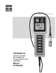
YSI 550A
Handheld
Dissolved
Oxygen and
Temperature
System
Service
Manual
CONTENTS
SECTION 1
SERVICE PHILOSOPHY .......................................................................................................3
SECTION 2
PRINCIPLES OF OPERATION.............................................................................................3
SECTION 3
SPECIFICATIONS...................................................................................................................5
SECTION 4
PREPARING THE PROBE.....................................................................................................6
4.1
4.2
4.3
4.4
4.5
4.6
4.7
DESCRIPTION .........................................................................................................................................6
CHOOSING THE RIGHT MEMBRANE ......................................................................................................6
PROBE PREPARATION ............................................................................................................................6
MEMBRANE CAP INSTALLATION ...........................................................................................................6
PROBE OPERATION AND PRECAUTIONS.................................................................................................7
PROBE MAINTENANCE ..........................................................................................................................8
HOW TO REPLACE THE DO PROBE TIP ..................................................................................................9
SECTION 5
5.1
5.2
CALIBRATION ......................................................................................................................11
BEFORE YOU CALIBRATE ....................................................................................................................11
THE CALIBRATION PROCESS ...............................................................................................................11
SECTION 6
TROUBLESHOOTING .........................................................................................................14
SECTION 7
DISSASEMBLY/ASSEMBLY PROCEDURE...................................................................15
7.1
7.2
7.3
7.4
7.5
7.6
DISASSEMBLY......................................................................................................................................15
ASSEMBLY ...........................................................................................................................................16
ASSEMBLY DRAWING ..........................................................................................................................20
BOARD ASSEMBLY ..............................................................................................................................21
CIRCUIT DIAGRAM...............................................................................................................................22
CIRCUIT BOARD PARTS LIST ...............................................................................................................23
SECTION 8
8.1
8.2
8.3
TEST PROCEDURES ............................................................................................................24
SYSTEM FUNCTIONALITY TEST ...........................................................................................................24
PROBE TEST.........................................................................................................................................24
TEST PROCEDURES ..............................................................................................................................25
SECTION 9
WARRANTY AND REPAIR.................................................................................................26
APPENDIX A
REQUIRED NOTICE........................................................................................................31
APPENDIX B
ACCESSORIES/REPLACEMENT PARTS ...................................................................32
i
ii
SECTION 1 SERVICE PHILOSOPHY
The YSI 550A DO Instrument is sold as a complete dissolved oxygen measuring system including
an attached probe and a 12, 25, 50 or 100 foot cable. Most service issues that occur in dissolved
oxygen systems are caused by improper maintenance of the probe or cable. For this reason,
troubleshooting efforts should be initially directed at determining the condition and function of the
probe and cable.
In the event that a service problem is isolated to the instrument itself, YSI recommends the
replacement of the entire defective sub-assembly rather than individual components. All
replacement systems are available through YSI; see Section 9, Warranty & Repair for details.
SECTION 2 PRINCIPLES OF OPERATION
The sensor consists of a silver body as the anode and a circular gold cathode embedded in the end.
In operation, this end of the sensor is filled with a solution of electrolyte containing a small amount
of surfactant to improve wetting action.
A thin semi-permeable membrane, stretched over the sensor, isolates the electrodes from the
environment, while allowing gases to enter. When a polarizing voltage is applied to the sensor
electrodes oxygen that has passed through the membrane reacts at the cathode causing a current to
flow.
The membrane passes oxygen at a rate proportional to the pressure difference across it. Since
oxygen is rapidly consumed at the cathode, it can be assumed that the oxygen pressure inside the
membrane is zero. Hence, the force causing the oxygen to diffuse through the membrane is
proportional to the partial pressure of oxygen outside the membrane. As the oxygen partial pressure
varies, so does the oxygen diffusion through the membrane. This causes the probe current to change
proportionally.
It is important to recognize that oxygen dissolved in the sample is consumed during the test. It is
therefore essential that the sample be continuously stirred at the sensor tip. If stagnation occurs,
your readings will be artificially low. Stirring may be accomplished by mechanically moving the
sample around the probe tip, or by rapidly moving the probe through the sample. The rate of stirring
should be at least 0.5 foot per second.
DISCUSSION OF MEASUREMENT ERRORS
There are three basic types of dissolved oxygen errors. Type 1 errors are related to limitations of
instrument design and tolerances of instrument components. These are primarily the instrument
linearity and the resistor tolerances. Type 2 errors are due to basic probe accuracy tolerances,
mainly background signal, probe linearity, and variations in membrane temperature coefficient.
Type 3 errors are related to the operator's ability to determine the conditions at the time of
calibration. If calibration is performed against more accurately known conditions, type 3 errors are
appropriately reduced.
YSI Incorporated
YSI 550A DO Handheld Instrument
3
TYPE 1 ERRORS
•
•
Instrument linearity error: ±1% of full scale reading, or ±0.15 mg/L
Component and circuitry error: ±0.05 mg/L
TYPE 2 ERRORS
•
•
DO errors caused by temperature compensation for measurements at ±10°C from calibration
temperature: ±1% (0.08 mg/L at 25°C)
DO errors caused by temperature measurement errors: A maximum ±0.2°C temperature error is
equal to ±0.5% (0.04mg/L at 25°C).
TYPE 3 ERRORS
•
•
•
•
Altitude
Operator Error:
A 1000 feet error in altitude (when calibrating) is equal to an error of
approximately 3.6% at the 10 mg/L level.
Instrument Error:
The maximum DO error caused by calibrating to altitude in increments
of 100 feet: ±0.18% (< 0.015 mg/L at 25°C)
Humidity:
Errors occur if calibration is performed at less than 100% humidity.
The worst possible case would be calibration at 0% humidity. The error varies with the calibration
temperature as follows:
Temperature
Calibration Error at 0% humidity
0oC
0.09 mg/L
10oC
0.14 mg/L
20oC
0.21 mg/L
30oC
0.33 mg/L
40oC
0.50 mg/L
APPROXIMATING THE ERROR
It is unlikely that the actual error in any measurement will be the maximum possible error. A better
error approximation is obtained using a root mean squared (r.m.s.) calculation:
r.m.s. error = ±[1a2 + 1b2 + 2a2 + 2b2 + 3a2 + 3b2]½ mg/L
NOTE: This sample calculation is for a near extreme set of conditions.
YSI Incorporated
YSI 550A DO Handheld Instrument
4
SECTION 3 SPECIFICATIONS
Display
Resolution
Range
Accuracy
Dissolved O2 mg/L
0.01 mg/L or 0.1 mg/L,
user selectable
0 to 20 mg/L
Dissolved O2 %
0.1% or 1%, user
selectable
± 0.3 mg/L or ± 2% of reading,
whichever is greater
± 6% of reading
± 2% air sat or ± 2% of reading,
whichever is greater
± 6% of reading
± 0.3 ºC
± 0.6 ºF
Temperature ºC
Temperature ºF
0.1 ºC
0.1 ºF
Medium:
Dissolved Oxygen Sensor:
Dissolved Oxygen Probe:
Dissolved Oxygen Response Time:
Temperature Units:
Parameter Compensation:
Size:
Weight with Batteries:
Power:
Battery life:
Cables:
Other Features:
YSI Incorporated
20 to 50 mg/L
0 to 200%
200 to 500%
-5 to +45 ºC
23 to 113 ºF
Fresh, sea or polluted water
Steady-state polarographic
Field-replaceable module
95% of end value in 9 seconds
Celsius or Fahrenheit, user selectable
Automatic temperature compensation for dissolved oxygen
Automatic salinity compensation (0-70 ppt) for dissolved oxygen
Altitude compensation for dissolved oxygen percent calibration
4.7 in. width; 9 in. length (11.9 cm x 22.9 cm)
2 lb. (0.91 kg)
4 alkaline C-cells
Over 2000 hours at 25°C (77ºF)
12, 25, 50, and 100-foot lengths
(3.5, 7.5, 15, 30.5 meter lengths)
Waterproof to IP-67
High-impact resistance
Push-button calibration
Built-in calibration chamber
Large back-lit display
Low battery indicator on display
Manual salinity input
CE-compliance
YSI 550A DO Handheld Instrument
5
SECTION 4 PREPARING THE PROBE
4.1
DESCRIPTION
The YSI 550A dissolved oxygen probe is a replaceable, polarographic sensor designed specifically
for the YSI 550A Handheld Dissolved Oxygen System. Probe cables are available in lengths of 12,
25, 50 and 100 feet. See Figure 1.
Figure 1
4.2
CHOOSING THE RIGHT MEMBRANE
The YSI 5908 Membrane Kit is supplied with the YSI 550A DO Instrument. This kit contains six
cap membranes and a bottle of electrolyte solution. The 5908 Membrane Kit is the ONLY kit
suitable for the 550A.
4.3
PROBE PREPARATION
The YSI 550A DO probe is shipped dry. Before using the YSI 550A, the protective membrane
cap on the probe tip must be removed, the new membrane cap must be filled with electrolyte
solution and installed. Follow the instructions below to replace the membrane cap.
4.4
MEMBRANE CAP INSTALLATION
To install a new membrane cap on your YSI 550A dissolved oxygen probe:
1. Unscrew and remove the probe sensor guard.
2. Unscrew and remove the old membrane cap.
YSI Incorporated
YSI 550A DO Handheld Instrument
6
3.
4.
5.
6.
Thoroughly rinse the sensor tip with distilled or DI water.
Prepare the electrolyte according to the directions on the KCl solution bottle.
Hold the membrane cap and fill it at least 1/2 full with the electrolyte solution.
Screw the membrane cap onto the probe moderately tight. A small amount of electrolyte should
overflow.
7. Screw the probe sensor guard on moderately tight.
CAUTION: Do not touch the membrane surface.
4.5
PROBE OPERATION AND PRECAUTIONS
NOTE: The YSI 550A DO Instrument should not be used in a purpose other than that specified
by YSI Incorporated. See Section 9, Warranty and Repair for details.
1.
It is important to recognize that oxygen dissolved in the sample is consumed during probe
operation. It is therefore essential that the sample be continuously stirred at the sensor tip. If
stagnation occurs, your readings will be artificially low. Stirring may be accomplished by
mechanically moving the sample around the probe tip, or by rapidly moving the probe through
the sample. The rate of stirring should be at least .5 foot per second.
2.
Membrane life depends on usage. Membranes will last a long time if installed properly and
treated with care. Erratic readings are a result of loose, wrinkled, damaged, fouled membranes,
or from large (more than 1/8" diameter) bubbles in the electrolyte reservoir. If erratic readings
or evidence of membrane damage occurs, you should replace the membrane and the electrolyte
solution. The average replacement interval is two to four weeks.
3.
If the membrane is coated with oxygen consuming (e.g. bacteria) or oxygen producing
organisms (e.g. algae), erroneous readings may occur.
4.
Chlorine, sulfur dioxide, nitric oxide, and nitrous oxide can affect readings by behaving like
oxygen at the probe. If you suspect erroneous readings, it may be necessary to determine if
these gases are the cause.
5.
Avoid any environment that contains substances that may attack the probe materials. Some of
these substances are concentrated acids, caustics, and strong solvents. The probe materials that
come in contact with the sample include PE (Polyethylene), acrylic plastic, EPR rubber,
stainless steel, epoxy, polyetherimide and the PVC cable covering.
6.
For correct probe operation, the gold cathode must always be bright. If it is tarnished (which
can result from contact with certain gases), or plated with silver (which can result from
extended use with a loose or wrinkled membrane), the gold surface must be restored. To
restore the cathode, you may either return the instrument to the factory or clean it using the
sanding disk in the YSI 5238 Probe Reconditioning Kit. Never use chemicals or abrasives not
supplied with this kit.
YSI Incorporated
YSI 550A DO Handheld Instrument
7
7.
It is also possible for the silver anode, which is the entire silver body of the probe, to become
contaminated, which will prevent successful calibration. To clean the anode, follow the Anode
cleaning instructions in the following section. Next, rinse the sensor tip and Electrolyte
reservoir with deionize water, add new Electrolyte solution, and install a new membrane and
O-ring. Turn the instrument on and allow the system to stabilize for at least 30 minutes. If,
after several hours, you are still unable to calibrate, return the YSI 550A DO Instrument to a
YSI authorized service center for service, See Section 9, Warranty and Repair for more
information.
8.
To keep the electrolyte from drying out, store the probe in the calibration/storage chamber with
the wet sponge.
4.6
PROBE MAINTENANCE
ELECTRODE CLEANING
It is always a good practice to keep the probe in good operating condition.
SILVER ANODE
After extended use, a thick layer of AgCl builds up on the silver anode reducing the sensitivity of
the sensor. The anode must be cleaned to remove this layer and restore proper performance. The
cleaning can be chemical or mechanical:
•
Chemical cleaning: Remove the membrane cap and soak the entire anode section in a
14% ammonium hydroxide solution for 2 to 3 minutes, followed by a thorough rinsing
with distilled or deionize water. The anode should then be thoroughly wiped with a wet
paper towel to remove the residual layer from the anode.
•
Mechanical cleaning: Sand off the dark layer from the silver anode with 400 grit wet/dry
sandpaper. Wrap the wet sandpaper around the anode and twist the probe. Rinse the anode
with clean water after sanding, followed by wiping thoroughly with a wet paper towel.
GOLD CATHODE
For correct probe operation, the gold cathode must be textured properly. It can become tarnished or
plated with silver after extended use. The gold cathode can be cleaned by using the adhesive backed
sanding disc and tool provided in the YSI 5238 Probe Reconditioning Kit.
Using the sanding paper provided in the YSI 5238 Probe Reconditioning Kit, wet sand the gold
with a twisting motion about 3 times or until all silver deposits are removed and the gold appears to
have a matte finish. If the cathode remains tarnished, return the probe for service. Wipe the gold
cathode thoroughly with a wet paper towel before putting on a new membrane cap.
YSI Incorporated
YSI 550A DO Handheld Instrument
8
4.7
HOW TO REPLACE THE DO PROBE TIP
The YSI 559 Replaceable DO Module Kit includes:
Quantity
Item
1
Instruction Sheet
1
Sensor, DO Module
1
Set Screw 4-40x 1/2 long
1
Hex key Wrench, .050”
DO SENSOR REPLACEMENT
Along with the YSI 559 dissolved oxygen module, YSI supplies a set screw that holds the sensor in
place, a hex key wrench to help install the probe, and an instruction sheet. See Figure 6.
1. Remove probe guard.
2. IMPORTANT: Thoroughly dry the sensor so that no water enters the probe port when the
sensor is removed.
3. Insert the long end of the hex key wrench into the small hole in the side of the DO sensor
module (see figure 2). Turn the wrench counter clockwise and remove the screw. (You do not
have to remove the screw all the way to release the sensor.)
4. Pull the DO sensor out of the module. The DO sensor is keyed, or has a flat side, so that it can
not be removed improperly.
5. Insert the new probe. Make sure that the inside of the module and the o-ring of the sensor are
clean, with no contaminants, such as grease, dirt, or hair. The DO sensor is keyed, or has a flat
side, so that it can not be installed improperly.
6a. IF you did not remove the screw all the way in Step 3: Use the hex key wrench to tighten the
screw in properly, making sure that the screw does not stick out on either side of the DO sensor
module.
6b. IF you removed the screw all the way in Step 3: Insert the set screw into the small hole in the
side of the DO sensor module, and turn clockwise to rethread.
Probe Guard
DO Sensor
Set Screw
Cable End
Hex Key
Wrench
Figure 2
YSI Incorporated
YSI 550A DO Handheld Instrument
9
7. The YSI 559 DO module is shipped dry. Before using the YSI 550A with a new YSI 559
sensor, the protective membrane on the probe tip must be removed, the membrane cap
must be filled with electrolyte solution and a new membrane must be installed. Follow the
instructions below to install the electrolyte solution and membrane.
CAUTION: Make sure that you do not cross-thread the screw. Use the hex key wrench to
tighten the screw in properly, making sure that the screw does not stick out on either side of
the cable end. The probe guard will not thread on properly and damage may result if the
screw is allowed to stick out on either side of the cable end.
YSI Incorporated
YSI 550A DO Handheld Instrument
10
SECTION 5 CALIBRATION
Dissolved oxygen calibration must be done in an environment with a known oxygen content.
Since the amount of oxygen in the atmosphere is known, it makes an excellent environment for
calibration (at 100% relative humidity). The calibration/storage chamber contains a sponge to
create a 100% water saturated air environment.
5.1
BEFORE YOU CALIBRATE
Before you calibrate the YSI 550A DO Instrument complete the procedures discussed in Section 2,
Preparing the YSI 550A and Section 3, Preparing the Probe. You can calibrate the YSI 550A
DO Instrument in either mg/L or % saturation. In the section below, you will find instructions on
how to calibrate and change between these modes.
Note: While testing to EN-61000-4-6, Conducted RF Immunity, per Table A.1 of EN61326,
Electrical Equipment for Measurement, Control and Laboratory Use, the YSI 550A exhibited an
ERROR 8 message from 8.6 MHz 22.8 MHz at induced RF voltages of 3-Volts to 1-Volt RMS on
the 25-foot probe cable. If you observe this interference please relocate the probe-cable away from
heavy industrial equipment power and control cables or communications equipment cables which
may be causing the interference.
To accurately calibrate the YSI 550A, you will need to know the following information:
! The approximate salinity of the water you will be analyzing. Fresh water has a salinity of
approximately zero. Seawater has a salinity of approximately 35 parts per thousand (ppt). If you
are uncertain what the salinity of the sample water, use a YSI 30 Salinity-ConductivityTemperature instrument to determine salinity.
! IF you are going to calibrate in % saturation mode, you need to know the approximate altitude
of the region where you are located.
5.2
THE CALIBRATION PROCESS
1.
Ensure that the sponge inside the instrument's calibration chamber is moist. Insert the probe
into the calibration chamber.
2.
Turn the instrument on by pressing the ON/OFF button on the front of the instrument. Wait
for the dissolved oxygen and temperature readings to stabilize (usually 15 minutes is required
after turning the instrument on).
Note: You must choose to calibrate in mg/L or % saturation mode. Once you are in the calibration
menu, you can switch between % saturation and mg/L.
To switch between mg/L and % saturation to be displayed as the oxygen readings units, press the
Mode key. Either a “mg/L” or “%” will be displayed on the right side of the screen.
YSI Incorporated
YSI 550A DO Handheld Instrument
11
3.
To enter the calibration menu, use two fingers to press and release both the UP ARROW and
DOWN ARROW keys at the same time.
TO CALIBRATE IN MG/L:
Place the probe in solution with a known mg/L reading. You must agitate or stir the probe with a
rate of at least .5 foot per second during the entire calibration process.
4.
Make sure that the DO reading (large display) is stable, then press the ENTER button. The
YSI 550A DO instrument should now display CAL in the lower left of the display and the
current DO reading (before calibration) should be on the main display.
5.
Using the up and down arrow keys, select the mg/L value of the known solution, then press the
ENTER button. The LCD will prompt you to enter the approximate salinity of the water you
are about to analyze. You can enter any number from 0 to 70 parts per thousand (PPT) of
salinity. Use the arrow keys to increase or decrease the salinity setting. When the correct
salinity appears on the LCD (zero for fresh water), press the ENTER key. The instrument will
return to normal operation.
Once the calibration process is complete, the only keys that will remain operational are the MODE
key, the LIGHT key and the ON/OFF key. You can move back and forth from reading dissolved
oxygen in the mg/L mode or the % air saturation mode by pressing the MODE key. If you are
working in a dark area and have difficulty reading the LCD, press the LIGHT key to activate the
back-light of the YSI 550A. The ON/OFF key turns the instrument on or off.
For best results:
! Each time the YSI 550A DO Instrument is turned off, re-calibrate before taking measurements.
! Calibrate at a temperature within ±10°C of the sample temperature.
TO CALIBRATE IN % SATURATION:
To switch between mg/L and percent saturation to be displayed as the oxygen readings units, press
the Mode key. Either a “mg/L” or “%” will be displayed on the right side of the screen.
4.
IF you are calibrating in % saturation mode, the LCD will prompt you to enter the local
altitude in hundreds of feet. Use the arrow keys to increase or decrease the altitude.
EXAMPLE: Entering the number 12 here indicates 1200 feet.
5.
When the proper altitude appears on the LCD, press the ENTER key. The YSI 550A DO
Instrument should now display CAL in the lower left of the display, the calibration value
should be displayed in the lower right of the display and the current DO reading (before
calibration) should be on the main display.
6. Make sure that the DO reading (large display) is stable, then press the ENTER button. The
LCD will prompt you to enter the approximate salinity of the water you are about to analyze.
YSI Incorporated
YSI 550A DO Handheld Instrument
12
You can enter any number from 0 to 70 parts per thousand (PPT) of salinity. Use the arrow
keys to increase or decrease the salinity setting. When the correct salinity appears on the LCD
(zero for fresh water), press the ENTER key. The instrument will return to normal operation.
Once the calibration process is complete, the only keys that will remain operational are the MODE
key, the LIGHT key and the ON/OFF key. You can move back and forth from reading dissolved
oxygen in the mg/L mode or the % air saturation mode by pressing the MODE key. If you are
working in a dark area and have difficulty reading the LCD, press and hold the LIGHT key to
activate the back-light of the YSI 550A. The ON/OFF key turns the instrument on or off.
For best results:
Each time the YSI 550A DO Instrument is turned off, re-calibrate before taking measurements.
! Calibrate at a temperature within ±10°C of the sample temperature.
YSI Incorporated
YSI 550A DO Handheld Instrument
13
SECTION 6 TROUBLESHOOTING
NOTE: An error displayed briefly during the first few seconds after turning the instrument
on does NOT indicate a problem.
SYMPTOM
POSSIBLE SOLUTION
1. Instrument will not turn on,
LCD displays "LO BAT", or
Main display flashes “OFF”
A. Low battery voltage, replace batteries
B. Batteries installed incorrectly, check battery polarity
C. Return system for service
2. Instrument will not calibrate.
A. Replace membrane and electrolyte
B. Clean probe electrodes
C. Return system for service
3. Instrument "locks up".
A. Remove batteries, wait 15 seconds for reset, replace batteries
B. Replace batteries
C. Return system for service
4. Instrument readings are
inaccurate.
A. Verify calibration altitude and salinity settings are correct and
recalibrate.
B. Probe may not have been in 100% water saturated air during
calibration procedure. Moisten sponge in calibration chamber
and recalibrate.
C. Replace membrane and electrolyte. Recalibrate.
D. Clean probe electrodes.
E. Return system for service.
5. Main display reads “Over” or
“Undr”.
A. Sample O2 concentration is more than 60 mg/L or 500%, or less
than –0.02 mg/L or -0.3%.
B. Verify calibration altitude and salinity settings are correct and
recalibrate.
C. Replace membrane and electrolyte. Recalibrate.
D. Clean probe electrodes.
E. Return system for service.
6. Main display reads “Over” or
“Undr” during calibration.
A. Replace membrane and electrolyte. Recalibrate.
B. Clean probe electrodes.
C. Return system for service.
7. Secondary display reads
"Ovr" or “Undr”.
A. Sample temperature is less than -5º C (23ºF) or more than
+45oC (122oF). Increase or decrease the sample temperature to
bring within the allowable range.
B. Return system for service.
8. Main display reads “Err” and
Secondary display reads
“RO”, “RA”, or “AdC”.
9. Main display reads “Err” or
burn” and
Secondary display reads
“EEP”
A. Return system for service
YSI Incorporated
YSI 550A DO Handheld Instrument
A. Return system for service
14
SECTION 7 DISSASEMBLY/ASSEMBLY
PROCEDURE
Tools Required:
• Torque screwdriver , 6.8 in-lbs
• Torque wrench, 12 in-lbs
• Torx T15 bit (long shank)
• Phillips screwdriver
Due to the YSI 550A’s waterproof design, it is critical that care be taken during the disassembly and
assembly process. Refer to Section 7.2, Assembly Drawing while attempting this procedure.
7.1
DISASSEMBLY
Step 1 -- Place the instrument face down on a flat cloth-covered surface. Use a Phillips screwdriver
to loosen the 4 battery lid screws. Remove the battery lid and 4 “C” batteries.
Step 2 -- With the instrument face down on the flat, cloth-covered surface, remove the 6- 6-32 x 1
Torx screws Pull straight up on the battery chamber to separate the case halves.
TORX screw
locations
PCB REMOVAL
Step 1 -- The main PC Board is held in place by a
single Phillips screw located in the center of the
board. Remove the screw, and gently pull the PC
board away from the front case.
Step 2 -- Carefully slide the probe connectors out
of the mating PCB connector. Make note of the
YSI Incorporated
YSI 550A DO Handheld Instrument
15
wire color configuration so that the connectors can be correctly re-installed later.
PROBE CABLE REMOVAL
Step 1 -- To separate the probe cable from the front case, unscrew the outer portion of the strain
relief (that portion which does not make contact with the case). Slide the spiral portion of the strain
relief down the cable toward the probe. Next, unscrew the remaining portion of the strain relief
from the front case and pull the wires and connectors through the threaded hole.
LCD REMOVAL
Step 1 -- To separate the LCD assembly from the main PC Board, remove the four Phillips
mounting screws.
7.2
ASSEMBLY
PROBE CABLE INSTALLATION
Step 1 -- Feed the cable through the threaded hole in the strain relief adapter. Attach the amp
connectors of the cable to the 550A Board Assembly. Double check the wire colors. Be sure the
connectors are completely installed (they should not stick out past the PCB edge).
3 Pin Conn.
2 Pin
Conn.
Step 2 -- Hold the cable so that its outer jacket is visible inside the case. Thread the strain relief
main nut into the adapter. Hand-tighten, then torque to 12 in – lbs.
Step 3 -- Hold the cable with one hand. Use the other hand to thread the relief nut onto the back of
the main nut. Hand-tighten, then torque to 12 in - lbs.
YSI Incorporated
YSI 550A DO Handheld Instrument
16
Outer
jacket
visible
Main nut
Relief nut
PCB REPLACEMENT/INSTALLATION
Step 1 -- Position the PCB onto the rear case locating posts. The case center-mounting hole should
be visible through the center hole in the PCB. Fasten the PCB to the case using screw (655154).
Rear case locating
Center hole in PCB,
under screw (655154)
Step 2 -- Remove the protective film from the PCB display and discard.
Step 3 -- Install the display shock mount onto the PCB display. Locate the ribs on the under side of
the shock mount, one on each short edge. Be sure the ribs engage the slots on either side of the
clear plastic display retainer.
Silver strip
Rib on short edge
Slot in clear plastic retainer
YSI Incorporated
Protective film to be
removed
YSI 550A DO Handheld Instrument
17
CASE ASSEMBLY
Whenever the YSI 550A’s case is opened; 1) All gaskets and seals need to be clean and free
of dirt or dust. 2) Proper torque specs must be followed to ensure a watertight seal.
Step 1 -- Verify that the (6ea) Mounting hole gaskets and (2ea ) PCB Backer shock mounts are in
place.
Step 2 – Inspect the lens on the front cover, display lens and gaskets and be certain they are free
from dust or lint.
(6) Mounting hole gaskets
(2) PCB Backer shock
mounts
Be sure all gaskets are clean before proceeding. Debris on the gaskets could cause the case
to leak.
Step 3 -- Double-check the main case
gasket for proper
Shock mount installs with
seating and then
its lip at the top
mate the rear case
assembly to the
front case. You
Mounting hole gasket
will need to locate
installs with its lip at the
the bails in the
proper holes on the
rear case as you mate the cases.
YSI Incorporated
YSI 550A DO Handheld Instrument
18
Step 4 -- Fasten the case halves together using (6ea) Torx screws and torque screw driver set to 6.8
in – lbs.
Proper groove in
front case
Main case gasket
Extra important
area
Step 5 -- Install new warranty protection label
YSI Incorporated
YSI 550A DO Handheld Instrument
19
7.3
ASSEMBLY DRAWING
Bubble Number
1
2
3
4
5
6
7
8
9
10
11
11
11
11
12
13
YSI Incorporated
Item Number
115525
115524
605351
115521
115523
655148
055219
655157
655155
655152
115158
115159
115160
115161
655137
655154
Description
Front Cover Assembly W/Keypad
Display Parts Kit
PC Board Assembly W/Display
Rear Case Assembly
Battery Lid Assembly W/Screws
Probe Storage Chamber
Sponge
Rubber Plug
(2) ¼-20 Phillips Round Machine Screws
(6) 6-32 x 1 Lg Pan Head Torx Screws
Cable assembly, 12 ft
Cable assembly, 25 ft
Cable assembly, 50 ft
Cable assembly, 100 ft
Handstrap Bail
4-20 x ¼ Lg PCB Screw
YSI 550A DO Handheld Instrument
20
7.4
BOARD ASSEMBLY
FRONT
REAR
YSI Incorporated
YSI 550A DO Handheld Instrument
21
7.5
CIRCUIT DIAGRAM
YSI Incorporated
YSI 550A DO Handheld Instrument
22
7.6
CIRCUIT BOARD PARTS LIST
CIRCUIT SYMBOL DESCRIPTION
QTY.
J1+,J1J2
J3,J4
R1
R2
R3
R4,R6
R5,R8
R7
R9,R11,R12,R19,R22,R27,R29
R10
R13
R14
R15,R18
R16
R17
R20
R21
R23
R24
R25
R26
R28
R30
RN1
L1
L2,L3,L4,L6
L5
C1,C3,C6
C2,C10,C11,C22,C23
C4,C21
C5,C19
C7
C8,C13
C9,C14,C16,C18,C20,C24~C28
C12
C15,C17
C29,C30
X1
Q1,Q2
U1
U2
U3
U4
U5
U6
U7
U8
U9
U10
U11
U12
U13
SW1~SW6
D1
D2~D8,D17~D22
D9~D14
D23
CONN. 70ADH002-ML0
CONN. 5 PIN. RT. ANGLE
CONN. 3 PIN. RT. ANGLE
RES. 10K,5%,1/4W
RES. 54.9K,1%,1/4W
RES. 100K,1%,1/4W
RES. 10K,1%,1/4W
RES. 1K,1%,1/4W
RES. 15.8K,1%,1/4W
RES. 100K,5%,1/4W
RES. 6.81K,0.1%,1/4W
RES. 220K,5%,1/4W
RES. 127K,1%,1/4W
RES. 1.5K,5%,1/4W
RES. 27,5%,1/4W
RES. 1.2K,5%,1/4W
RES. 402K,1%,1/4W
RES. 205K,1%,1/4W
RES. 450K,1%,1/4W
RES. 249K,1%,1/4W
RES. 357K,1%,1/4W
RES. 68K,5%,1/4W
RES. 1M,5%,1/4W
RES. 10M,5%,1/4W
RES. SIP. 100K
BEAD FR2943666681
INDUCTOR. 10uH,1/4W
INDUCTOR. 150uH,1/4W
CAPR. ELE. 100uF,16V
CAPR. MPE. 0.1uF,63V
CAPR. MPE. 0.47uF,63V
CAPR. ELE. 10uF,16V
CAPR. ELE. 2.2uF,16V
CAPR. CER. 100pF,50V
CAPR. MULTI. 0.1uF,50V
CAPR. MPE. 0.33uF,63V
CAPR. MPE. 1uF,63V
CAPR. CER. 20pF,50V
CRYSTAL 2.000M Hz
TRSTR. C945P
I.C. TI TPS76133DBVT
I.C. TLDN. TSC7660CPA
I.C. NATL LM385-1.2
I.C. AMP OP290GP
I.C. NATL. CD4053BCN
I.C. AME AME8800AEFT
I.C. TOSH. TC4011BP
I.C. TLDN. TSC500CPE
I.C. NATL. LM358N
I.C.MOTOR.MC68HC705C8ACP
I.C. OKI M5265 0082352-B
I.C. EXCL. XLS93C46P
I.C. SEIKO. S80730AL
TACT SW. KDTSM62N-GS
DIODE, 1N5817
DIODE, 1N4148
LED LAMP,HLMP-1540
DIODE, 1N60
YSI Incorporated
YSI 550A DO Handheld Instrument
2
1
0.2
1
1
1
2
2
1
7
1
1
1
2
1
1
1
1
1
1
1
1
1
1
1
1
4
1
3
5
2
2
1
2
10
1
2
2
1
1
1
1
1
1
1
1
1
1
1
1
1
1
1
6
1
13
6
1
23
SECTION 8 TEST PROCEDURES
8.1
SYSTEM FUNCTIONALITY TEST
The Model 550A can be easily tested using the DO4 Test Box or resistance decade boxes. If a test
box isn’t available, the following quick test can be used to verify the system’s operation.
1. If necessary, service the probe’s electrodes.
2. Install a fresh membrane and probe solution. Place the probe in its calibration chamber.
3. Turn the system on and allow it to stabilize for 15-30 minutes.
4. Calibrate the system as described in the Calibration section of this manual.
5. With the probe in the calibration chamber, check the displayed reading for stability. Erratic or
drifting readings indicate a possible problem. See the Troubleshooting section for help.
6. Place the probe in a zero oxygen environment. The display should decrease rapidly and reach 0
±2% in 5 minutes or less.
A zero oxygen environment can be obtained by taking a reading in pure nitrogen gas or in a sodium
sulfite solution. It can also be obtained in a BOD bottle filled with 350 mL of distilled water in
which 3 to 7 grams of active dry yeast has been dissolved and allowed to consume the oxygen
(about 5 minutes).
8.2
PROBE TEST
The probe thermistor can be tested by measuring its resistance in a
temperature controlled bath and comparing the reading to the chart
below. With the probe disconnected from the instrument, connect a
precision ohm meter to the Red and Black probe wires. All
readings are ± 10 ohms.
Bath temperature
Celsius
Resistance in
Ohms
0
32.66 K
10
19.90 K
25
10.00 K
Red
Black
Shield
40
White
5329.0
Green
Electrical leakage between the sensor electrodes and/or the
thermistor can cause system failure. Before using the test below, remove the probe’s membrane and
rinse the electrodes with distilled water. Then, thoroughly dry the sensor end with compressed air or
a soft towel.
Ohm Meter Lead #1
Green (silver anode)
YSI Incorporated
Ohm Meter Lead #2
White (gold cathode)
YSI 550A DO Handheld Instrument
Resistance Reading
200 meg ohm or greater
24
Green (silver anode)
White (gold cathode)
Green, White, Red
8.3
Red (thermistor)
Red (thermistor)
Stainless steel probe body
200 meg ohm or greater
200 meg ohm or greater
200 meg ohm or greater
TEST PROCEDURES
As stated in the Service Philosophy section of this manual, the best way to troubleshoot the Model
550A is by subassembly substitution. Below are procedures to test the accuracy and function of the
instrument’s circuits. If any section of the test fails, the board assembly or probe will have to be
repaired or replaced.
TEMPERATURE CIRCUIT TEST
Disassemble the instrument case by following the Disassembly Procedure section of this manual.
The temperature circuit can be tested by substituting the probe thermistor at connector J2, pins 4
and 5 with a decade resistance box or by using the DO4 test
box (Sub for Red and Black probe wires).
Resistance Input
J2 Pins 4 & 5
32.66 KΩ ± .1%
19.90 KΩ ± .1%
10.00 KΩ ± .1%
5329 Ω ± .1%
Acceptable
Displayed Reading
0.0 oC ± .1 oC
10.0 oC ± .1 oC
25.0 oC ± .1 oC
40.0 oC ± .1 oC
Red
DISSOLVED OXYGEN CIRCUIT TEST
Black
Shield
Green
White
Perform this test using a DO4 Test Box, or by using a decade
resistance box connected to J2 pins 1 & 2 (Sub for Green and White probe wires) and input the
resistance values in column 2. To begin the test, input the resistance value (in chart above) for
25.0 oC and input the resistance of Row #1. Calibrate to 100.0 %, Salinity set to 0.0 ppt.
NOTE: Last setting is with a temperature resistance value of 10.0 oC.
Input to connector J2, Pins 1 &2
Set temperature
Resistor input:
to report:
25.0 oC
111.42 K Ω ±0.1%
25.0 oC
250.0 K Ω ±0.1%
o
25.0 C
2.04 M Ω ±1%
25.0 oC
Infinity
o
10.0 C
88.2 K Ω ±0.1%
YSI Incorporated
Display Reading
(% Mode)
100.0 ±0.1%
44.6 ±0.2%
5.5 ±0.2%
0.0 +1.0%
296.4 ±0.2%
YSI 550A DO Handheld Instrument
Display Reading
(Mg/L Mode)
8.26 ±0.02 Mg/L
3.68 ±0.02 Mg/L
0.45 ±0.02 Mg/L
0.00 ±0.1 Mg/L
33.46 ±0.02 Mg/L
25
SECTION 9 WARRANTY AND REPAIR
The YSI 550A DO Instrument is warranted for three years from date of purchase by the end user
against defects in materials and workmanship. YSI 550A DO probes and cables are warranted for
one year from date of purchase by the end user against defects in material and workmanship. Within
the warranty period, YSI will repair or replace, at its sole discretion, free of charge, any product that
YSI determines to be covered by this warranty.
To exercise this warranty, write or call your local YSI representative, or contact YSI Customer
Service in Yellow Springs, Ohio. Send the product and proof of purchase, transportation prepaid, to
the Authorized Service Center selected by YSI. Repair or replacement will be made and the product
returned transportation prepaid. Repaired or replaced products are warranted for the balance of the
original warranty period, or at least 90 days from date of repair or replacement.
Limitation of Warranty
This Warranty does not apply to any YSI product damage or failure caused by (i) failure to install,
operate or use the product in accordance with YSI’s written instructions, (ii) abuse or misuse of the
product, (iii) failure to maintain the product in accordance with YSI’s written instructions or
standard industry procedure, (iv) any improper repairs to the product, (v) use by you of defective or
improper components or parts in servicing or repairing the product, or (vi) modification of the
product in any way not expressly authorized by YSI.
THIS WARRANTY IS IN LIEU OF ALL OTHER WARRANTIES, EXPRESSED OR IMPLIED,
INCLUDING ANY WARRANTY OF MERCHANTABILITY OR FITNESS FOR A
PARTICULAR PURPOSE. YSI’s LIABILITY UNDER THIS WARRANTY IS LIMITED TO
REPAIR OR REPLACEMENT OF THE PRODUCT, AND THIS SHALL BE YOUR SOLE AND
EXCLUSIVE REMEDY FOR ANY DEFECTIVE PRODUCT COVERED BY THIS
WARRANTY. IN NO EVENT SHALL YSI BE LIABLE FOR ANY SPECIAL, INDIRECT,
INCIDENTAL OR CONSEQUENTIAL DAMAGES RESULTING FROM ANY DEFECTIVE
PRODUCT COVERED BY THIS WARRANTY.
YSI Incorporated
YSI 550A DO Handheld Instrument
26
AUTHORIZED U.S. SERVICE CENTERS
North Region
YSI Incorporated • Repair Center • 1725 Brannum Lane • Yellow Springs, Ohio • 45387
• Phone: (800) 765-4974 • (937) 767-7241• E-Mail: [email protected]
Central Region
Geotech Environmental Equipment, Inc. • 8035 East 40th Ave • Denver, CO • 80207 •
Phone: (303) 320-4764 • Fax: (303) 322-7242
South Region
YSI Environmental, Inc. • 12231 Industriplex Blvd • Suite A • Baton Rouge, LA • 70809
Phone: (866) 216-2662 • (225) 753-2650 • Fax: (225) 753-8669
West Region
EQUIPCO Sales and Service • 2100 Meridian Park Blvd. • Concord, CA • 94520 • Phone:
(800)550-5875 • Fax: (510)674-8655
YSI Incorporated
YSI 550A DO Handheld Instrument
27
INTERNATIONAL AUTHORIZED SERVICE CENTERS
YSI Incorporated • Repair Center • 1725 Brannum Lane • Yellow Springs, Ohio • 45387
• Phone: (937) 767-7241• E-Mail: [email protected]
Hoskin Scientific Ltd. • 4210 Morris Drive • Burlington, ONT., L7L 5L6 • Canada •
Ph: 905-333-5510 • Fax: 905-333-4976 • www.hoskin.ca
Hydrodata Services • Unit 8, Business Centre West, Avenue One • Letchworth • Herts •
SG6 2HB • United Kingdom • Phone: (44-1462) 673581 • Fax: (44-1462) 673582
YSI/Nanotech • Kaizuka 1-15-4 • Kawasaki-Ku, Kawasaki City, Japan • 210-0014 •
Phone: (81-4) 4 3222-0009 • Fax: (81-3) 4 4221-1102 • Email: [email protected]
SPECIALTY AUTHORIZED SERVICE CENTERS
Aquaculture
Aquatic Eco Systems, Inc. • 1767 Benbow Court • Apopka, Florida • Phone: (407) 8863939 • Fax: ( 407) 886-6787
Aquacenter • 166 Seven Oaks Road • Leland, Mississippi • 38756 • Phone: (601) 3782861 • Fax: (601) 378-2862
Wastewater
Q.C. Services • P.O. Box 68 • Harrison, Maine • 04040 • Phone: (207) 583-2980
Q.C. Services • P.O. Box 14831 • Portland, Oregon • 97293 • Phone: (503) 236-2712
North Central Labs • 400 Lyons Road • Birnamwood, Wisconsin • Phone: (800) 648-7836
• Fax: (715) 449-2454
C B & S • P.O. Box 556 • Sycamore, Illinois • 60178 • Phone: (815) 895-5158
Fax: (815) 895-8034
YSI Incorporated
YSI 550A DO Handheld Instrument
28
CLEANING INSTRUCTIONS
NOTE: Before being returned for service, equipment exposed to biological, radioactive, or
toxic materials must be cleaned and disinfected. Biological contamination is presumed for any
instrument, probe, or other device that has been used with body fluids or tissues, or with waste
water. Radioactive contamination is presumed for any instrument, probe or other device that has
been used near any radioactive source.
If an instrument, probe, or other part is returned or presented for service without a Cleaning
Certificate, and if in our opinion it represents a potential biological or radioactive hazard, our
service personnel reserve the right to withhold service until appropriate cleaning, decontamination,
and certification has been completed. We will contact the sender for instructions as to the
disposition of the equipment. Disposition costs will be the responsibility of the sender.
When service is required, either at the user's facility or at YSI, the following steps must be taken to
insure the safety of our service personnel.
1. In a manner appropriate to each device, decontaminate all exposed surfaces, including any
containers. 70% isopropyl alcohol or a solution of 1/4 cup bleach to 1 gallon tap water are
suitable for most disinfecting. Instruments used with wastewater may be disinfected with .5%
Lysol if this is more convenient to the user.
2. The user shall take normal precautions to prevent radioactive contamination and must use
appropriate decontamination procedures should exposure occur.
3. If exposure has occurred, the customer must certify that decontamination has been
accomplished and that no radioactivity is detectable by survey equipment.
4. Any product being returned to the YSI Repair Center, should be packed securely to prevent
damage.
5. Cleaning must be completed and certified on any product before returning it to YSI.
PACKING INSTRUCTIONS
1.
2.
3.
4.
Clean and decontaminate items to insure the safety of the handler.
Complete and include the Cleaning Certificate.
Place the product in a plastic bag to keep out dirt and packing material.
Use a large carton, preferably the original, and surround the product completely with packing
material.
5. Insure for the replacement value of the product.
YSI Incorporated
YSI 550A DO Handheld Instrument
29
Cleaning Certificate
Organization ________________________________
Department _________________________________
Address ___________________________________
City _______________ State ______ Zip ________
Country __________________
Model No. of Device ______ Lot Number _________
Contaminant (if known) _____________________
Cleaning Agent(s) used _____________________
Radioactive Decontamination Certified?
(Answer only if there has been radioactive exposure)
___ Yes ___ No
Cleaning Certified By _________________________
Name
YSI Incorporated
Date
YSI 550A DO Handheld Instrument
30
APPENDIX A
REQUIRED NOTICE
The Federal Communications Commission defines this product as a computing device and requires
the following notice:
This equipment generates and uses radio frequency energy and if not installed and used properly,
may cause interference to radio and television reception. There is no guarantee that interference will
not occur in a particular installation. If this equipment does cause interference to radio or television
reception, which can be determined by turning the equipment off and on, the user is encouraged to
try to correct the interference by one or more of the following measures:
¥ re-orient the receiving antenna
¥ relocate the YSI Instrument with respect to the receiver
¥ move the YSI Instrument away from the receiver
¥ plug the YSI Instrument into a different outlet so that the computer and receiver are on
different branch circuits.
If necessary, the user should consult the dealer or an experienced radio/television technician for
additional suggestions. The user may find the following booklet, prepared by the Federal
Communications Commission, helpful: "How to Identify and Resolve Radio-TV Interference
Problems." This booklet is available from the U.S. Government Printing Office, Washington, DC
20402, Stock No. 0004-000-00345-4.
Note: While testing to EN-61000-4-6, Conducted RF Immunity, per Table A.1 of EN61326,
Electrical Equipment for Measurement, Control and Laboratory Use, the YSI 550A exhibited an
ERROR 8 message from 8.6 MHz 22.8 MHz at induced RF voltages of 3-Volts to 1-Volt RMS on
the 25-foot probe cable. If you observe this interference please relocate the probe-cable away from
heavy industrial equipment power and control cables or communications equipment cables which
may be causing the interference.
YSI Incorporated
YSI 550A DO Handheld Instrument
31
APPENDIX B
ACCESSORIES
REPLACEMENT PARTS
The following parts and accessories are available from YSI or any YSI Authorized Dealer.
YSI Model Number
Description
559
Replacement DO Module
5908
6 Cap Membranes and Electrolyte Solution
5238
5060
5080
5081
Probe Reconditioning Kit (sanding tool and disks for cathode cleaning)
Small Carrying Case, Soft (instrument & 4M cable)
Small Carrying Case, Hard-Sided (instrument & 4M cable)
Large Carrying Case, Hard-Sided (instrument and 20M cable)
5065
Form-Fitted Carrying Case
063507
Tripod
614
Ultra Clamp, C-Clamp Mount
5085
Hands Free Harness
YSI Incorporated
YSI 550A DO Handheld Instrument
32
1700/1725 Brannum Lane
Yellow Springs, Ohio 45387 USA
(800) 765-4974 (937) 767-7241
FAX: (937) 767-1058
Website: http://www.ysi.com
E-mail: [email protected]
Item # 655830
Drawing # 655830
Revision A
November 2003