1
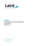
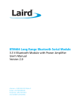
Bluetooth Audio Development
Pack
OKI 7702 Codec Board
User Guide
Part Number ACC-006
The information contained in this document is subject to change without notice. EZURiO Ltd makes no warranty of
any kind with regard to this material including, but not limited to, the implied warranties of merchant ability and
fitness for a particular purpose. EZURiO Ltd shall not be liable for errors contained herein or for incidental or
consequential damages in connection with the furnishing, performance, or use of this material.
© Copyright 2007 EZURiO Limited. All rights reserved.
No part of this document may be photocopied, reproduced, or translated to another language without the prior
written consent of EZURiO.
Bluetooth is a trademark owned by Bluetooth SIG, Inc., USA and licensed to EZURIO Ltd. Other product or company
names used in this publication are for identification purposes only and may be trademarks of their respective
owners.
APN_06003_1v0 OKI Audio Board.DOC
1
Bluetooth® Development Kit
OKI Audio Codec Board
Part Number: ACC-006
1.
General Description
The EZURiO OKI Codec Evaluation Board plugs into the EZURiO Developers kit and allows
you to rapidly test and evaluate Bluetooth audio applications using the EZURiO Bluetooth
Intelligent Serial Module to implement the wireless link.
The ACC-006 evaluation board is based on the OKI 7702 codec - a 3.3V, single channel
codec that supports A-law and μ-law coding. The codec is used to digitise incoming audio
from the microphone into PCM data and convert the PCM digital audio output of the
Bluetooth chip into an analogue signal for the headphones. The codec board has a
microphone input and headphone output which are compatible with standard PC headsets.
The 7702 codec has several features such as power down mode. The ACC-006 codec
evaluation board provides options to allow these features to be tested.
This document provides you with information to prototype and evaluate your own audio
application. Once you have tried out your application, you will be able to design your own
audio solution based around the OKI codec and the EZURiO Bluetooth Intelligent Serial
module.
APN_06003_1v0 OKI Audio Board.DOC
2
2.
Overview
The codec board is powered by an on-board 3.3V regulator to reduce noise to a minimum.
The PCM control signals for the codec go directly to the Bluetooth module on the
motherboard via the 10-way connector, as do the 3 push button switches. This allows the
switches to be used with an external program that implements the upper portion of headset
or Handsfree profile.
The microphone input, designed to interface to PC compatible headsets, has a fixed gain of
10 set by external components to the codec (the amplifier itself is part of the codec). Part of
the microphone signal is mixed into the headphone output signal via VR1. This feature is
known as “sidetone” and allows the user to hear their own voice when speaking. It is
commonly used in telephony applications to give the user the necessary audio feedback that
their ears expect.
The audio output gain is by default fixed at 2.5. By fitting VR2, the audio gain can be made
adjustable.
The 120mW stereo output amplifier U3 ensures that the codec board can drive standard 32Ω
stereo headphones while keeping total harmonic distortion down to 0.1%.
3.
Component Placement
Note that not all
components are fitted –
non-fitted components are
shown without pads. Refer
to Section 7 for details of
component fitment and
specification.
APN_06003_1v0 OKI Audio Board.DOC
3
3.
Codec Board Quick Start Guide
3.1
Getting Started
The codec board is supplied with a right angle, 10 way connector that can be used to connect
it to the main developers kit. If required, this should be soldered to the main board.
Alternatively other connectors or ribbon cables can be used.
3.2
•
•
•
Equipment Required (not supplied)
Headsets (with microphone) (Standard PC headsets are fine)
EZURiO Wireless Developers Kit
BISM II Bluetooth module
Normally two sets of development kit are required to test both ends of an audio link. If an
application is being developed with an existing endpoint, such as a mobile phone or headset,
only one set may be needed.
3.3
Motherboard Jumper Settings
Before using the codec board, there is a jumper setting on the motherboard that needs to be
checked. This is CB1, next to the USB adaptor, which must be removed. If fitted it will
short out the PCM output from the codec and prevent it operating. CB1 is only relevant for
the WLAN 802.11 data module.
REMOVE
3.4
Procedure:
1) Check that SW1 on the codec board is correctly set to the default position (see section
6.3 of this manual).
2) Plug the BISM II into the socket on the Dev Kit, connect to a PC serial port and power up.
See the dev kit manual for different power supply options.
3) Check that AT commands are working using EZURiO terminal. (Refer to blu2i Quick Start
Guide if needed)
4) Power down, plug the codec board into the dev kit and power up. Check that AT
commands are working.
APN_06003_1v0 OKI Audio Board.DOC
4
Configure the Slave unit as follows:
AT&F*
ATZ
ATS103=3
ATS512=4
ATS0=1
ATS531=1
AT&W
ATZ
Restore system defaults
Reset the unit
Set boot mode to OKI Codec A Law
Make connectable and discoverable
Answer after 1 ring
Keep AT command mode going after a connection is
established
Save the above settings
Reset the unit.
5)
Find out the Bluetooth address of the Slave Unit by typing ATI4<return>
6)
Configure the Master Unit as follows:
AT&F*
ATZ
ATS103=3
ATS531=1
AT&W
ATZ
ATD008098nnnnnn
AT+BTA1
Restore System Defaults
Reset the unit
Set boot mode to OKI Codec
Keep the AT commands going after a connection is
established
Save to flash
Reset the unit.
Connect to the slave (substitute your slave’s Bluetooth
address that you found in step 5 for nnnnnn)
Establish an audio link – displays AUDIO ON on both sides.
(Alternatively AT+BTA7 can be used and the units will
negotiate the best link type.)
An Audio link is now established between the two units.
AT=BTA0 will turn off the audio link (but still leave the units connected).
Note the command ATS103=3. This configures the PCM parameters to support the
8 bit, A-law coding for the OKI 7702. The default for the BISM module is to
support a linear 13 bit codec. Unless this command is issued and stored on each
module, then the OKI codec will not work.
4.
Bluetooth SCO Links – A Primer
4.1
Normal SCO
Bluetooth uses a Synchronous Connection-Orientated link (SCO) for audio. All this means is
that for an audio link, the bandwidth needed to maintain the data rates required by the audio
link is pre-allocated between the master and slave. This ensures audio data is always
transmitted at the required data rate, and takes priority over the transmission of digital data.
The Bluetooth specification for SCO is such that there is no re-transmission if data is
corrupted or lost. This explains the crackling and popping that occurs when you get to the
limits of radio range.
The actual data rate over the air is 64 kbits/sec. There are 1600 timeslots available per
second and when a master transmits a SCO packet in one timeslot, the slave replies with its
SCO packet in the next. The SCO packet size is fixed at 240 bits (30 bytes). This means
when a SCO link is established using the HV3 packet type, two out of every 6 timeslots are
used up by the SCO link. This means there is enough bandwidth to have up to three SCO
links active between a master and slave at the same time. In this scenario, there are no
spare timeslots for other data.
APN_06003_1v0 OKI Audio Board.DOC
5
There are 3 main types of SCO packets, HV1, HV2 and HV3 (High Quality Voice). As
mentioned earlier, the HV3 packet type has a 1 to 1 mapping between incoming audio data
and the data transmitted over the air. There is no error correction possible with HV3.
With HV1, each bit is transmitted 3 times and a simple voting algorithm is used at the other
end to correct for any bit errors. This means that only 10 bytes of actual audio data can be
transmitted in a SCO packet. To maintain the 64 kbits/sec data rate, all 6 timeslots have to
be used for the SCO link, leaving no bandwidth available for data.
With HV2, an FEC algorithm is used to correct for 1 bit errors. This increases the data packet
size by 50%. This means that only 20 bytes of actual audio data can be transmitted in a SCO
packet. To maintain the 64 kbits/sec data rate, 4 out of every 6 timeslots are used for the
SCO link.
AT+BTA1 enables HV3
AT+BTA2 enables HV2
AT+BTA4 enables HV1
AT+BTA7 allows the link manager to negotiate which packet type to use, the default is HV1
4.2
Enhanced SCO
Enhanced SCO or eSCO was implemented as part of the 1.2 Bluetooth Core Specification
Release. The main driving factor was to improve audio quality. This has been achieved by:
1)
including a CRC as part of the audio data packet to allow error detection and a retransmission request.
2)
allowing higher data rates by using packets that span more than 1 timeslot
3)
allowing asymmetric links to allow high quality audio to be streamed in one
direction.
eSCO offers significantly better audio quality, but has to be configured at both ends of the
link before a unit is enabled to accept incoming connections or enquiries.
To try out eSCO, add the ATS584=1 command to the commands listed in the quick start
section immediately after the AT&F* and ATZ commands.
Both ends of the link must be configured for eSCO for the audio link to be established. If one
end is set to eSCO and the other to SCO, you will get an “AUDIO FAIL” when the AT+BTA1
command is issued.
The following are the packet types associated with the AT+BTA commands for eSCO.
AT+BTA1 – EV3 packet. Up to 30 bytes + CRC. Uses up 1 timeslot
AT+BTA2 – EV4 packet. Up to 120 bytes + CRC + 2/3 FEC. Up to 3 timeslots
AT+BTA4 – EV5 packet. Up to 180 bytes + CRC. Up to 3 timeslots. Currently
Unsupported
4.3
SCO / eSCO Transport Delays
The following delays have been measured between incoming audio and audio output at the
other end of a Bluetooth link.
Normal SCO:
AT+BTA1
AT+BTA2
AT+BTA4
7.84 ms
9.24 ms
10.8 ms
Enhanced SCO
AT+BTA1
AT+BTA2
AT+BTA4
12.1 ms
33.4 ms
41.2 ms
APN_06003_1v0 OKI Audio Board.DOC
6
As can be seen, the additional error correction of eSCO comes with a transport delay penalty.
This is because a buffer is needed to ensure that there is still data to output while waiting for
a corrupted data packet to be re-transmitted.
For AT+BTA1 and normal SCO, the data is transmitted once every 6 timeslots so the
transport delay is expected to be 6/1600 = 3.75ms. When doing loop-round testing with the
codec, i.e. with no transport delay, it was found that from input to output, the codec added
~1ms of delay at 1kHz and 1.5ms at lower frequencies.
4.4
PCM Timing
The codec samples at 8 kHz. The default mode of operation of the codec is 8 bit A Law
encoding. In this mode, in every 8 kHz cycle, 8 bits of data is clocked into the codec.
The clock rate used for sampling is 250kHz (4µs). 8 clock cycles takes 32µs. 8kHz equates to
125µs.
The same timing is used for all packet types in both SCO and eSCO modes.
5.
Frequency Response
5.1
Codec Frequency Response
The codec frequency response can be measured by connecting PCM_IN from the codec to
PCM_OUT to the codec (PCM_OUT from J1, the 10 way connector has to be disconnected). A
1kΩ pull down resistor is needed on PCM_OUT to ensure maximum volume setting. The
side-tone resistor R18 should also be removed to prevent audio feedback.
To perform the measurement, inject a 1V peak to peak sine wave injected into the
microphone circuit. (Its amplitude can be measured at TP6, GS+, the input to the codec.)
The output from the codec should be measured on TP9, AOUT.
5.2
Bluetooth Link Frequency Response
The Codec 8bit data is coded within the Bluetooth chip using CVSD (Continuous Variable
Slope Decode) encoding for transport over the Bluetooth link. CVSD is essentially a form of
Adaptive Differential PCM (ADPCM) and is well suited for voice transmission. It is forgiving of
individual bit corruption as each bit only implements an up or a down shift relative to the
previous level (corruption of the MSB of a 8 bit sample would create a much larger error
term than is possible with ADPCM). A draw back of ADPCM is that it cannot track large delta
changes in signal quickly enough. For voice, this does not present a problem.
The chart below shows the frequency response of the Bluetooth link at different levels of
input sine wave. As can be seen, the frequency response can only be considered to be flat
when the input voltage level is less than a 0.3V peak to peak sine wave.
Over the Air Frequency Transfer Characteristics
1.2
1
Voltage (V)
0.8
Codec Loop Around Test
1V Sine W ave
0.6
0.6V Sine W ave
0.3V Sine W ave
0.4
0.2
0
0
1000
2000
3000
4000
Frequency (Hz)
APN_06003_1v0 OKI Audio Board.DOC
7
6.
Circuit Description
This section describes the individual parts of the circuit and give design information about
the components, to allow you to adapt the circuitry of the codec board for your own
implementation.
6.1
Audio Amplifier
The OKI codec is capable of driving a 1.2KΩ load directly with a max output signal of 2.0Vpp.
Of the stereo headsets tested, it was found that 32Ω was a common impedance for each
earpiece. For a stereo headset where two speakers are being driven in parallel this would be
equivalent to driving a 16Ω load. This is out of the codec’s specification so a small
headphone amplifier, U3, has been used on the evaluation board. This is not required if the
codec is driving a load of 1.2KΩ or higher.
The large 47 μF decoupling capacitor has been used so that the codec could be tested down
to its lowest frequency of 300 Hz. If you do not require a frequency response to go down
below 300 Hz, then this capacitor can be reduced to a smaller value. The main design
consideration is the impedance should not be significant compared to the impedance of the
headphone selected at frequencies of interest.
E.g. if using a 32Ω headphone and expecting a 3dB point at 300 Hz, then the decoupling
capacitor impedance could be 32Ω at 300Hz i.e. 15μF. This requires a much smaller footprint
than the 47μF used in the evaluation board.
6.2
Microphone Circuit
The microphone circuit is designed for an electret microphone which is commonly used in PC
applications. Typically it would be powered by 5V via a 2.2kΩ series resistor. In the reference
design, it is normally powered by 3.3V to ensure a clean supply regardless of the power
supply used to power the Dev kit. This reduces the sensitivity of the microphone and you
should test your application with the microphone and voltage you intend to use in order to
determine your component values. By removing resistor R3 and fitting resistor R4 the
microphone power can be taken from the main supply to the codec board. To get the best
results with different microphone configurations resistor R28 can be removed or fitted
depending whether power is supplied to the microphone by the third pin of the connector.
Many microphones have the third pin wired internally to the +ve microphone pin and these
perform much better if R28 is not fitted.
6.3
Analogue Loop back
Switch SW1 pole 2 provides an analogue loop back facility. If this switch is in the ‘ON’
position the audio output from the codec is feed directly back into the codec input. This is
useful for over the air audio tests. For normal operation SW1, pole 2 must be in the OFF
position.
APN_06003_1v0 OKI Audio Board.DOC
8
6.4
μ-Law / A-Law
Switch SW1 pole 1 allows selection of μ-law or A-law encoding. μ-law is selected when the
switch is on and A-law when it is off. The AT firmware in the BISM only allows selection of A
law via an S Register (S103=3). To change to μ-Law, it is necessary to change one of the
PSKEYs that govern the behaviour of the CSR BlueCore04 chipset. Because this cannot be
performed via the UART interface the use of μ-Law is not recommended for production
designs.
6.5
Sidetone
When we talk, we hear our own voice, which is part of normal speech perception. If our ears
are covered by headphones, we do not hear our voice, which is perceived as abnormal. (Try
covering your ears while talking to notice the difference).
To compensate for the loss in feedback to the ear when it is covered with a headphone, most
telephony systems inject some of the microphone signal back into the audio output path so
that the person perceives their own speech as normal. This feature is commonly referred to
as sidetone.
Variable resistor VR1 allows you to control the amount of sidetone that is fed back to the
audio output so that the user perceives their speech as normal.
If the headset design does not totally cover the ear, then the sideband circuitry can be
omitted.
6.6
Power Down
For battery powered audio applications, the power down feature of the codec allows you to
turn it off and save power when it is not being used. This feature can be tested by removing
R13, then fitting R15 with a 0Ω link and controlling the PUI input of the codec via MPIO_5.
For AT commands, MPIO_5 translates to GPIO 7.
The put GPIO 7 into output mode, use “ats610=$040”
To turn the codec on, use “ats627=1”
To turn the codec off, use “ats627=0”
The OKI 7702 will also enter a power down state if there is no CLK, BCLK of XSYNC.
6.7
Alternative PCM_CLK
Some applications require that the PCM Clock is driven by external circuitry. This requires the
PCM Interface provided by the BISM to be put in Slave mode and a clock is supplied by the
external circuitry on MPIO_7. R10 should eb removed and R11 fitted with a zero Ohm link in
its place.
Contact Ezurio for further details if this is a requirement.
6.8
Switches
The switches S1, S2 and S3 have no defined function. They are there to assist you to
prototype your audio application. e.g. If your application requires a button to be pressed for
the user to answer an incoming connection, you can prototype that function using one of the
switches provided.
ATS620 allows you to read the status of the GPIO ports.
No
S1
S2
S3
switches pressed:
pressed (GPIO 9)
pressed (GPIO 7)
pressed (GPIO 8)
APN_06003_1v0 OKI Audio Board.DOC
ATS620?
ATS620?
ATS620?
ATS620?
=>
=>
=>
=>
$0028
$0128
$0068
$00A8
9
6.9
GPIO to MPIO Mapping
AT commands use GPIO numbers to represent I/O lines. These GPIO numbers map to
physical signals drawn on the schematics as MPIO lines. Some of the GPIO/MPIO lines are
used when providing a full RS232 interface.
The following tables gives the mapping between GPIO, MPIO and RS232 signals.
RS232
Hardware
DCD
MPIO_3
RI
MPIO_2
DTR
MPIO_9
DSR
MPIO_8
AT
Command
Hardware
GPIO_1
MPIO_0
GPIO_2
MPIO_1
GPIO_3
MPIO_9
GPIO_4
MPIO_10
GPIO_5
MPIO_11
GPIO_6
MPIO_4
GPIO_7
MPIO_5
GPIO_8
MPIO_6
GPIO_9
MPIO_7
Note: For the BISM PA (Class 1 design), MPIO_0 and MPIO_1 are used to control the RF
switch so are not available to the AT Command Set.
APN_06003_1v0 OKI Audio Board.DOC
10
7.
Bill of Materials
Not all components are fitted, as some provide alternative functionality or implement nonstandard options.
Refer to the previous sections and the schematic for information on the component function.
Components marked in blue are not fitted.
Reference
Part
C1,C2,C5,C8,C9
10μF
C4,C3
10n
C6,C10,C13,C17
1μF
C7,C15,C16
100n
C11,C12
100p
C14
47μF
Toleran
ce
+80/20%
+80/20%
+80/20%
+80/20%
Description
Manufactu
rer
Part No /
Footprint
Tantalum Capacitor
TANA
Ceramic Capacitor
0805
Ceramic Capacitor
0805
Ceramic Capacitor
0805
Ceramic Capacitor
0805
Tantalum Capacitor 47u
TANB
D1,D2,D3,D4,D5,D6
BAT54S
Dual Schottky Diode BAT54S
J1
10 Way 0.1" R/A Skt
10 Way 0.1" R/A PCB Socket
Harwin
M20-7891046
J2,J3
3.5mm 3way Audio
Skt
3.5mm 3way Audio Jack Skt
Schurter
4832.232
L1
10μH
R1,R13
10K
5%
Thick Film Resistor
0805
R2,R10
0R
5%
Thick Film Resistor
0805
R3,R12,R20,R21,R2
2
1K0
1%
Thick Film Resistor
0805
R4
2K2 N/F
5%
Thick Film Resistor
0805
R5,R8,R9,R18,R19
75K
1%
Thick Film Resistor
0805
R6,R16
3K0
5%
Thick Film Resistor
0805
R7,R14
7K5
1%
Thick Film Resistor
0805
R11,R15,R17
N/F 0R
5%
Thick Film Resistor
0805
R23
30K
5%
Thick Film Resistor
0805
R25,R24
3K9
5%
Thick Film Resistor
0805
R26,R27
200K
5%
Thick Film Resistor
0805
SW1
SW DIP-2
DIL Switch 2W
Omron
AS6-2102
SW2,SW3,SW4
B3S-1000
Push Button Switch
Omron
B3S-1000
U1
AME8800AEFT
3.3V Low Drop Out Regulator
300mA
AME
AME8800AEFT
U2
MSM7702-01MS-K
Single Channel CODEC
OKI
MSM7702-01MS-K
U3
LM4908MM
Dual Headphone Amplifier
Nat. Semi.
LM4908MM
VR2,VR1
50K
8.
BAT54S
Thin Film Inductor
5%
1210
Cermet Trimmer
References
1. OKI 7702 Data Sheet – http://www.OKI.com.tw/PDF/Sheet/7702.pdf
2. ACC-006 Schematic – ERBLU49-003A1-02
APN_06003_1v0 OKI Audio Board.DOC
11
9.
Disclaimers
EZURIO’S WIRELESS PRODUCTS ARE NOT AUTHORISED FOR USE AS CRITICAL
COMPONENTS IN LIFE SUPPORT DEVICES OR SYSTEMS WITHOUT THE EXPRESS WRITTEN
APPROVAL OF THE MANAGING DIRECTOR OF EZURIO LTD.
The definitions used herein are:
a) Life support devices or systems are devices which (1) are intended for surgical implant
into the body, or (2) support or sustain life and whose failure to perform when properly used
in accordance with the instructions for use provided in the labelling can reasonably be
expected to result in a significant injury to the user.
b) A critical component is any component of a life support device or system whose failure to
perform can be reasonably expected to cause the failure of the life support device or system,
or to affect its safety or effectiveness.
EZURiO does not assume responsibility for use of any of the circuitry described, no circuit
patent licenses are implied and EZURiO reserves the right at any time to change without
notice said circuitry and specifications.
9.1
Data Sheet Status
This data sheet contains preliminary data for use with Engineering Samples. Supplementary
data will be published at a later date. EZURiO Ltd reserve the right to change the
specification without prior notice in order to improve the design and supply the best possible
product.
Please check with EZURiO Ltd for the most recent data before initiating or
completing a design. Designers should check the production status of any
engineering firmware used during development before it is deployed.
APN_06003_1v0 OKI Audio Board.DOC
12