1
Mountain-ICE Emulator
Hardware User’s Guide
Notice
Analog Devices Inc. reserves the right to make changes to or to discontinue
any product or service identified in this publication without notice.
Analog Devices assumes no liability for Analog Devices applications
assistance, customer product design, customer software performance, or
infringement of patents or services described herein. In addition, Analog
Devices shall not be held liable for special, collateral, incidental or
consequential damages in connection with or arising out of the furnishing,
performance, or use of this product.
Analog Devices products are not intended for use in life-support
applications, devices, or systems. Use of an Analog Devices product in such
applications without the written consent of an Analog Devices officer is
prohibited.
Users are restricted from copying, modifying, distributing, reverse
engineering and reverse assembling or reverse compiling the Mountain-ICE
operational software (one copy may be made for back-up purposes only).
No part of this document may be reproduced in any form without
permission.
Trademarks are property of their respective holders.
Limited Warranty
The Mountain-ICE hardware is warranted against defects in materials and
workmanship for a period of one year from the date of purchase from Analog
Devices or from an authorized dealer.
Copyright © 1998-2000, Analog Devices, Inc. All rights reserved
Revision 3.1, February 2000
MANMTNICE
i
Contents
1. INTRODUCTION ..........................................................................1
2. REQUIREMENTS .........................................................................2
3. HARDWARE CONFIGURATION AND INSTALLATION .....3
3.1
3.2
3.3
3.4
3.5
INSTALLATION................................................................................3
UNPACKING THE EMULATOR .....................................................4
REMOVING THE COVER FROM YOUR COMPUTER.................4
SETTING THE I/O BASE ADDRESS...............................................4
INSTALLING THE MOUNTAIN-ICE BOARD IN YOUR
COMPUTER.......................................................................................5
3.6 CONFIGURING THE MOUNTAIN-ICE POD .................................6
3.6.1 CONNECTING TO A 5 VOLT TARGET .............................................. 7
3.6.2 CONNECTING TO A 5 VOLT TARGET .............................................. 7
3.6.3 REDUCING NOISE ISSUES ON THE JTAG SIGNALS....................... 7
3.7 WINDOWS NT DRIVER INSTALLATION .....................................9
3.8 SOFTWARE INSTALLATION AND OPERATION ........................9
3.9 CONECTING THE POD TO THE MOUNTAIN-ICE BOARD........9
3.10 CONECTING THE POD TO YOUR TARGET SYSTEM ..............9
4. SUPPORT........................................................................................10
4.1 TECHNICAL SUPPORT....................................................................10
4.2 QUALITY ASSURANCE ..................................................................10
ii
5. REFERENCES ...............................................................................11
List of Figures
FIGURE 1. JUMPERS ..................................................................................... 7
FIGURE 2. LED'S ............................................................................................ 7
FIGURE 3. TERMINATORS CONNECTED TO JTAG SIGNALS............... 8
List of Tables
TABLE 1. PC I/0 BASE ADDRESS SWITCH SETTING EXAMPLE........... 5
iii
1. Introduction
Thank you for purchasing the Mountain-ICE™ ISA emulation system.
The White Mountain DSP Mountain-ICE Universal Emulator system
provides state-of-the-art emulation and support for the Analog Devices
JTAG family of DSPs. It provides a controlled environment for
observing, debugging, and testing activities in a target system by
connecting directly to the target processor through the JTAG interface.
Features of the Mountain-ICE system are as follows:
s
Runs with Windows®95/98 and Windows NT™
s
Emulation for the industry standard Analog Devices JTAG families
of DSPs
s
Rugged high-speed JTAG emulation pod
1
2. Requirements
The PC host requirements for the Mountain-ICE are as follows:
s
Pentium 166 MHz or greater
s
Windows 95/98 or Windows NT 4.0 SP 3 or greater
s
Minimum of 32 megabytes of PC-AT memory
s One ISA slot
2
3. Getting Started
This section provides all of the information required to install the
Mountain-ICE ISA card and pod into your PC. To install the emulator
software please refer to your Software User’s Guide.
3.1 Installation
For specific instructions on installing an I/O card in your computer,
you should consult the operation manual for that computer. In general
you should be able to use the following instructions.
3
F
Important! The Mountain-ICE In-Circuit
Emulator contains ESD (electrostatic discharge)
sensitive devices. Electrostatic charges readily
accumulate on the human body and equipment
and can discharge without detection. Permanent
damage may occur to devices subjected to highenergy discharges.
Proper ESD precautions are recommended to
avoid performance degradation or loss of
functionality.
3.2 Unpacking The Emulator
Remove the Mountain-ICE board and pod from the package. Care
should be taken when handling these boards to avoid discharge of
static electricity which may damage some components. Put the pod
aside. The Mountain-ICE board must first be installed in your
computer.
3.3 Removing The Cover From Your Computer
Make sure the power is off and all power cords are disconnected. You
should also disconnect any other cables and externally attached devices
from the main unit of the computer.
Remove the screws or clips that secure the cover to the unit and
carefully remove the cover. The operation manual for your computer
should contain detailed instructions for removing the cover.
3.4 Setting The I/O Base Address
The I/O base address is factory configured for 340h. Make sure that
any expansion boards installed in your computer do not use this
address. If this address is already used by another device, you must
change the I/O base address of that device or of the Mountain-ICE
board. If you wish to change this factory setting, use the table below to
4
determine the proper switch settings. Table 1 shows the switch
settings for some recommended PC-AT I/O addresses.
Base
Address
(Hex)
SW1
SW2
SW3
SW4
SW5
SW6
200
OFF
ON
ON
ON
ON
ON
210
OFF
ON
ON
ON
ON
OFF
220
OFF
ON
ON
ON
OFF
ON
230
OFF
ON
ON
ON
OFF
OFF
240
OFF
ON
ON
OFF
ON
ON
250
OFF
ON
ON
OFF
ON
OFF
260
OFF
ON
ON
OFF
OFF
ON
270
OFF
ON
ON
OFF
OFF
OFF
280
OFF
ON
OFF
ON
ON
ON
2C0
OFF
ON
OFF
OFF
ON
ON
300
OFF
OFF
ON
ON
ON
ON
310
OFF
OFF
ON
ON
ON
OFF
320
OFF
OFF
ON
ON
OFF
ON
330
OFF
OFF
ON
ON
OFF
OFF
340
OFF
OFF
ON
OFF
ON
ON
350
OFF
OFF
ON
OFF
ON
OFF
380
OFF
OFF
OFF
ON
ON
ON
3C0
OFF
OFF
OFF
OFF
ON
ON
Table 1. PC I/O Base Address Switch Setting Examples
5
3.5 Installing The Mountain-ICE Board In Your Computer
After selecting a free expansion slot for the Mountain-ICE board,
remove the cover plate from the back of the expansion slot. Hold the
Mountain-ICE board firmly at the top and press it carefully into the
expansion slot making sure that a good connection is made.
Secure the Mountain-ICE board to the computer chassis using the
screw and hole used for holding the expansion cover plate.
Replace the cover to the computer’s main unit and reconnect all cables
and devices.
3.6 Configuring the Mountain-ICE Pod
Important Note: Before the pod is connected to the target system it is
important to determine if the target is a 5 volt DSP or 3 volt DSP. The
factory default setting for the pod is for a 3 volt DSP target. Section
3.6.2 explains how to configure the pod for a 3 volt target.
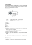
The Mountain-ICE pod contains four internal jumpers. These jumpers
are accessed by removing the four screws on the bottom of the plastic
enclosure and removing the top of the enclosure. The jumpers are
shown in figure 1. The Mountain-ICE pod also contains 2 status
LED’s. The LED on the left is for voltage status (3v/5v) and the LED
on the right is for emulator status. When the emulator is on the LED
on the right is illuminated. The LED’s are shown in figure 2.
6
Figure 1. Jumpers
Figure 2. LED’S
3.6.1 Connecting to a 5 volt target
Jumper J1 is used to differentiate between a 5 volt or 3 volt target.
This is the only jumper that most users will need to change. When the
jumper is installed the JTAG signals are configured to connect to a
5 volt target (ex. 1Blacktip™ or Snaggletooth™). When the jumper is
installed the LED on the left side is not illuminated.
3.6.2 Connecting to a 3 volt target
When the jumper is not installed the JTAG signals are configured to
connect to a 3 volt target (ex. LSI PCI/66). When the jumper is not
installed the LED on the left is illuminated. This is the default setting.
1Blacktip and Snaggletooth are trademarks of Bittware Research Systems.
7
3.6.3 Reducing noise issues on the JTAG signals
There are three jumpers provided to help reduce problems that may
arise because of ringing and reflections on the JTAG signals on the
target board. The default is that these jumpers are not installed. The
three jumpers are J2, J3, and J4.
Jumpers J2 and J3 are used for adding a parallel terminator on the
TDO and CLKIN signals. When the jumper is installed a parallel
terminator of 120Ω and 91Ω is connected to the TDO and CLKIN
signals. Figure 3 shows how the terminator is connected to the JTAG
signals. It is important to note that your target MUST be able to drive
a 51Ω load before these jumpers are installed. The DSP cannot drive
this load directly, a driver should be inserted between the JTAG
signals on the DSP and the JTAG signals on the header.
Figure 3. Terminators connected to the JTAG signals
Jumper J4 is provided to allow the board level test pins on the JTAG
connector (BTMS, BTCK, BTRST, and BTDI) to be used as ground
pins to allow for greater shielding on the JTAG cable connecting the
8
pod to the target. These pins should only be used as ground pins if
they are not used on your target.
3.7 Windows NT Driver Installation
Please refer to the emulator’s software installation guide for further
detailed instructions.
3.8 Software Installation and Operation
To install and operate the debugger software, refer to the Software
User’s Guide included with the software distribution.
3.9 Connecting the Pod to the Mountain-Ice Board
The pod connects to the Mountain-ICE board through a shielded flat
ribbon cable and a 25 pin connector. Connect the pod to the
Mountain-ICE before applying power to the PC. The JTAG header on
the opposite side of the pod can be connected/disconnected to a live (as
well as unpowered) target system without damaging the pod system.
F
Important! Connect/disconnect the remote pod
to/from the emulator card only with the power
turned off. Failure to follow this precaution may
result in damage to the pod or board.
3.10 Connecting the Pod to Your Target System
The pod connects to the target processor through the JTAG interface.
The target board must be built with an appropriate JTAG connector.
Please note the position of the key pin. The key pin should be used as
a guide to connect the pod to the target. Included with the MountainICE system are two extender connectors. These extenders are used to
connect the Mountain-ICE system to a target, which was designed for
use with the ADI ICEPAC. These extenders allow connection to the
JTAG pins on the ICEPAC header.
9
4. Support
4.1 Technical Support
We fully support all of our products. For technical support of the
Mountain-ICE, call (603) 883-2430 Monday - Friday during normal
business hours or via e-mail at [email protected]. For direct
support of the Analog Devices family of DSPs, call the Analog
Devices’ DSP Applications Engineering group at (781) 461-3672.
4.2 Quality Assurance
White Mountain DSP is committed to providing quality products and
services. In efforts to continually provide this quality, please contact
our Quality Assurance Department directly if you have any concerns at
(603) 883-2430 Monday-Friday during normal business hours or via email at [email protected]. Our Quality Assurance Manager will
listen to your concerns and provide an effective solution.
10
5. References
This section discusses other documentation resources you will need to
develop your application.
•
For information about your development platform, refer to your
operating system manuals and hardware system manuals.
•
For information about digital signal processing theory and
application, you may want to consult:
Higgins. Digital Signal Processing In VLSI. Prentice-Hall, 1990.
Oppenheim and Schafer. Digital Signal Processing. Prentice-Hall,
1975.
•
For information on the emulator software, refer to the Software
Users Guide.
•
For information on designing the interface between an Analog
Devices JTAG DSP and the emulation header on your custom DSP
target board, refer to Analog Devices JTAG Emulation Technical
Reference (2.0), EE68.
11