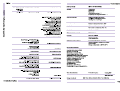
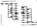
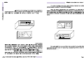
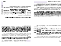
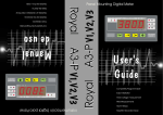
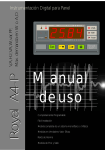
1
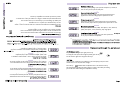
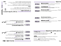
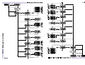
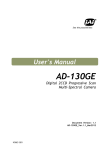
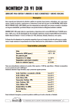
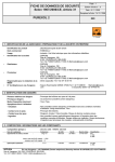
V,A,Hz,VA,W,var,PF,
Max. In W or A,D
Royal A4-P
Instrumentación Digital para Panel
V,A,Hz,VA,W,var,PF,
Royal A4-P Max.
demanda en W o A,D
Max/Min Recorded Value
Alarm Relays
RMS Measurements
Single phase or three phase complete measurement
Easy Installation
Completely Programmable
User's
Guide
Set
Royal
A4-P
4 - QUADRANTS
EXPORT
kvar
G
I
II
L
C
kW
kVA
CONTROL ALARMS
Panel Mounting Digital Meter
C
L
II
I
EXPORT
CONTROL ALARMS
kVA
kW
kvar
G
4 - QUADRANTS
Royal
A4-P
Set
Manual
de uso
Completamente Programable
Fácil Instalación
Medida completa de un sistema monofásico o trifásico
Medidas en Verdadero Valor Eficaz
Relés de Alarma
Medida de Pico y Valle
Page
Pág
Clase de precisión
Rango de frecuencia
fundamental
Rango de medida
0,5% fs
0,5% fe
40-65 Hz
40-65 Hz
0-5 A
0-500 V
Current
Tensión
0,5% fs
40-65 Hz
40-65 Hz
0-5 A
0-500 V
Corriente
0,1% fs
Voltage
(*)
(*)
Accuracy
20-500 Hz
20-500 Hz
Fundamental frequency
range
Frecuencia
(*) at 20-500 V
Frequency
Measuring range
0,5% fe
0,1% fe
(*) a 20-500 V
W
W
5
90
48
Panel Hole
92 +0,8
CAUTION!
DISCONNECT VOLTAGE
BEFORE OPENING!
133
5
45 +0,6
45 +0,6
44
44
Brida de Sujección
133
96
90
96
CAUTION!
DISCONNECT VOLTAGE
BEFORE OPENING!
92 +0,8
Dimensiones de la caja del Royal A4
Corte del Panel
Fixing Clamps
48
Dimensiones de la caja del Royal A4
N
T(L3)
T(L3)
S(L2)
S(L2)
K/P1
R(L1)
V
U
v
u
L/P2
k/S1
K/P1
R(L1)
l/S2
V
U
v
u
k/S1
L/P2
l/S2
N
T(L3)
T(L3)
S(L2)
S(L2)
R(L1)
R(L1)
Alimentación
Auxiliar
Alimentación
Auxiliar
L
NO
NC
RL2
RL2
N
NC
L
RL1
NO
NC
RL2
NO
NC
L
K/P1
v
u
k/S1
L/P2
V
l/S2
U
k/S1
K/P1
R(L1)
V
S(L2)
N
S(L2)
N
U
L/P2
l/S2
S(L2)
N
R(L1)
L
NO
N
NC
RL1
Alimentación
Auxiliar
NO
NC
RL2
NC
NC
RL2
RL1
Alimentación
Auxiliar
NO
NO
NC
RL1
N
NO
N
Alimentación
Auxiliar
L
RL2
NO
NC
L
R(L1)
R(L1)
S(L2)
S(L2)
T(L3)
T(L3)
N
R(L1)
u
v
U
V
k/S1
l/S2
K/P1
L/P2
R(L1)
S(L2)
S(L2)
T(L3)
T(L3)
N
u
v
U
V
k/S1
l/S2
K/P1
L/P2
NO
R(L1)
NC
S(L2)
N
v
RL1
R(L1)
u
NO
NC
RL1
N
NO
N
Alimentación
Auxiliar
Tabla resumen de selección de Jumpers
Jumpers position
Medida directa hasta 500V
Measurement from transformer .../110V
Medida de transformador .../110V
Direct measurement up to 500V
Situación de los Jumpers
Summary table of the selection jumpers
Synchronism at the voltage measurement
frequency
Situación de los Jumpers
Synchronism at the internal clock frequency
Sincronismo a la frec. de alimentación
Synchronism at the supply frequency
Sincronismo a la frec. de reloj interno
Jumpers position
Sincronismo a la frec. de la medida de tens.
Set
Set
Set
Set
Set
Set
Set
Set
Set
Set
Set
Set
Set
Set
Set
Set
Set
Set
Set
Set
Set
Set
Set
Set
Set
Set
Set
Set
The microprocessor will wait for the above action for a while, on the contrary the reading
process will restart without storing the modifications in memory.
Valor de la tensión que aplica en bornes del primario del transformador.
Si es >999, mediante la activación del punto decimal programamos kV.
(1)
Valor real de tensión que entrega el transformador en bornes de secundario a la entrada de tensión del instrumento. Define la relación de T.T.
Press the key
to validate all the modifications done in the instrument setup.
If no parameter is allowed to be modified, go to the last display (15CE) and check
whether this is set at YES, otherwise change it.
To modify the value of the selected digit repeatedly press the key
Set the desired 4 digits value using both above keys
To cyclically move along the four digits press the key
Valor de la corriente que desea medir a través del transformador de intensidad, cuyo secundario será por defecto de 5A. Define la relación T.I.
Sistema de fases que vamos a medir. (3Ph4): trifásico equilibrado 4
hilos, (3Ph3): Trifásico equilibrado 3 hilos, (1Ph): Monofásico
Programado en (No) impide la modificación de cualquiera de los parámetros anteriores, en (Yes) habilita la modificación.
(1)
(1)
Set at (No) it avoids any modification of the above parameters.
Set at (Yes) it enables their modification.
Para recorrer cíclicamente los cuatro digitos realizar pulsaciones sobre la tecla
Para modificar el valor de el digito seleccionado pulsar repetitivamente la tecla
Mediante ambas teclas componer el valor de 4 dígitos deseado
Phase system to be measured. (3Ph4): three phase, 4 wires, balanced;
(3Ph3): three phase, 3 wires, balanced; (1Ph): single phase
Ante la imposibilidad de modificar los parámetros ir al último nemónico (15CE), y comprobar que esta programado como (YES), si no es así modificarlo.
Value of the current to be measured through the current transformer,
whose secondary output will be by default /5A. It defines the C.T. ratio.
Para validar las modificaciones en la configuración es necesario pulsar la tecla
Set
El microprocesador esperará durante un tiempo a que realice esta acción, de lo contrario retornará a la lectura sin almacenar la modificación en memoria.
Value of the secondary voltage of the potential transformer that is
applied to the instrument voltage input. It defines the P.T. ratio.
(1)
Value of the primary voltage of the potential transformer. If >999V, kV
units are set by means of the decimal point.
Set
Set
Set
Set
Set
Set
Set
Set
Set
Set
Set
Set
Set
Set
Set
Set
Set
Set
The microprocessor will wait for the above action for a while, on the contrary the reading
process will restart without storing the modifications in memory.
Press the key
Set
to validate all the modifications done in the instrument setup.
NOTES:
If no parameter is allowed to be modified, go to the last display (24CE) and check
whether this is set at YES, otherwise change it.
Seleccionar aquí, la magnitud que desea visualizar en el display numero
uno. Ver posibles magnitudes bajo estas líneas.
Seleccionar aquí, la magnitud que desea visualizar en el display numero
dos. Ver posibles magnitudes bajo estas líneas.
Seleccionar aquí, la magnitud que desea visualizar en el display numero
tres. Ver posibles magnitudes bajo estas líneas.
Visualización de la tensión
Display of the distortion factor
Visualización de la corriente
Display of the accumulated power
Visualización de la frecuencia
Display of the power factor
Visualización de la potencia activa
Display of the apparent power
Visualización de la potencia reactiva
Display of the reactive power
Visualización de la potencia aparente
Display of the active power
Visualización del factor de potencia
Display of the frequency
Visualización de la demanda acumulada
Display of the current
Visualización del factor de distorsión
Display of the voltage
Select here the parameter to be shown on the display number 3.
See below list for available parameters.
Ante la imposibilidad de modificar los parámetros ir al último nemónico (24CE), y comprobar que esta programado como (YES), si no es así modificarlo.
Para validar las modificaciones en la configuración es necesario pulsar la tecla
Select here the parameter to be shown on the display number 2.
See below list for available parameters.
Set
El microprocesador esperará durante un tiempo a que realice esta acción, de lo contrario retornará a la lectura sin almacenar la modificación en memoria.
Select here the parameter to be shown on the display number 1.
See below list for available parameters.
Set
Set
Set
Set
Set
Set
Set
Set
Set
Set
Set
Set
Set
Set
Set
Set
Set
Set
Set
Set
Set
Set
Set
Set
Set
Set
Set
Set
Set
Set
Set
Set
Set
Set
The microprocessor will wait for the above action for a while, on the contrary the reading
process will restart without storing the modifications in memory.
Press the key
to validate all the modifications done in the instrument setup.
If no parameter is allowed to be modified, go to the last display (33CE or 42CE) and check
whether this is set at YES, otherwise change it.
To modify the value of the selected digit repeatedly press the key
Set the desired 4 digits value using both above keys
To cyclically move along the four digits press the key
Seleccionar aquí el parámetro en función del cual desea que el maxímetro realice su acumulación (Curr) corriente, o (AcPo) potencia activa..
Seleccionar aquí el tiempo de integración del maxímetro en minutos,
es decir durante cuanto tiempo desea que acumule medida.
Programado en (No) impide la modificación de cualquiera de los parámetros anteriores, en (Yes) habilita la modificación.
Seleccionar aquí, en función de que magnitud quiere leer el factor
de distorsión; en función de la tensión (Volt) o de la corriente (Curr)
Set at (No) it avoids any modification of the above parameters.
Set at (Yes) it enables their modification.
Programado en (No) impide la modificación de cualquiera de los parámetros anteriores, en (Yes) habilita la modificación.
Select here the distortion factor reference: in function of the
voltage (Volt) or in function of the current (Curr).
Set at (No) it avoids any modification of the above parameters.
Set at (Yes) it enables their modification.
Para recorrer cíclicamente los cuatro digitos realizar pulsaciones sobre la tecla
Para modificar el valor de el digito seleccionado pulsar repetitivamente la tecla
Mediante ambas teclas componer el valor de 4 dígitos deseado
Select here the integration period for the maximeter in minutes, that is,
the time period for the measurement accumulation.
Ante la imposibilidad de modificar los parámetros ir al último nemónico (33CE o 42CE), y
comprobar que esta programado como (YES), si no es así modificarlo.
Select here the parameter to be accumulated by the maximeter function:
(Curr) for the current, or (AcPo) for the active power.
Para validar las modificaciones en la configuración es necesario pulsar la tecla
Set
El microprocesador esperará durante un tiempo a que realice esta acción, de lo contrario retornará a la lectura sin almacenar la modificación en memoria.
Set
Set
Set
Set
Set
Set
Set
Set
Set
Set
Set
Set
Set
Set
Set
Set
Set
Set
Set
Set
Set
Set
Set
Set
Set
Set
Set
Set
Set
Set
Set
Set
Set
Set
Set
Set
Set
Set
The microprocessor will wait for the above action for a while, on the contrary the reading
process will restart without storing the modifications in memory.
Press the key
to validate all the modifications done in the instrument setup.
If no parameter is allowed to be modified, go to the last display (58CE) and check
whether this is set at YES, otherwise change it.
To modify the value of the selected digit repeatedly press the key
Set the desired 4 digits value using both above keys
To cyclically move along the four digits press the key
Seleccionar aquí, la magnitud a la que desea que dispare el contacto 1,
según ventana de lectura. 1, 2 ó 3.
Valor de la lectura de la anterior magnitud que desea que dispare el
contacto 1.
Especificar aquí, si quiere que el disparo se produzca al superar o al
bajar del valor de consigna programado. Al superar (HI) al bajar (LO).
Introducir la diferencia deseada entre el punto conexión de alarma y el
de desconexión en unidades del valor de magnitud elegido.
Select among two relay states. With power loss failure safety (Yes),
or without (No).
Introducir el tiempo que desea que tarde en actuar la alarma una vez
superada la consigna, en unidades de segundo. Mínimo 1 segundo.
Set at (No) it avoids any modification of the above parameters.
Set at (Yes) it enables their modification.
Especificar si deseamos que tras el disparo del contacto la alarma
quede enclavada cuando este desaparece, o por el contrario no.
Define whether the alarm relay must remain latched after a trip once the
alarm condition has already disappeared, or, on the contrary, it must not.
Elegir entre las dos modalidades de estado del contacto. Con seguridad
de fallo (Yes), y sin (No).
Fix the desired difference between the connection value of the
alarm and the disconnection one, in units of the selected parameter.
Programado en (No) impide la modificación de cualquiera de los
parámetros anteriores, en (Yes) habilita la modificación.
Delay time in seconds for the trip from the moment that the alarm
condition happened. Minimum value is 1 second.
Define here whether the trip must occur when the above alarm
condition value is exceeded (HI) or lowered (LO).
Para recorrer cíclicamente los cuatro digitos realizar pulsaciones sobre la tecla
Para modificar el valor de el digito seleccionado pulsar repetitivamente la tecla
Mediante ambas teclas componer el valor de 4 dígitos deseado
Value of the reading of the above parameter set as the alarm condition for the relay 1.
Ante la imposibilidad de modificar los parámetros ir al último nemónico (58CE), y comprobar que esta programado como (YES), si no es así modificarlo.
Select here the electrical parameter assigned to the alarm relay 1.
according to the reading window. 1, 2 or 3.
Para validar las modificaciones en la configuración es necesario pulsar la tecla
Set
El microprocesador esperará durante un tiempo a que realice esta acción, de lo contrario retornará a la lectura sin almacenar la modificación en memoria.
Set
Set
Set
Set
Set
Set
Set
Set
Set
Set
Set
Set
Set
Set
Set
Set
Set
Set
Set
Set
Set
Set
Set
Set
Set
Set
Set
Set
Set
Set
Set
Set
Set
Set
Set
Set
Set
Set
Set
Set
The microprocessor will wait for the above action for a while, on the contrary the reading
process will restart without storing the modifications in memory.
Press the key
to validate all the modifications done in the instrument setup.
If no parameter is allowed to be modified, go to the last display (68CE) and check
whether this is set at YES, otherwise change it.
To modify the value of the selected digit repeatedly press the key
Set the desired 4 digits value using both above keys
To cyclically move along the four digits press the key
Seleccionar aquí, la magnitud a la que desea que dispare el contacto 2,
según ventana de lectura. 1, 2 ó 3.
Valor de la lectura de la anterior magnitud que desea que dispare el
contacto 2.
Especificar aquí, si quiere que el disparo se produzca al superar o al
bajar del valor de consigna programado. Al superar (HI) al bajar (LO).
Introducir la diferencia deseada entre el punto conexión de alarma y el
de desconexión en unidades del valor de magnitud elegido.
Select among two relay states. With power loss failure safety (Yes),
or without (No).
Introducir el tiempo que desea que tarde en actuar la alarma una vez
superada la consigna, en unidades de segundo. Mínimo 1 segundo.
Set at (No) it avoids any modification of the above parameters.
Set at (Yes) it enables their modification.
Especificar si deseamos que tras el disparo del contacto la alarma
quede enclavada cuando este desaparece, o por el contrario no.
Define whether the alarm relay must remain latched after a trip once the
alarm condition has already disappeared, or, on the contrary, it must not.
Elegir entre las dos modalidades de estado del contacto. Con seguridad
de fallo (Yes), y sin (No).
Fix the desired difference between the connection value of the
alarm and the disconnection one, in units of the selected parameter.
Programado en (No) impide la modificación de cualquiera de los
parámetros anteriores, en (Yes) habilita la modificación.
Delay time in seconds for the trip from the moment that the alarm
condition happened. Minimum value is 1 second.
Define here whether the trip must occur when the above alarm
condition value is exceeded (HI) or lowered (LO).
Para recorrer cíclicamente los cuatro digitos realizar pulsaciones sobre la tecla
Para modificar el valor de el digito seleccionado pulsar repetitivamente la tecla
Mediante ambas teclas componer el valor de 4 dígitos deseado
Value of the reading of the above parameter set as the alarm condition for the relay 2.
Ante la imposibilidad de modificar los parámetros ir al último nemónico (28CE), y comprobar que esta programado como (YES), si no es así modificarlo.
Select here the electrical parameter assigned to the alarm relay 2.
according to the reading window. 1, 2 or 3.
Para validar las modificaciones en la configuración es necesario pulsar la tecla
Set
El microprocesador esperará durante un tiempo a que realice esta acción, de lo contrario retornará a la lectura sin almacenar la modificación en memoria.
Set
Set
Set
Set
Set
Set
Set
Set
Alarm conditions
Cond. value: 0,6 C
Trip: Low
Failure safety: No
Cond. value: 0,6 C
Trip: High
Failure safety: No
PF=1
PF=0
PF=1
PF=0
Activated relay
PF=0
PF=0
Set
Set
Rele disparado
PF=0
PF=1
Consigna: 0,45 L
Disparo: Low
Seg. de fallo: No
Cond. value: 0,45 L
Trip: High
Failure safety: No
PF=1
PF=0
PF=1
Consigna: 0,45 L
Disparo: High
Seg. de fallo: No
Activated relay
Rele disparado
PF=0
PF=1
Consigna: 0,6 C
Disparo: Low
Seg. de fallo: No
Condiciones de la alarma
Alarm conditions
Cond. value: 0,45 L
Trip: Low
Failure safety: No
PF=1
PF=0
Set
Set
PF=1
Consigna: 0,6 C
Disparo: High
Seg. de fallo: No
Condiciones de la alarma
A common application is to control the current of a motor. When it starts up, the in-rush current highly exceeds its rated
current. That peak could provoke an alarm trip that would avoid the motor startup. If a delay a little bit longer than the
duration of the motor startup process is set, this problem is solved.
Punto de disparo
programado
<10s
0
5
>10s
10 15 20 25 30 35 40 35 50 55 60 65 70 75
Activado
CONTACTO
DesactIvado
Deactivated
RELAY
Activated
0
5 10 15 20 25 30 35 40 35 50 55 60 65 70 75
<10s
>10s
Pre-set
trip point
Un uso muy frecuente es el control de la corriente de un motor. Este en su arranque produce un pico de una determinada
duración que supera el consumo normal. Este pico activaría el disparo de alarma e impediría el arranque del motor. Dando
un retardo un poco mayor que el tiempo de arranque del motor tenemos resuelto el problema.
Un claro ejemplo de aplicación lo tenemos en caso de querer permitir una intensidad máxima en una línea. Mediante el
Royal cuando sea necesario podemos desconectar equipos secundarios (aire acondicionado, ventiladores, etc...).
Supongamos que como máximo podemos consumir 200A, (esto lo conseguimos poniendo la alarma a 200) y que los
equipos secundarios tienen un consumo de 40A. Si el consumo sube a 230A el instrumento desconectará los equipos
secundarios, por lo tanto quedaremos a 190A lo que provocará otra vez la conexión subiendo a 230A y así repetitivamente.
Ahora ponemos una histéresis de 45A, al desconectar las cargas bajamos a 190A pero el punto de conexión es ahora 20045=155A con lo cual en el momento que volvamos a conectar los equipos llegaremos a 195. De esta forma aseguramos
que en la reconexión disponemos de los 40A necesarios.
Pre-set trip
point
100
DesactIvado
CONTACTO
80
Hysteresis =20
0
Activado
Activated
Alarm due to maximum
condition:
0
RELAY
The relay is not activated until the
input signal is exceeding the fixed
v a l u e . H o w e v e r, t h e r e l a y
deactivation does not occur until the
signal drops below another different
level that is given by the subtraction
of the fixed value and the set
hysteresis (for this case 100 - 20 =
80).
DeactIvated
120
Punto de disparo
programado 100
Histéresis =20
Observar como el contacto del relé no
se activa hasta que la señal de entrada
bajar del valor predetermi- nado.En
cambio, la activación no se produce
hasta que superar otro nivel de señal,
que és la suma del programado y la
histéresis seleccio- nada (en este caso
100+20=120)
COMPARACIÓN A LA
MÍNIMA
DesactIvado
CONTACTO
Pre-set trip
point
120
100
0
Activado
Activated
Histéresis =20
Alarm due to minimum
condition:
The relay is not activated until the
input signal drops below the fixed
value. However, the relay deactivation
does not occur until the signal exceeds
another different level that is given by
the addition of the fixed value and the
set hysteresis (for this case 100 + 20 =
80).
RELAY
0
Deactivated
A common application is to control the maximum current in an A.C. line. The Royal would permit to perform load shedding
actions over non-essential equipment (such as air-conditioning appliances, fans, etc.). That way, if, for instance, the
maximum allowed consumption if of 200A (the alarm condition must be set at 200A) and the consumption of the secondary
(non-essential) loads is of 40A; in case that the whole consumption rises up to 230A, the instrument will disconnect those
secondary loads, and, therefore, as the consumption will be now of 190A, those loads will be again connected reaching again
230A, and so repeatedly. Now, we set a hysteresis of 45A. When the secondary loads are disconnected, the current drops up
to 190A, but, as the present connection point is set at 200-45 = 155A, when the secondary loads are again connected the
whole current will be only of 195A. That way we assure that the secondary loads are only turned on again if their 40A of
consumption are available in the installation.
80
Punto de disparo
programado 100
Histéresis =20
Observar como el contacto del relé
no se activa hasta que la señal de
entrada supera el valor
predeterminado. En cambio, la
desactivación no se produce hasta
bajar de otro nivel de señal, que és la
resta del programado y la histéresis
seleccionada (en este caso 10020=80)
COMPARACIÓN A LA
MÁXIMA
The application appears now for conflictive installations. The signal peak can be so high as to provoke a malfunction on other
instruments connected to the line, and therefore, if the equipment that causes the peak goes on its operation, those other
instruments could be seriously damaged.
Punto de disparo
programado
0
Activado
CONTACTO
DesactIvado
Sin enclavamiento
Deactivated
RELAY
Without latch
Activated
0
Pre-set trip point
La gran utilidad aparece, al trabajar en instalaciones conflictivas. El pico de señal puede ser de un valor tan alto que
provoque avería en otros aparatos conectados. Ante la inexistencia de la función de enclavamiento, la continuación de
trabajo sin revisión de estos aparatos, les puede causar graves y costosas averías.
Función de la Seguridad de Fallo
Chapter 4
En términos de control, la seguridad de fallo és el estudio de
medidas de seguridad ante situaciones extremas. En nuestro caso
se simplifica a el mantenimineto de alarma incluso ante corte en el
suministro eléctrico.
Definitions
x
x
Alimentación
auxiliar
cortada
SIN S.F.
(no hay alarma)
CON S.F.
(si hay alarma)
La ilustración muestra los dos sistemas de operación, en el normal el
estado de reposo del relé es desactivado, por lo que para activarlo
debemos de suministrarle una excitación.
En el sistema con seguridad de fallo en cambio, el estado de reposo es
activado, y para desactivarlo debemos de suministrarle una señal.
Definiciones
No rmalme nte las alarmas s e d án p o r ac tivac ió n d e un re lé , e s d e c ir, p ara d ar alarma e xc itamo s e l re lé .
Es te s is te ma tie ne s us ve ntajas pe ro tamb ié n s us inc o nve nie nte s , y e s q ue s i e l e q uip o d e c o ntro l (R o yal)
pie rd e s u alime ntac ió n auxiliar, pie rd e tamb ié n la p o s ib ilid ad d e d ar alarma ya q ue no d is po ne mo s d e
te ns ió n para e xc itar e l re lé .
P ara lo s c as o s e n q ue ante un c o rte d e alime ntac ió n q ue ramo s alarma, d e b e mo s d e o pe rar c o n
s e g urid ad d e fallo ac tivad a. En e s te mo d o lo s re lé s func io nan al inve rs o a lo e nunc iad o . Aho ra c uand o
no hay alarma lo s re lé s e s tán e xc itad o s y e n c as o d e alarma e s tán e n re po s o (s in te ns ió n).
Capítulo 4
Page 20
Alarm ac tio n are c o mmo nly c arrie d o ut thro ug h the ac tivatio n o f a re lay, that is , the alarm trip is g o t b y
e ne rg izing the re lay. This s ys te m has s o me ad vantag e s , b ut als o s o me d is ad vantag e s , s inc e if the c o ntro l
e q uipme nt (R o yal) lo s e s its auxiliary p o w e r s upp ly, it als o lo s e s the ab ility to pe rfo rm an alarm trip s inc e
the re lay c anno t b e e ne rg ize d .
F o r tho s e s ituatio ns w hic h als o re q uire o f an alarm e ve n if a p o w e r s up ply lo s s hap pe ns , w e mus t s e le c t
the failure s afe ty o pe ratio n mo d e . That w ay, the re lays are ac tivate d w he n no alarm c o nd itio n o c c urs and
fo r an alarm s ituatio n the y w o uld b e d e ac tivate d (no vo ltag e ).
Above drawing show the two operation modes. The resting relay position
for the normal operation mode is the open (deactivated) one, which means
that the relay must be activated by energizing it.
On the contrary, for the failure safety operation mode, the resting relay
position is the closed (activated) one, and it requires for a signal to be
deactivated.
x
x
Power
supply
cut off
WITH F.S.
(Alarm on)
WITHOUT F.S.
(No alarm)
The failure safety function refers for our instrument to keep the alarm
trip even if a power supply loss failure happens.
Failure safety function
Pág. 20
100 150 200 250 300 350 400 450 500 550 600 650 700 750
SPECTRUM ANALIZER
50
100 150 200 250 300 350 400 450 500 550 600 650 700 750
50
0
0
SPECTRUM ANALIZER
0
50
100 150 200 250 300 350 400 450 500 550 600 650 700 750
SPECTRUM ANALIZER
SPECTRUM ANALIZER
0
50
100 150 200 250 300 350 400 450 500 550 600 650 700 750
S
S
I
II
CONTROL ALARMS
V/kV
A/kA
Hz
Royal
A1-P
Set
Royal
A2-P
Set
A3
A2
II
A1
CONTROL ALARMS
II
I
CONTROL ALARMS
A1
A2
A3
Royal
A2-P
Royal
A1-P
Hz
A/kA
I
II
V/kV
CONTROL ALARMS
Set
Set
I
2 alarm relays with the following options:
Trip alarm by any measure or some of these
Trip by current unbalanced
Trip by phase inversion
Trip due to maximum or minimum condition
Trip delay user-configurable between 1 and 9999s
Hysteresis user-configurable between 1 to 9999 points
Optional trip latch
Optional operation mode with failure safety function
All the set parameters can be protected against any accidental modification
I
II
CONTROL ALARMS
V1
V2
V3
Royal
A3-P
Set
Set
Royal
A5-P
A3
A2
I
A1
II
C O NTR O L A L A R MS
Measurement of three current and
unbalanced between theirs.
True RMS value measurements by
sampling.
Memorization of peak and valley values
for all the measurements.
Configuration of any .../5A current
transformer.
Royal A5
Royal A5
I
II
C O NTR O L A L A R MS
A1
A2
A3
Royal
A5-P
Set
Royal
A3-P
Set
Medida de tres intensidades y del desequilibrio entre ellas.
Medidas en verdadero valor eficaz por
muestreo y aproximaciones sucesivas.
Memorización de pico y valle en todas las
medidas.
Configurable cualquier transformador de
intensidad .../5A
2 relés de alarma con las siguientes opciones:
Disparo de alarma por una determinada medida o por cualquiera de las tres
Disparo por desequilibrio de intensidades
Disparo por inversión de fase
Disparo por máxima o mínima
Retardo de disparo programable entre 1 y 9999s.
Histeresis selecionable de 1 a 9999 puntos.
Disparos con posibilidad de latch.
Posibilidad de funcionamiento con seguridad de fallo.
Todos los parámetros configurables pueden ser protegidos contra modificación
accidental.
V3
V2
I
V1
II
CONTROL ALARMS