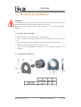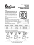
1
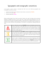
User's guide IP58, IP58S, CKP58 IQ58, IQ58S, CKQ58 Programmable incremental encoder Smart encoders & actuators This publication was produced by Lika Electronic s.r.l. 2014. All rights reserved. Tutti i diritti riservati. Alle Rechte vorbehalten. Todos los derechos reservados. Tous droits réservés. This document and information contained herein are the property of Lika Electronic s.r.l. and shall not be reproduced in whole or in part without prior written approval of Lika Electronic s.r.l. Translation, reproduction and total or partial modification (photostat copies, film and microfilm included and any other means) are forbidden without written authorisation of Lika Electronic s.r.l. The information herein is subject to change without notice and should not be construed as a commitment by Lika Electronic s.r.l. Lika Electronic s.r.l. reserves the right to make all modifications at any moments and without forewarning. This manual is periodically reviewed and revised. As required we suggest checking if a new or updated edition of this document is available at Lika Electronic s.r.l.'s website. Lika Electronic s.r.l. assumes no responsibility for any errors or omissions in this document. Critical evaluation of this manual by the user is welcomed. Your comments assist us in preparation of future documentation, in order to make it as clear and complete as possible. Please send an e-mail to the following address [email protected] for submitting your comments, suggestions and criticisms. General contents User's guide...............................................................................................................................................................................................1 General contents................................................................................................................................................................................3 Subject Index.......................................................................................................................................................................................5 Typographic and iconographic conventions..........................................................................................................................6 Preliminary information..................................................................................................................................................................7 1 Safety summary..................................................................................................................................... 8 1.1 Safety.............................................................................................................................................................................8 1.2 Electrical safety.........................................................................................................................................................8 1.3 Mechanical safety....................................................................................................................................................9 2 Identification....................................................................................................................................... 10 3 Mechanical installation..................................................................................................................... 11 3.1 Encoder with solid shaft....................................................................................................................................11 3.1.1 Customary installation................................................................................................................................11 3.1.2 Installation using fixing clamps (optional kit code LKM-386)...................................................12 3.1.3 Installation using a mounting bell (optional kit code PF4256).................................................12 3.2 Encoder with hollow shaft................................................................................................................................13 3.2.1 CKP58, CKQ58 installation using the antirotation pin..................................................................13 3.2.2 CKP59, CKQ59 installation using the fixing plate...........................................................................14 3.2.3 CKP60, CKQ60 installation using the antirotation pin and the fixing plate........................15 4 Electrical connection.......................................................................................................................... 16 4.1 Cable and connectors connections + I2C serial interface...................................................................16 4.2 T12 cable specifications......................................................................................................................................16 4.3 M23 12-pin connector specifications...........................................................................................................17 4.4 M12 12-pin connector specifications...........................................................................................................17 4.5 Connection of the shield....................................................................................................................................17 4.6 Ground connection...............................................................................................................................................18 4.7 AB0, /AB0 output channels...............................................................................................................................18 4.8 Index pulse setting input (IP-, CKP- models only)..................................................................................18 4.9 Counting direction input (IP-, CKP- models only)...................................................................................19 4.10 Diagnostic LEDs (Figure 1) (IP-, CKP- models only)..............................................................................21 4.11 Index pulse setting external button (Figure 1) (IP-, CKP- models only).......................................21 4.12 I2C (Inter Integrated Circuit) serial connection.....................................................................................23 4.12.1 Installing the KIT IP/IQ58 USB drivers................................................................................................24 5 Programming interface..................................................................................................................... 25 5.1 Configuring the encoder using the software tool...................................................................................25 5.2 Starting the program...........................................................................................................................................26 5.3 Connection with the encoder..........................................................................................................................27 5.4 Setting the parameters.......................................................................................................................................28 Internal pos. register.............................................................................................................................................................28 Resolution..................................................................................................................................................................................28 Counting direction.................................................................................................................................................................30 Index length..............................................................................................................................................................................32 Index position..........................................................................................................................................................................32 Output circuit...........................................................................................................................................................................33 Max rpm.....................................................................................................................................................................................34 Encoder status.........................................................................................................................................................................35 5.5 Diagnostics page....................................................................................................................................................36 6 Default parameters list...................................................................................................................... 37 Subject Index 1 180° el (gated A)...............................................................32 2 2250.......................................................................................34 4 4500.......................................................................................34 5 5-30V (PP/LD universal).................................................33 5V (line driver/TTL)...........................................................33 9 90° el (gated A, B)............................................................32 9000.......................................................................................34 A ADVANCED DIAGNOSTICS............................................35 B BACK TO MAIN PAGE......................................................36 C CCW........................................................................................31 CLEAR ERROR....................................................................35 Counting direction..........................................................30 CW..........................................................................................31 E ENCODER.............................................................................27 Encoder status...................................................................35 I Index length.......................................................................32 Index position....................................................................32 INTERFACE TYPE................................................................27 Internal pos. register.......................................................28 M Max rpm...............................................................................34 N NO ERROR...........................................................................35 O Output circuit....................................................................33 P PAUSE....................................................................................28 R READ......................................................................................35 Resolution...........................................................................28 S SET..........................................................................................32 START.....................................................................................28 W WARNING............................................................................35 X xxxrpm (300 kHz).............................................................34 xxxrpm (500 kHz).............................................................34 xxxrpm(100 kHz)...............................................................34 Typographic and iconographic conventions In this guide, to make it easier to understand and read the text the following typographic and iconographic conventions are used: • • • parameters and objects both of Lika device and interface are coloured in ORANGE; alarms are coloured in RED; states are coloured in FUCSIA. When scrolling through the text some icons can be found on the side of the page: they are expressly designed to highlight the parts of the text which are of great interest and significance for the user. Sometimes they are used to warn against dangers or potential sources of danger arising from the use of the device. You are advised to follow strictly the instructions given in this guide in order to guarantee the safety of the user and ensure the performance of the device. In this guide the following symbols are used: This icon, followed by the word WARNING, is meant to highlight the parts of the text where information of great significance for the user can be found: user must pay the greatest attention to them! Instructions must be followed strictly in order to guarantee the safety of the user and a correct use of the device. Failure to heed a warning or comply with instructions could lead to personal injury and/or damage to the unit or other equipment. This icon, followed by the word NOTE, is meant to highlight the parts of the text where important notes needful for a correct and reliable use of the device can be found. User must pay attention to them! Failure to comply with instructions could cause the equipment to be set wrongly: hence a faulty and improper working of the device could be the consequence. This icon is meant to highlight the parts of the text where suggestions useful for making it easier to set the device and optimize performance and reliability can be found. Sometimes this symbol is followed by the word EXAMPLE when instructions for setting parameters are accompanied by examples to clarify the explanation. Preliminary information This guide is designed to provide the most complete and exhaustive information the operator needs to correctly and safely install and operate the IP58 and IQ58 series programmable incremental encoders. IP58 / IQ58 programmable encoders from Lika Electronic are designed to maximize customization and versatility and really allow the operator to get, along with the position information, a complete parametrization and the better configuration that perfectly suit specific needs in a good many applications and machines. The operator in fact can not only configure the desired resolution or set the point in the revolution at which the 0 signal is output, but also choose for instance the voltage level of A, B and 0 output channels. IP58 / IQ58 programmable encoders are available in both solid (IP58, IP58S, IQ58, IQ58S) and hollow (CKP58, CKQ58) shaft versions. The parametrization and set up of the IP58 / IQ58 programmable encoders is achieved through a software expressly developed and released by Lika Electronic. The program is supplied for free and can be installed in any PC fitted with a Windows operating system (Windows XP or later). It allows the operator to set the working parameters of the device and monitor whether the device is running properly. The connection between the encoder and the PC is established by using the USB connection kit order code KIT IP/IQ58 provided by Lika Electronic; ZCZ connection devices need the kit to be matched with ECIP/IQ-M23 order code cordset; ZCM connection devices need the kit to be matched with EC-IP/IQ-M12 order code cordset. To make it easier to read and understand the text, this guide is divided into two main sections. In the first section some general information concerning the safety, the mechanical installation and the electrical connection as well as tips for setting up and running properly and efficiently the unit are provided. In the second section, entitled Programming Interface, both general and specific information is given on the programming interface. In this section the software tool features and the parameters implemented in the unit are fully described. IP58, IQ58 1 Safety summary 1.1 Safety • • • • • • • Always adhere to the professional safety and accident prevention regulations applicable to your country during device installation and operation; installation and maintenance operations have to be carried out by qualified personnel only, with power supply disconnected and stationary mechanical parts; device must be used only for the purpose appropriate to its design: use for purposes other than those for which it has been designed could result in serious personal and/or the environment damage; high current, voltage and moving mechanical parts can cause serious or fatal injury; warning ! Do not use in explosive or flammable areas; failure to comply with these precautions or with specific warnings elsewhere in this manual violates safety standards of design, manufacture, and intended use of the equipment; Lika Electronic s.r.l. assumes no liability for the customer's failure to comply with these requirements. 1.2 Electrical safety Turn OFF power supply before connecting the device; connect according to explanation in section ”Electrical connection”; the wires of unused output signals must be cut at different lengths and insulated singularly; • in compliance with 2004/108/EC norm on electromagnetic compatibility, following precautions must be taken: - before handling and installing the equipment, discharge electrical charge from your body and tools which may come in touch with the device; - power supply must be stabilized without noise; install EMC filters on device power supply if needed; - always use shielded cables (twisted pair cables whenever possible); - avoid cables runs longer than necessary; - avoid running the signal cable near high voltage power cables; - mount the device as far as possible from any capacitive or inductive noise source; shield the device from noise source if needed; - to guarantee a correct working of the device, avoid using strong magnets on or near by the unit; • • • MAN IP58_IQ58 E 1.2 Safety summary 8 of 40 IP58, IQ58 - minimize noise by connecting the shield and/or the connector housing and/or the frame to ground. Make sure that ground is not affected by noise. The connection point to ground can be situated both on the device side and on user’s side. The best solution to minimize the interference must be carried out by the user. 1.3 Mechanical safety • • • • • • • • Install the device following strictly the information in the section “Mechanical installation”; mechanical installation has to be carried out with stationary mechanical parts; do not disassemble the unit; do not tool the unit or its shaft; delicate electronic equipment: handle with care; do not subject the device and the shaft to knocks or shocks; respect the environmental characteristics of the product; unit with solid shaft: in order to guarantee the maximum reliability over time of the mechanical parts, we recommend a flexible coupling to be installed to connect the encoder and the installation shaft; make sure the misalignment tolerances of the flexible coupling are respected; unit with hollow shaft: the encoder can be mounted directly on a shaft whose diameter has to respect the technical characteristics specified in the purchase order and clamped by means of the collar and the fixing plate into which an anti-rotation pin has to be inserted. MAN IP58_IQ58 E 1.2 Safety summary 9 of 40 IP58, IQ58 2 Identification Device can be identified through the order code and the serial number printed on the label applied to its body. Information is listed in the delivery document too. Please always quote the order code and the serial number when reaching Lika Electronic s.r.l. for purchasing spare parts or needing assistance. For any information on the technical characteristics of the product refer to the technical catalogue. Warning: encoders having order code ending with "/Sxxx" may have mechanical and electrical characteristics different from standard and be supplied with additional documentation for special connections (Technical Info). MAN IP58_IQ58 E 1.2 Identification 10 of 40 IP58, IQ58 3 Mechanical installation WARNING Installation has to be carried out by qualified personnel only, with power supply disconnected and mechanical parts compulsorily in stop. Never force the rotation of the shaft manually, it could cause irreparable damage! 3.1 Encoder with solid shaft • Mount the flexible coupling 1 on the encoder shaft; • fix the encoder to the flange 2 (or to the mounting bell) by means of screws 3; • secure the flange 2 to the support (or the mounting bell to the motor); • mount the flexible coupling 1 on the motor shaft; • make sure the misalignment tolerances of the flexible coupling 1 are respected. 3.1.1 Customary installation IP58, IQ58 IP58S, IQ58S MAN IP58_IQ58 E 1.2 a b c d [mm] [mm] [mm] [mm] 42 50 F7 4 36 H7 48 - Mechanical installation 11 of 40 IP58, IQ58 3.1.2 Installation using fixing clamps (optional kit code LKM-386) IP58, IQ58 IP58S, IQ58S a b c d [mm] [mm] [mm] [mm] 50 F7 67 4 36 H7 67 - 3.1.3 Installation using a mounting bell (optional kit code PF4256) NOTE In order to guarantee reliability over time of the encoder mechanical parts, we recommend a flexible coupling to be installed between the encoder and the motor shaft. Make sure the misalignment tolerances of the flexible coupling are respected. MAN IP58_IQ58 E 1.2 Mechanical installation 12 of 40 IP58, IQ58 3.2 Encoder with hollow shaft 3.2.1 CKP58, CKQ58 installation using the antirotation pin • Fasten the anti-rotation pin 1 to the rear of the motor (secure it using a locknut); • mount the encoder on the motor shaft using the reducing sleeve 8 (if supplied). Avoid forcing the encoder shaft; • insert the anti-rotation pin 1 into the slot on the flange of the encoder; this secures it in place by grub screw 2, preset at Lika; • fix the collar 3 to the encoder shaft. MAN IP58_IQ58 E 1.2 Mechanical installation 13 of 40 IP58, IQ58 3.2.2 CKP59, CKQ59 installation using the fixing plate • Remove the antirotation pin 1 (see the Figure in the previous page); • mount the encoder on the motor shaft using the reducing sleeve 8 (if supplied). Avoid forcing the encoder shaft; • fasten the fixing plate 4 to the rear of the motor using two M3 cylindrical head screws 5; • fix the collar 3 to the encoder shaft. MAN IP58_IQ58 E 1.2 Mechanical installation 14 of 40 IP58, IQ58 3.2.3 CKP60, CKQ60 installation using the antirotation pin and the fixing plate • Remove the antirotation pin 1 (see the Figure on page 13); • fix the tempered pin 6 to the rear of the motor; • mount the encoder on the motor shaft using the reducing sleeve 8 (if supplied). Avoid forcing the encoder shaft; • make sure the anti-rotation pin 6 is inserted properly into the fixing plate 7; • fix the collar 3 to the encoder shaft. NOTE You are strongly advised not to carry out any mechanical operations (drilling, milling, etc.) on the encoder shaft. This could cause serious damages to the internal parts and an immediate warranty loss. Please contact our technical personnel for the complete availability of "custom made" shafts. MAN IP58_IQ58 E 1.2 Mechanical installation 15 of 40 IP58, IQ58 4 Electrical connection WARNING Electrical connection has to be carried out by qualified personnel only, with power supply disconnected and mechanical parts compulsorily in stop. Never force the rotation of the shaft manually, it could cause irreparable damage! WARNING If wires of unused signals come in contact, irreparable damage could be caused to the device. Thus they must be cut at different lengths and insulated singularly. 4.1 Cable and connectors connections + I2C serial interface Function A /A B /B 0 /0 +5VDC +30VDC 0VDC Index pulse setting * Counting direction * SDA SCL * Shield T12 cable Violet Yellow Grey Pink Green Brown Brown/Green White/Green White Blue Red Black Shield M23 12-pin 1 2 3 4 5 6 7 8 9 10 11 12 Case M12 12-pin 3 4 5 6 9 10 2 1 7 8 11 12 Case * Available only on IP-, CKP- models 4.2 T12 cable specifications Model : LIKA T12 cable Cross section : 4 x 0,25 mm2 + 4 x 2 x 0,14 mm2 twisted pairs (24/26 AWG) Jacket : TPU, extra flexible Shield : tinned copper braid, coverage > 85% Outer diameter : Ø 6.1 mm ±0.1 mm (Ø 0.24” ±0.004”) Min. bending radius : fix min. 25 mm (0.98”) / dynamic min. 45 mm (1.77”) Work temperature : fix -40 +90°C (-40° +194°F) / dyn -50 +90°C (-58° +194°F) Conductor resistance : < 90 /km (0,25 mm2) - < 148 /km (0,14 mm2) MAN IP58_IQ58 E 1.2 Electrical connection 16 of 40 IP58, IQ58 4.3 M23 12-pin connector specifications M23 12-pin connector Male Clockwise 4.4 M12 12-pin connector specifications Male Frontal side A coding 4.5 Connection of the shield For signals transmission always use shielded cables. The cable shielding must be connected properly to the metal ring nut 3 of the connector in order to ensure a good earthing through the frame of the device. To do this disentangle and shorten the shielding 1 and then bend it over the part 2; finally place the ring nut 3 of the connector. Be sure that the shielding 1 is in tight contact with the ring nut 3. MAN IP58_IQ58 E 1.2 Electrical connection 17 of 40 IP58, IQ58 4.6 Ground connection Minimize noise by connecting the shield and/or the connector housing and/or the frame to ground. Make sure that ground is not affected by noise. The connection point to ground can be situated both on the device side and on user’s side. The best solution to minimize the interference must be carried out by the user. You are advised to provide the ground connection as close as possible to the encoder. 4.7 AB0, /AB0 output channels 4.8 Index pulse setting input (IP-, CKP- models only) NOTE The Index pulse setting input is available only on IP-, CKP- models. This encoder provides the zero signal (Index pulse) once per revolution as relative positioning reference (home position, see the Figure here above). In this way a unique position can be identified at a well-known point in the 360° revolution of the encoder shaft. This input allows to set the point in the revolution at which the 0 pulse will be output. This function is useful, for example, when you want the zero position of the encoder and the zero mechanical position of the axis to match. When you want to set the position of the 0 signal in the revolution you must send a command via PLC or other controller to the encoder through the dedicated input. Connect the Index pulse MAN IP58_IQ58 E 1.2 Electrical connection 18 of 40 IP58, IQ58 setting input to 0VDC if not used. To set the zero position, connect the Index pulse setting input to +VDC for 100 µs at least, then disconnect +VDC. Normally voltage must be at 0VDC. We suggest moving the axis to the desired position, then activate the Index pulse setting function while the encoder and the mechanical assembly are in stop. WARNING Please check the position of the 0 pulse and set it if necessary whenever you set a new resolution next to the Resolution parameter or reverse the counting direction. NOTE The width of the 0 pulse can be set next to the Index length parameter. Two options are available: 90° el (gated A, B) and 180° el (gated A). Please note that the 0 pulse having a width of 90 electrical degrees is synchronised with A and B pulses, while the 0 pulse having a width of 180 electrical degrees is synchronised with A pulse. For further information please refer to page 32. NOTE It is possible to set the 0 pulse position also by either pressing the external button located in the rear side of the encoder enclosure -see the section “4.11 Index pulse setting external button (Figure 1) (IP-, CKP- models only)” on page 21 - this option is available only on IP-, CKP- models; or by means of the programming interface -see the Index position parameter on page 32 - this option is available on both IP- and IQ- series. 4.9 Counting direction input (IP-, CKP- models only) NOTE The Counting direction input is available only on IP-, CKP- models. By default the phase relationship between A and B channels is so that the rising edge of A channel leads the rising edge of B channel when the encoder is rotating in a clockwise direction (see the section “4.7 AB0, /AB0 output channels”). Thus the counter in the subsequent electronics will get a count up. This input allows to have a count up also when the encoder is rotating in a counter-clockwise direction (otherwise a count down when the encoder is rotating in a clockwise direction). Connect the Counting direction input to 0VDC if not used. Connect the Counting direction input to 0VDC to have an increasing count when the encoder is turning clockwise; connect the Counting direction MAN IP58_IQ58 E 1.2 Electrical connection 19 of 40 IP58, IQ58 input to +VDC to have an increasing count when the encoder is turning counter-clockwise. Clockwise and counter-clockwise directions are viewed from the shaft side (see the Figure on page 30). WARNING The counting direction can be set also through the programming tool. The Counting direction parameter implies that the Counting direction input is set to 0VDC. Otherwise the resulting will be contrary to what is expected or intended. The Counting direction parameter allows the operator to choose between the options CW and CCW. When the counting direction is set to CW -Counting direction = CW-, if the Counting direction input has LOW logic level (0VDC) the encoder will provide the increasing count when the shaft is turning clockwise (and the decreasing count when the shaft is turning counterclockwise); on the contrary if the Counting direction input has HIGH logic level (+VDC) the encoder will provide the increasing count when the shaft is turning counter-clockwise (and the decreasing count when the shaft is turning clockwise). When the option CCW is set -Counting direction = CCW-, if the Counting direction input has LOW logic level (0VDC) the encoder will provide the increasing count when the shaft is turning counter-clockwise (and the decreasing count when the shaft is turning clockwise); on the contrary if the Counting direction input has HIGH logic level (+VDC) the encoder will provide the increasing count when the shaft is turning clockwise (and the decreasing count when the shaft is turning counter-clockwise). WARNING After setting the new counting direction it is necessary to set also the Index pulse. MAN IP58_IQ58 E 1.2 Electrical connection 20 of 40 IP58, IQ58 4.10 Diagnostic LEDs (Figure 1) (IP-, CKP- models only) NOTE The Diagnostic LEDs are available only on IP-, CKP- models. Two LEDs located in the rear side of the encoder enclosure are intended to show visually the work status of the device as explained in the following table. GREEN LED (status) ON OFF Description The encoder is supplied and running properly The encoder is off; an error occurred in the ASIC while reading the disk RED LED (microcontroller error) Description It warns of the presence of an error: 1 SPI communication error between the microcontroller and the ASIC designed to read the disk 2 An error occurred at power on while uploading the configuration data from the EEPROM 3 An error occurred while reading the encoder position immediately after starting the encoder or after setting either the resolution or the counting direction 4 Communication error between the encoder and the PC ON 4.11 Index pulse setting external button (Figure 1) (IP-, CKP- models only) NOTE The Index pulse setting external button is available only on IP-, CKP- models. This encoder provides the zero signal (Index pulse) once per revolution as relative positioning reference (home position, see the Figure on page 18). In this MAN IP58_IQ58 E 1.2 Electrical connection 21 of 40 IP58, IQ58 way a unique position can be identified at a well-known point in the 360° revolution of the encoder shaft. The external button located in the rear side of the encoder enclosure allows to set the point in the revolution at which the 0 pulse will be output. This function is useful, for example, when you want the zero position of the encoder and the zero mechanical position of the axis to match. When you want to set the position of the 0 signal in the revolution you must move the axis to the desired position, then press the Index pulse setting button while the encoder and the mechanical assembly are in stop. Figure 1 - Diagnostic LEDs and Index pulse setting button WARNING Please do not press the Index pulse setting external button when the encoder configuration interface program is running. WARNING Please check the position of the 0 pulse and set it if necessary whenever you set a new resolution next to the Resolution parameter or reverse the counting direction. NOTE The width of the 0 pulse can be set next to the Index length parameter. Two options are available: 90° el (gated A, B) and 180° el (gated A). Please note that the 0 pulse having a width of 90 electrical degrees is synchronised with A and B pulses, while the 0 pulse having a width of 180 electrical degrees is synchronised with A pulse. For further information please refer to page 32. MAN IP58_IQ58 E 1.2 Electrical connection 22 of 40 IP58, IQ58 NOTE It is possible to set the 0 pulse position also by either sending a signal via PLC or other controller through the dedicated input -see the section “4.8 Index pulse setting input (IP-, CKP- models only)” on page 18- option available only on IP-, CKP- models; or by means of the programming interface -see the Index position parameter on page 32- option available on both IP- and IQ- series. 4.12 I2C (Inter Integrated Circuit) serial connection The IP58/IQ58 programmable encoder is equipped with a serial interface for the parametrization and set-up of the device. The serial interface is a I2C (Inter Integrated Circuit) type interface. To communicate with the encoder, you must connect the device to the personal computer through a USB socket using the specific connection kit supplied by Lika Electronic upon request. The connection kit code is KIT IP/IQ58. It is provided with a terminal for connecting the cable of the devices having ZCU output circuit code. ZCZ connection devices need the kit to be matched with a cable - M23 12-pin female connector cordset, EC-IP/IQ-M23 order code; ZCM connection devices need the kit to be matched with a cable - M12 12-pin female connector cordset, EC-IP/IQ-M12 order code. To connect the encoder to the connection kit, please refer to the following table and the label applied to the connection kit terminal: Function Encoder/cordset cable Terminal +5VDC power supply * Brown/Green PWR+ 0VDC White/Green PWR- SDA Serial Data Line Red SDA SCL Serial Clock Line Black SCL * WARNING +5VDC power supply from the USB connection. Do not connect any external power supply sources. WARNING Please make sure that only one encoder is connected to the KIT IP/IQ58 when you activate the USB connection ! MAN IP58_IQ58 E 1.2 Electrical connection 23 of 40 IP58, IQ58 NOTE Before configuring the encoder by means of the programming interface, you must connect it to the personal computer through the KIT IP/IQ58 connection cable. You are required to install the drivers of the USB Serial Converter and the USB Serial Port first. The drivers are available for download at the address http://www.lika.it/eng/prodotti.php?id_cat=267&id_fam=271&filtro=170 . 4.12.1 Installing the KIT IP/IQ58 USB drivers Please follow the steps in the documents listed below to install the drivers of both the USB Serial Converter and the USB Serial Port of the KIT IP/IQ58. The drivers package and the relevant documents are found inside the DRIVER USB folder. As stated, the drivers are available for download at the following address http://www.lika.it/eng/prodotti.php?id_cat=267&id_fam=271&filtro=170 . If you need to install the drivers under the Microsoft Windows XP operating system, please refer to the following document: Installation_Guide_for_WindowsXP.pdf. If you need to install the drivers under the Microsoft Windows Vista operating system, please refer to the following document: Installation_Guide_for_VISTA.pdf. If you need to install the drivers under the Microsoft Windows 7 or 8 operating system, please refer to the following document: Installation_Guide_for_Windows7.pdf. As a preliminary operation please: 1. connect the encoder to the KIT IP/IQ58 terminal through the encoder cable or using either the M23 12-pin connector cordset or the M12 12pin connector cordset (for the cable connection scheme please refer to the table in the previous page); you do not need to power the encoder by means of an external power pack as the device gets the power from USB; 2. connect the cable fitted with the USB connector to a USB socket of your PC; after a few seconds a message will appear in the notification area of the Windows taskbar and the USB Serial Converter drivers installation wizard will start. Then follow the instructions in the above mentioned pdf documents. After installation you can launch the executable file and open the encoder programming interface; to know more refer to the section “Programming interface” on page 25. MAN IP58_IQ58 E 1.2 Electrical connection 24 of 40 IP58, IQ58 5 Programming interface 5.1 Configuring the encoder using the software tool IP58/IQ58 programmable incremental encoder is supplied with a software expressly developed and released by Lika Electronic in order to easily programme and configure the device. It allows the operator to set the working parameters of the device and monitor whether the device is running properly. The program is supplied for free and can be installed in any PC fitted with a Windows operating system (Windows XP or later). The name of the program executable file is KIT_IP_IQ58_vx.x.exe where vx.x is the release version of the file. The program is available for download at the following address http://www.lika.it/eng/prodotti.php?id_cat=267&id_fam=271&filtro=170 . The program is designed to be installed simply by copying the executable file (*.exe file) to the desired location and there is no installation process. To launch the program just double-click the file icon. To close the program press the EXIT button in the title bar. WARNING "libMPSSE.dll" file must be located in the same directory as the executable file! WARNING Please be aware that the following compatibilities between the hardwaresoftware version of the device and the software version of the executable file have to be respected compulsorily. Compatibility HW-SW Connection kit EXE FILE IP58 1-1 KIT IP58 R1, R1_1 IP58, IQ58 1-1 KIT IP58, KIT IP/IQ58 From v2.0 up to … The new programming interface (from v2.0 release on) allows the connection to both the IP58 series and the IQ58 series using either the KIT IP58 (if you already have one) or the KIT IP/IQ58. The old programming interface (R1, R1_1 releases) allows the connection to the IP58 series only, using the KIT IP58. In all cases you must comply with the hardware and software compatibility indicated in the table. NOTE Before starting the program and establishing a communication with the device, it is necessary to connect it to the personal computer. The interface is a I 2C MAN IP58_IQ58 E 1.2 Programming interface 25 of 40 IP58, IQ58 (Inter Integrated Circuit) serial interface. To communicate with the encoder, you must connect the device to the personal computer through a USB port using the specific connection kit order code KIT IP/IQ58 supplied by Lika Electronic. For any further information please refer to the section “4.12 I2C (Inter Integrated Circuit) serial connection” on page 23. WARNING Please make sure that only one encoder is connected to the KIT IP/IQ58 when you activate the USB connection ! WARNING Please always close the programming interface before disconnecting the encoder ! 5.2 Starting the program To launch the program just double-click the KIT IP_IQ58_vx.x.EXE executable file. The main page of the configuration interface will appear on the screen. A further page is dedicated to the diagnostic information; it can be accessed by pressing the ADVANCED DIAGNOSTICS button below in the page (see on page 36). First of all the main page allows the operator to choose the language used to display texts and items in the user interface. Click the Italian flag icon to choose the Italian language; click the UK flag icon to choose the English language. Two sections can be found in the main page of the configuration interface: 1. a top section groups the items needful to establish the connection between the encoder and the interface, the connection buttons as well as the drop-down boxes designed to select the interface type and the series of the encoder to connect; 2. the section where the parameters to program the encoder can be found; also the buttons to check the work status of the encoder and enter the diagnostic information page can be found below in this section. MAN IP58_IQ58 E 1.2 Programming interface 26 of 40 IP58, IQ58 5.3 Connection with the encoder When you start the program, the system automatically recognizes the type of interface you plugged into (INTERFACE TYPE: “KIT IP58” or “KIT IP/IQ58”). You are required to select the series of the encoder you need to connect to instead. To do this open the ENCODER drop-down box and select from the options in the list: “IP58, IP58S, CKP58” or “IQ58, IQ58S, CKQ58”. The encoder model can be found in the label applied to the device enclosure. If the connection is established properly, a green tick appears next to both buttons; on the contrary, if the program is not able to establish a connection to the encoder, a red X appears next to either button. After positive connection the fields in the page are filled with information acquired from MAN IP58_IQ58 E 1.2 Programming interface 27 of 40 IP58, IQ58 the connected device. Furthermore the buttons and the commands become active. 5.4 Setting the parameters WARNING To save the data on the EEPROM permanently, after having entered the new value you must press the ENTER button in the keyboard. The parameter is saved instantly. Internal pos. register It is used to show the value in the internal position register, that is: the current position of the encoder. When you start the program, 0 appears next to this item. Press the START button to start the routine which allows to continuously read and display the current position: the encoder current position appears on the field. Press the PAUSE button to stop the routine; the last position value is kept “frozen” in the display field. After having set a new resolution value, a zero setting operation is carried out by the system. If the routine is running, the 0 value is shown in the internal position register; otherwise the last “frozen” position is shown. Resolution This parameter allows the operator to set a custom number of pulses the encoder will output per each revolution (PPR). Please enter the desired value and then press the ENTER button to confirm. If you set a value that is out of range (lower or greater than allowed), the system automatically sets either the minimum or the maximum value in the range. After having set the resolution, set also the encoder maximum rotational speed, see the parameter Max rpm. Please always consider the pulse multiplication factor (x 1, x 2 or x 4) of your subsequent electronics before entering a new resolution value. Default = 1024 (min. value = 1; max. value = 65536) - IP58 series Default = 1024 (min. value = 1; max. value = 16384) - IQ58 series EXAMPLES Here are some examples useful to better understand the application field of the programmable resolution. We assume that the pulse multiplication factor in the following electronics is x 1. MAN IP58_IQ58 E 1.2 Programming interface 28 of 40 IP58, IQ58 Example 1 Let's assume that the encoder is mounted on the driven draw roller of a slitter and the circumference of the roller is 753 mm. We can set a resolution of 7530 PPR (Resolution = 7530) to control the movement of the roller with a tenth of a millimetre resolution. In this way we convert a rotary measurement value (for example: 10000 PPR) into a linear measurement value, thus we are able to control the unwinding of a plastic or paper web from the reel and activate the blades to cut 1-m long sheets with a tenth of a millimetre resolution. Example 2 Let's assume that an axis is guided by a ball screw; a motor fitted with a reduction gearbox having 1:50 reduction ratio is installed at an end of the system, while the encoder is installed at the opposite end of the system. MAN IP58_IQ58 E 1.2 Programming interface 29 of 40 IP58, IQ58 As we know the reduction ratio of the reduction gearbox, we can set a suitable resolution in order to control the motion of the motor precisely and calculate the input speed starting from the known output speed. Example 3 Let's assume that the encoder is mounted on the SFI draw wire unit and the application has a 5500-mm long linear travel. We can set a resolution of 55000 PPR (Resolution = 55000) to control the movement of the cable and thus of the axis with a tenth of a millimetre resolution. In this way we convert a rotary measurement value (55000 PPR) into a linear measurement value, therefore we are able to control the 5.5-m long linear travel with a tenth of a millimetre resolution. Example 4 Let's assume that the encoder is used to control the movement of a chain conveyor. The chain conveyor is equipped with multiple stations and has an overall length of 14.847 m. If we set a resolution of 14847 PPR (Resolution = 14847) we have precise control over the movement of the chain conveyor and its positioning at the stations with a millimetre resolution. Counting direction By default the phase relationship between A and B channels is so that the rising edge of A channel leads the rising edge of B channel when the encoder is rotating in a clockwise direction (see the Figure on page 32). Thus the counter in the subsequent electronics will get a count up. This parameter allows to have a count up also when the encoder is rotating in a MAN IP58_IQ58 E 1.2 Programming interface 30 of 40 IP58, IQ58 counter-clockwise direction (otherwise a count down when the encoder is rotating in a clockwise direction). Set Counting direction = CW to have the increasing count when the shaft is turning clockwise; set Counting direction = CCW to have the increasing count when the shaft is turning counter-clockwise. Clockwise and counter-clockwise directions are viewed from the shaft side (see the Figure in the previous page). Default = CW (min. value = CCW; max. value = CW) WARNING The counting direction can be set both via hardware (see the Counting direction input, section “4.9 Counting direction input (IP-, CKP- models only)” on page 19 - this option is available only on IP-, CKP- models) and via software by programming the Counting direction parameter. If not used, the Counting direction input must be connected to 0VDC. The Counting direction parameter implies that the Counting direction input is set to 0VDC. Otherwise the resulting will be contrary to what is expected or intended. The Counting direction parameter allows the operator two choose between the options CW and CCW. When the counting direction is set to CW -Counting direction = CW-, if the Counting direction input has LOW logic level (0VDC) the encoder will provide the increasing count when the shaft is turning clockwise (and the decreasing count when the shaft is turning counter-clockwise); on the contrary if the Counting direction input has HIGH logic level (+VDC) the encoder will provide the increasing count when the shaft is turning counter-clockwise (and the decreasing count when the shaft is turning clockwise). When the option CCW is set -Counting direction = CCW-, if the Counting direction input has LOW logic level (0VDC) the encoder will provide the increasing count when the shaft is turning counter-clockwise (and the decreasing count when the shaft is turning clockwise); on the contrary if the Counting direction input has HIGH logic level (+VDC) the encoder will provide the increasing count when the shaft is turning clockwise (and the decreasing count when the shaft is turning counterclockwise). For any information on the electrical connection of the Counting direction input refer to the sections “Electrical connection“ on page 16 and “4.9 Counting direction input (IP-, CKP- models only)“ on page 19. WARNING After having set the new counting direction it is necessary to set also the Index pulse. MAN IP58_IQ58 E 1.2 Programming interface 31 of 40 IP58, IQ58 Index length This parameter allows to set the width of the Index pulse (0 pulse) expressed in electrical degrees. Two options are available and selectable in the drop-down box: 90° el (gated A, B) and 180° el (gated A). Please note that the 0 pulse having a width of 90 electrical degrees is synchronised with A and B pulses, while the 0 pulse having a width of 180 electrical degrees is synchronised with A pulse. See the Figure below. Default = 90° el (gated A, B) Min. value = 90° el (gated A, B); max. value = 180° el (gated A) Index position This encoder provides the zero signal (Index pulse) once per revolution as relative positioning reference (home position, see the Figure above). In this way a unique position can be identified at a well-known point in the 360° revolution of the encoder shaft. This function allows to set the point in the revolution at which the 0 pulse will be output. It is useful, for example, when you want the zero position of the encoder and the zero mechanical position of the axis to match. When you want to set the position of the 0 signal in the revolution you must move the axis to the desired position, then press the SET button next to this Index position item while the encoder and the mechanical assembly are in stop. MAN IP58_IQ58 E 1.2 Programming interface 32 of 40 IP58, IQ58 WARNING Please check the position of the 0 pulse and set it if necessary whenever you set a new resolution next to the Resolution parameter or reverse the counting direction. NOTE The width of the 0 pulse can be set next to the Index length parameter. Two options are available: 90° and 180°. Please note that the 0 pulse having a width of 90 electrical degrees is synchronised with A and B pulses, while the 0 pulse having a width of 180 electrical degrees is synchronised with A pulse. For further information please refer to page 32. NOTE It is possible to set the 0 pulse position also by either sending a signal via PLC or other controller through the dedicated input -see the section “4.8 Index pulse setting input (IP-, CKP- models only)” on page 18-; or by pressing the external button located in the rear side of the encoder enclosure -see the section “4.11 Index pulse setting external button (Figure 1) (IP-, CKP- models only)” on page 21. Both these options are available only on IP-, CKP- models. Output circuit NOTE This parameter is available only on IP-, CKP- models. This parameter allows to set the voltage level of AB0, /AB0 output channels. You can choose between 5V and the encoder power supply voltage level (+VDC). In the drop-down box select the 5V (line driver/TTL) option to have a voltage level of 5V at output channels; select the 5-30V (PP/LD universal) option to have a voltage level at output channels according to the encoder power supply voltage level (5V to 30V). Default = 5-30V (PP/LD universal) Min. value = 5V (Line driver/TTL); max. value = 5-30V (PP/LD universal) EXAMPLE Let's assume that the encoder power supply voltage level is 12V; in this case you can have the output channels at either 5V voltage level -by setting the 5V (Line driver/TTL) option- or 12V -by setting the 5-30V (PP/LD universal) option-. MAN IP58_IQ58 E 1.2 Programming interface 33 of 40 IP58, IQ58 Max rpm It allows to optimize the encoder performance (by keeping the most efficient ratio between either the rotational speed and the precision in the case of the IP58 encoder; or the rotational speed and the edge distance in the case of the IQ58 encoder), depending on the maximum speed the application is able to reach. Since the maximum speed and the resolution are strictly correlated, some options may be disabled or limited as you enter increasing resolutions. If more options are available -2250; 4500; 9000 for IP58 encoder; xxxrpm(100 kHz); xxxrpm (300 kHz); xxxrpm (500 kHz) for IQ58 encoder-, the operator has to select the speed value option that is immediately higher than the maximum speed of the application. If you do not know the maximum speed the application is able to reach, please enter the maximum rotational speed option available. EXAMPLE Let's assume the resolution of an IP58 encoder to be 1024 PPR; in this case three options are available for you to choose from: 2250, 4500 and 9000 rpm. If the maximum speed of the application is 4000 rpm, you have to select the 4500 rpm option; if the maximum speed of the application is 4500 rpm, you have to select the 9000 rpm option; if you do not know the maximum speed of the application, you have to select the 9000 rpm option. NOTE Please note that the maximum counting frequency of an encoder, expressed in kHz, results from the number of revolutions per minute (RPM) -i.e. its rotational speed- and the number of pulses per revolution (PPR) -i.e. its resolution. It can be calculated by using the following algorithm: Maximum counting frequency (kHz) = RPM * PPR 60 * 1000 It follows that the higher the maximum rotational speed of the encoder and its resolution, the higher the counting frequency. This has to be considered carefully when you program the encoder, in particular referring to the maximum counting frequency of the encoder as stated in the technical specifications, to the following electronic equipment and to the length of the cables. If you reverse the formula you can easily calculate the maximum number of revolutions starting from the value of the counting frequency (as allowed by the encoder, permitted by the subsequent electronics and accepted by the cable run) and the desired number of pulses per revolution: MAN IP58_IQ58 E 1.2 Programming interface 34 of 40 IP58, IQ58 RPM = Maximum counting frequency (kHz) * 60 * 1000 PPR The reversed formula can be very useful -for instance- when you know the maximum counting frequency that is applicable to the system (because of the encoder, the following electronics and the cable length) and you need to calculate the maximum rotational speed the encoder is allowed to reach at the desired resolution. Encoder status It displays the work status of the encoder. Press the READ button to update the status visualization. If the encoder is working properly, the NO ERROR message appears on the right of the READ button. If a fault condition arises, the WARNING message is invoked to appear. By pressing the CLEAR ERROR button the system tries to solve the problem. If this is not possible, please press the ADVANCED DIAGNOSTICS button to learn more about the occurred fault. MAN IP58_IQ58 E 1.2 Programming interface 35 of 40 IP58, IQ58 5.5 Diagnostics page When you press the ADVANCED DIAGNOSTICS button in the main page, you enter the Diagnostics page. In this page you can find detailed information on the work status of the encoder. The current status is described in the window in the bottom right. If an error occurs the system is not able to solve by pressing the CLEAR ERROR button, please take note of the error code that appears in the window and reach Lika Electronic's After Sales and Technical Service. Press the BACK TO MAIN PAGE button to display back the main page. MAN IP58_IQ58 E 1.2 Programming interface 36 of 40 IP58, IQ58 6 Default parameters list Parameters list Resolution Counting direction Index length Index position Output circuit Max rpm Default value 1024 * CW 90° el (gated A, B) 0 5-30V (PP/LD universal) 9000 * 1024 PPR is the default resolution of the PROG order code version only, for instance: IP58-H-PROGZCU48RL2. Versions with factory preset resolution may provide different PPR information, see your specific order code in the label applied to the encoder enclosure, for instance: CKP58-H-1000ZCM415RL2 (in this case: preset resolution = 1000 PPR). MAN IP58_IQ58 E 1.2 Default parameters list 37 of 40 This page intentionally left blank This page intentionally left blank HW-SW version Interface release Document release Description 1-1.0 1.0 1.0 1st issue 1-1.0 1.1 1.1 Interface update Added new IQ- series, new 1-1.0 2.0 1.2 programming interface This device is to be supplied by a Class 2 Circuit or Low-Voltage Limited Energy or Energy Source not exceeding 30 VDC. Refer to the ordering code for supply voltage rate. Please check the supply voltage specification in the product datasheet. Dispose separately LIKA Electronic Via S. Lorenzo, 25 36010 Carré (VI) • Italy Tel. +39 0445 806600 Fax +39 0445 806699 Italy: eMail [email protected] - www.lika.it World: eMail [email protected] - www.lika.biz