1
Instruction Set
Instruction Set
PicoBlaze Instruction Set
PicoBlaze Instruction Set
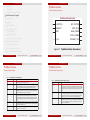
JUMP
CALL
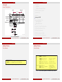
The CALL instruction is similar in operation to the JUMP instruction in that it will modify the normal program execution sequence by
specifying a new address. The CALL instruction may also be conditional. In addition to supplying a new address, the CALL
instruction also causes the current program counter (PC) value to be pushed onto the program counter stack. The CALL instruction
has no effect on the status of the flags.
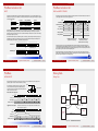
Under normal conditions, the program counter (PC) increments to point to the next instruction. The address space is fixed to
1024 locations (000 to 3FF hex) and therefore the program counter is 10 bits wide. It is worth noting that the top of memory is
3FF hex and will increment to 000.
PC
PC
+1
Unconditional or
condition valid
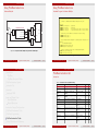
The JUMP instruction may be used to modify this sequence by specifying a new address. However, the JUMP instruction may be
conditional. A conditional JUMP will only be performed if a test performed on either the ZERO flag or CARRY flag is valid. The
JUMP instruction has no effect on the status of the flags.
Condition
not valid
JUMP
JUMP
JUMP
JUMP
JUMP
14
13
0
1
0
Bit 12
12
11
10
9
8
7
6
5
4
3
2
1
0
a
a
a
a
a
a
a
a
a
a
0 - UNCONDITIONAL
1 - CONDITIONAL
J
c Dr inż. Ignacy Pardyka (Inf ∈ UK
)
0
0
1
1
0
1
0
1
programowanie struktur cyfrowych
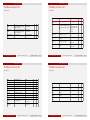
Each CALL instruction must specify the 10-bit address as a 3 digit hexadecimal value. The assembler supports labels to simplify
this process.
Bit 11 Bit 10
Condition
17
if Zero
if NOT Zero
if Carry
if NOT Carry
Rok akad. 2011/2012
16
15
14
13
1 1
0
0
0
Bit 12
13 / 96
12
11
10
9
8
7
6
5
4
3
2
1
0
a
a
a
a
a
a
a
a
a
a
J
c Dr inż. Ignacy Pardyka (Inf ∈ UK
)
PicoBlaze Instruction Set
RETURNI
Stack
+1
PC
Stack
RETURN
RETURN
RETURN
RETURN
RETURN
+1
Unconditional or
condition valid
13
0
1
Bit 12
12
11
10
9
8
7
6
5
4
3
2
1
0
0
0
0
0
0
0
0
0
0
0
0 - UNCONDITIONAL
1 - CONDITIONAL
J
c Dr inż. Ignacy Pardyka (Inf ∈ UK
)
programowanie struktur cyfrowych
Preserved
CARRY
ZERO
Preserved
ZERO
INTERRUPT
ENABLED
Z
NZ
C
NC
Bit 11
Bit 10
0
0
1
1
0
1
0
1
ENABLE
DISABLE
14 / 96
‘1’
‘0’
It is the responsibility of the programmer to ensure that a RETURNI is only performed in response to an interrupt. Each RETURNI
must specify if further interrupt is to be enabled or disabled.
RETURNI ENABLE
14
CARRY
PC
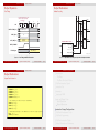
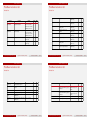
It is the responsibility of the programmer to ensure that a RETURN is only performed in response to a previous CALL instruction
such that the program counter stack contains a valid address. The cyclic implementation of the stack will continue to provide
values for RETURN instructions which can not be defined.
1
Rok akad. 2011/2012
The RETURNI instruction is a special variation of the RETURN instruction which should be used to conclude an interrupt service
routine. The RETURNI is unconditional and therefore will always load the program counter (PC) with the last address on the
program counter stack (the address is not incremented in this case since the instruction at the address stored will need to be
executed). The RETURNI instruction restores the flags to the condition they were in at the point of interrupt. The RETURNI also
determines the future ability of interrupts using ENABLE and DISABLE as an operand.
The RETURN instruction is the complement to the CALL instruction. The RETURN instruction may also be conditional. In this case
the new program counter (PC) value will be formed internally by incrementing the last value on the program address stack. This
ensures that the program will execute the instruction following the CALL instruction which resulted in the subroutine. The RETURN
instruction has no effect on the status of the flags.
Condition
PC
not valid
15
if Zero
if NOT Zero
if Carry
if NOT Carry
Instruction Set
RETURN
16
0
1
0
1
programowanie struktur cyfrowych
PicoBlaze Instruction Set
1 0
0
0
1
1
0 - UNCONDITIONAL
1 - CONDITIONAL
Instruction Set
17
aaa
Z,aaa
NZ,aaa
C,aaa
NC,aaa
The program counter stack supports a depth of 31 address values. This enables nested ‘CALL’ sequences to a depth of 31 levels
to be performed. However, the stack will also be used during an interrupt operation and hence at least one of these levels should
be reserved when interrupts are enabled. The stack is implemented as a separate cyclic buffer. When the stack becomes full, it
simply overwrites the oldest value. Hence it is not necessary to reset the stack pointer when performing a software reset. This also
explains why there are no instructions to control the stack and why no other memory needs to be reserved or provided for the
stack.
aaa
Z,aaa
NZ,aaa
C,aaa
NC,aaa
Each JUMP instruction must specify the 10-bit address as a 3 digit hexadecimal value. The assembler supports labels to simplify
this process.
Bit 11 Bit 10
Condition
15
CALL
CALL
CALL
CALL
CALL
New Address
a a a a a a a a a a
Unconditional or
condition valid
Unconditional or
condition valid
16
+1
+1
New Address
a a a a a a a a a a
1 1
PC
PC
PC
PC
17
Condition
not valid
Stack
Normal Instruction
17
16
15
14
13
1
1
1
0
0
17
16
15
14
13
1
1
1
0
0
12
11
10
9
8
7
6
5
4
3
2
1
0
0 0
0
0
0
0
0
0
0
0
0
0
1
Condition
if Zero
if NOT Zero
if Carry
if NOT Carry
Rok akad. 2011/2012
RETURNI DISABLE
15 / 96
J
c Dr inż. Ignacy Pardyka (Inf ∈ UK
)
12
11
10
9
8
7
6
5
4
3
2
1
0
0 0
0
0
0
0
0
0
0
0
0
0
0
programowanie struktur cyfrowych
Rok akad. 2011/2012
16 / 96