1
PC3000
USER GUIDE
Book 2
Languages
© Copyright Eurotherm Controls Limited 1993
All rights strictly reserved. No part of this document may be stored in a retrieval system, or any form or
by any means without prior written permission from Eurotherm Controls Limited.
Every effort has been taken to ensure the accuracy of this specification. However in order to maintain
our technological lead we are continuously improving our products which could, without notice, result
in amendments or omissions to this specification. We cannot accept responsibility for damage, injury
loss or expenses resulting therefrom.
HA022932 Iss 3.1
CONTENTS
Chapter
1 ....... INTRODUCTION
Chapter
2 ....... PROGRAMMING CONCEPTS
Chapter
3 ....... STRUCTURED TEXT
Chapter
4 ....... SEQUENTIAL FUNCTION CHARTS
Chapter
5 ....... PROGRAM DEVELOPMENT
Index
PC3000 User Guide
Contents
Chapter 1
INTRODUCTION
Edition 1
Contents
OVERVIEW .................................................................... 1-1
PC3000 USER GUIDES .................................................. 1-1
Book 1 - PC3000 programming ............................... 1-1
Book 2 - PC3000 language ...................................... 1-1
Book 3 - PC3000 in application ................................ 1-2
PC3000 REFERENCES .................................................... 1-2
PC3000 real time operating system reference ............ 1-2
PC3000 hardware reference ..................................... 1-2
PC3000 functions reference ...................................... 1-2
PC3000 function block reference............................... 1-3
ABOUT THIS GUIDE ...................................................... 1-3
TERMINOLOGY AND ABBREVIATIONS ........................... 1-4
PC3000 User Guide HA022932 Iss 3
Cont. i
Introduction
OVERVIEW
PC3000 is the first of a new generation of programmable process controllers
which can be used to control both production and prototype processes. To develop
control programs for the PC3000, Eurotherm Controls provide two advanced
programming stations: the DOS based Programming Station which is fully
described in this User Guide and the Microcell Programming Station which
provides full graphical and spreadsheet programming along with integrated mimic
screens and recipe management.
Both Programming Stations offer a full repetoire of facilities accessed by menus
and user friendly screens.
These both provide the control and system engineer with a work station that is
specifically designed to ease the task of developing control programs - through all
phases from initial concept, development, commissioning to on-line operation.
Each system also provides built-in help information so that descriptions of many
functions and editors can be accessed directly from the screen.
In order to allow you to fully exploit the rich functionality of PC3000, further
information is also provided by a suite of user guides and reference manuals.
PC3000 USER GUIDES
To help you use the PC3000 Programming Station, the user guides are arranged as
a set of four books. Each book contains one or more manuals and is structured to
answer specific basic questions :
Book 1 - PC3000 programming
"How do you use PC3000 ?"
Book 1 will tell you how to use all the facilities of the programming station to
develop and commission your control programs.
Book 2 - PC3000 languages
"What facilities does PC3000 provide ?"
This user guide introduces the programming languages and concepts used by
PC3000. It also provides some simple examples of the languages.
PC3000 User Guide
1-1
Introduction
Book 3 - PC3000 in application
"Why are certain facilities provided and how can they be used ?"
This book contains a number of overviews on specific topics including :
PC3000 Communications overview
- introduces facilities and special function blocks which enable PC3000 to
exchange control information and real-time data with other PC3000s and other
proprietary equipment such as Programmable Controllers, SCADA, and
Supervisory systems .
PC3000 Control overview
- describes some of the standard methods and techniques used for the control of
processes using the PC3000 built-in and user-programmable function blocks,
specically those concerned with PID.
PC3000 REFERENCES
In addition to the user guides, a number of reference manuals are provided to give
detailed information on a wide range of topics. These manuals are not intended to
be read cover-to-cover but are structured so that specific information can be
located quickly.
The PC3000 Reference manuals include :
PC3000 real time operating system reference:
- provides a detailed description of the PC3000 real-time system and related topics
including multi-tasking, performance, memory lay-out and fault detection.
PC3000 hardware reference
- provides detailed information on all the PC3000 hardware modules including
calibration, wiring and physical configuration details.
PC3000 functions reference
- describes all the functions that can be called within the Structured Text (ST)
language.
1-2
PC3000 User Guide
Introduction
PC3000 function block reference
- describes the numerous function blocks available to be incorporated into your
control program for PID control, Ramps, Counters, Filters, Timers etc.
Note: as it is the policy of Eurotherm Controls to continually refine
and provide additional product information, the list and description
of manuals provided for your system may differ slightly from those
described.
ABOUT THIS GUIDE
You are advised read this guide before developing a PC3000 control program.
PC3000 performance can be optimised and the integrity of the program ensured if
a few simple principles are followed. This guide is written to supplement the
PC3000 User Guide Book 1 Programmimg. It is envisaged that you may need to
reference both user guides when developing programs for the first time.
Chapter 2 provides an overview of the PC3000 languages and concepts and is
useful if you wish to quickly understand how the PC3000 can be programmed to
solve control problems. A simple program example is described that depicts many
of these concepts.
Chapter 3 provides a detailed description of the Structured Text language with
examples.
Chapter 4 describes how to use the PC3000 Sequential Function Charts to
program all the sequencing needs of both simple and complex control systems.
Chapter 5 is particularly important . You are advised to read Chapter 5 sections:
Program Design Considerations and Program Development Stages, before starting
a major programming project.
PC3000 User Guide
1-3
Introduction
TERMINOLOGY AND ABBREVIATIONS
The following abbreviations are used in this user guide :
Actions
The Structured Text statements, including assignments
that are evaluated when a specific step is active.
Assignment
A Structured Text statement that produces a value that
is written to a specified function block parameter.
Boolean Expression
A Structured Text expression that produces a "true" or
"false" result.
Chart
A Sequential Function Chart is a collection of
graphically connected (wired) steps and transitions that
form one or more sequences. It always has a single
start step.
Expression
A Structured Text construct that produces a value of a
specific data type.
Function Block Instance
A Function Block that has been created to be of a
particular Function Block type and has a unique name.
Instantiation
The process of creating Function Blocks of a particular
function block type.
PID
Proportional, Integral and Derivative control algorithm
SFC
Refers to the IEC Sequential Function Charts language
and construction.
ST
Refers to the IEC Structured Text high level language
Statement
A Structured Text language statement is a collection of
language keywords, operators and functions that
performs a specific purpose and is terminated with a
semicolon.
Step
A Step within the Sequential Function Chart that
defines a particular process state or phase and is
represented by a rectangular box.
Transition
A short horizontal line that represents the point where
there is a change (ie. transition) from a step(s) to
another step(s). It represents a decision point at some
stage in the process. On meeting the condition control
passes from the current step(s) to the next step(s).
Transition Condition
The condition that when "true" causes the transition
between active steps. When using the PC3000
Programming Station, is defined as a boolean
expression in Structured Text. On meeting the
transition condition, control passes from the current set
of steps to a new set of steps.
1-4
PC3000 User Guide
Programming Concepts
Chapter 2
PROGRAMMING CONCEPTS
Contents
OVERVIEW ............................................................... 2-1
Background ............................................................. 2-1
IEC 1131-3 PLC STANDARD .......................................... 2-2
Multi-tasking ............................................................ 2-5
Deterministic performance ........................................ 2-5
FUNCTION BLOCKS ..................................................... 2-5
Function block example ............................................ 2-7
I/O function blocks ................................................... 2-8
PROGRAM EXECUTION PRINCIPLES............................... 2-9
SEQUENTIAL FUNCTION CHARTS ............................... 2-10
SOFTWARE OVERVIEW ................................................ 2-11
PROGRAM EXAMPLE.................................................... 2-12
Continuous control ................................................. 2-12
Sequencing ............................................................ 2-14
Digital logic ........................................................... 2-15
SOFT-WIRING PERFORMANCE CONSIDERATIONS ....... 2-17
PC3000 User Guide
Cont. -i
Programming
Concepts
Edition 2
Programming Concepts
OVERVIEW
The following programming concepts of the PC3000 are described in this chapter.
2. How complex control programs can be built by connecting "soft instruments"
or Function Blocks together by software.
3. The purpose of PC3000 Function Blocks and how they are described.
4. The advantages of using PC3000's multi-tasking system that allows different
parts of the control program to run at different scan rates.
5. How you can use Function Blocks and Sequential Function Charts (SFCs) to
operate together when building a control program.
Background
The PC3000 is a new generation, highly configurable Programmable Controller
which is suitable for the automation of a wide range of industrial processes.
Because PC3000 can easily be configured by having both modular hardware and
software, it can be applied to both prototype and main-stream production
processes.
The PC3000 programming languages have been designed to be compliant with the
IEC 1131-3 Programmable Controller languages standard. The languages are
suitable for programming the diverse range of applications for PC3000. These
include, furnace control for heat treatment, cable manufacture, water treatment
and fermentation through to advanced "hi-tech" applications, such as, super-plastic
forming presses for aircraft turbine blades and molecular beam epitaxy (MBE)
systems. In addition, the languages are ideal for creating control programs on
small Personal Computer based programming stations.
A typical production process control system must handle a range of different
control problems that include:
Interlocks that control the conditions under which certain activities or processes
can operate. For example, a steam valve may not be activated unless sensors
indicate that steam pressure is above a certain threshold value and steam is
required by the process.
Alarms that are triggered when certain boundary conditions are exceeded. For
example, an alarm signal that is triggered when a temperature of a process vessel
exceeds normal working temperatures.
Closed Loop Control for ensuring that processes are run under optimal
conditions. For example, PID loops can be used to ensure that a furnace
temperature is kept to within an acceptable band, i.e. within particular high and
low limits while the furnace is loaded.
Sequencing to facilitate the initiation and termination of key phases of a process
under well defined conditions. For example, an ingot in a heat treatment furnace
PC3000 User Guide
2-1
Programming
Concepts
1. The design of PC3000 programming languages and how they are based on
international standards.
Programming Concepts
should be removed when the furnace has been at or above a prescribed
temperature for a given period.
Long Loop Control where long term conditions are monitored and actions taken
to optimise process yield. For example, the efficiency of a pump may gradually
deteriorate due to impeller wear. This can be detected by monitoring the mean
power consumption of the pump over a long period of time using Statistical
Process Control techniques. The pump rate can then be adjusted to compensate for
wear.
The languages adopted for PC3000 allow you to describe all of these aspects of the
control program in a consistent and natural way. These languages are easy to read
and maintain and are in a form that can be understood by people with different
levels of computer expertise.
IEC 1131-3 PLC STANDARD
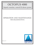
Figure 2-1 depicts the main components of a PC3000 program.
The International Electrotechnical Commission (IEC) have produced a set of
standards for Programmable Controllers. identified as IEC 1131. Part 3 of this
standard, termed IEC 1131-3, specifically addresses PLC languages and the way
PLCs operate and run control programs. Many of the concepts of this standard are
used both in PC3000 and also in other Eurotherm Controls products including the
Production Orchestrator cell controller.
The following languages are available for programming the PC3000 :
Structured Text or ST - a high level language which can be used to express
complex analogue and digital expressions. The language includes support for
complex arithmetic operations, calculations involving times and dates and
conditional expressions using constructs such as IF, THEN, and ELSE. There is
also a comprehensive library that provides functions such as SQRT(), SIN(),
MAX()
Sequential Function Chart or SFC - a graphical language which provides a
diagramatic representation of sequences shown as a series of linked steps and
transitions. SFC is based on the now well accepted Grafcet standard but with
some additional features. It is provides a highly visible method for defining and,
during operation, for analysing the behaviour of the control system, by showing
the active states of the system in the context of all the possible alternative and
parallel sequences.
Function Block Diagram or FBD - a graphical language which
allows program elements called Function Blocks to be
interconnected by simply drawing wires on the screen, i.e. in a
form analogous to designing a circuit diagram using a CAD
system.
2-2
PC3000 User Guide
Programming Concepts
AAA
AAA
AA
A
AAAAAAAAAAAAAAAAAAAAAAAA
AA
A
AAA AAAAAAAAAAAAAAAAAAAAAAAA
AAA AAAAAAAAAAAAAAAAAAAAAAAA
AA AAAA
AAAAAAAAAAAAAAAAAAAAAAAA
AAAAAAAAAAAAAAAAAAAAAAAA
AAAAAAAAAAAAAAAAAAAAA
AA AAAA
AAAAAAAAAAAAAAAAAAAAA
AAAA
AAAAAAAAAAAAAAAAAAAAA
AAAAAAAAAA
AAAAAAAAAAAAAAAAAAAAA
A
A
AA
AAAAA AAA
AAA
A
A
AAA
AA
A
AA
AA
A AAAAAA
AAA
AA
A
AAAAAAAAAAAAAAAAAAAAAA
AAA
AAA
A
AAAAAAAAAAAAAAAAAAAAAA
AAAAAAAAAAAAAAAAAAAAAAAAAAAAA
A
AA
AAAA
AA
AAAA
AA
900
SEQUENTIAL FUNCTION CHARTS
RAMP UP
START
900
SEQ1
SEQ2
COUNT
SEQ3
CHECK
PULSE1
END
BEGIN
Ramp.Mode :=0 (*Reset*);
PID.Reset_Output :=PID.Process_Val;
PID.Output : = 0.0;
PID.Manual : = (*Manual*);
END_STEP
RAMP1
RAMP2
PULSE2
FUNCTION BLOCKS
900
BiSynch_M
Ramp
PV
OP
EuroPanel
Format
Programming Station
has access to all data
on-line
PID
SP
OP
PV
ER
>10
AND
I/O bus
Digital_In
Digital_In
Analog_In
PV
PV
PV
I/O channels
Digital_Out
Digital_Out
Analog_Out
PV
PV
PV
I/O bus
PS
PC3000 User Guide
Digital_In
Digital_In
Analog_In
PV
PV
PV
I/O channels
Digital_Out
Digital_Out
PV
PV
Analog_Out
PV
2-3/4
Programming
Concepts
900
Programming Concepts
Note: FBD programming is only provided by the Microcell
Programming Station.
In accordance with IEC 1131-3, PC3000 allows the control program to be
organised into tasks that run at different execution rates. Normally PC3000 has
two tasks that run every 10ms and 100ms but extra tasks can be created or task
execution rates can be modified to suit the particular process requirements. A task
is a part of a program that is executed periodically.
Many PLCs have a very simple strategy where all the PLC program ( normally
ladder logic expressions) are scanned, i.e. executed, at a fixed scan rate. However,
with PC3000, a program can use processing resources more efficiently if different
parts of the program execute at different scan rates, as dictated by the
responsiveness of the associated plant.
For example, some digital inputs dealing with fast mechanical interlocks may
need to be scanned very rapidly, other digital inputs concerned with say, over
temperature sensors can be scanned more slowly. Typically, analogue inputs are
scanned more slowly than digital inputs. There may also be parts of the application
required to analyse long term trends. In such cases, tasks can be configured to
execute at much slower rates, such as every 5 minutes or longer.
Deterministic performance
Unlike many PLCs, PC3000 provides tasks that have fixed scan rates. For
example, providing certain performance considerations are followed, it is possible
to build a control system in which function blocks assigned to run in a 100 ms task
will always execute every 100 ms. Deterministic Performance is important for
stable and predictable control system behaviour.
If too many function blocks are assigned to a task, PC3000 may overrun, i.e. the
task scan time has to be extended to ensure that the task completes correctly. This
is regarded as an exceptional situation that requires modification of the function
block task assignments.
Further information on using tasks is provided in the PC3000 Real Time Operating
System Reference.
FUNCTION BLOCKS
Traditionally, control systems have been constructed by physically wiring together
a number of discrete instruments, such as, temperature controllers, timers, displays
and so on. However, systems of this type are costly to install and are extremely
inflexible.
In constrast, PC3000 allows control programs to be built-up from "soft
instruments" called function blocks. This powerful concept, formalised by the IEC
1131-3 standard, allows proven software components with functionality similar to
PC3000 User Guide
2-5
Programming
Concepts
Multi-tasking
Programming Concepts
real instruments to be connected together to form complex control systems simply
by software - a concept called "soft-wiring".
A function block contains an "encapsulated" program or algorithm which can be
accessed and controlled externally by a set of parameters. It is "encapsulated" so
that the systems engineer need not be aware of the way the function block has
been designed internally. In fact, the only access to the function block is via a set
of formal parameters provided by the original designer.
Normally a function block will have a set of input parameters which can be used to
connect ( or soft-wire ) to other function blocks. Input parameters can be driven
from live control signals originating from the plant or assigned values by external
devices such as operator stations and supervisory systems.
The input parameters can be used to modify the function block's behaviour . Each
time a function block executes, which depends on the task it is associated with, it
is run using the current input parameters and other internally stored data. The
internal algorithm then updates the output parameters.
Function blocks in some form, have been used in control instrumentation for many
years. For example, the PID algorithms that run is discrete instruments such as
Eurotherm Controls 818 and 900 EPC instruments behave as function blocks. The
PC3000 has an extensive library of function blocks from which the systems and
control engineer can build complex applications. The library includes PID and
Valve Positioner function blocks with auto and adaptive tune, Timers, Counters,
Filters and Bistables. There are also blocks for specific applications, for example,
for building Recipe Management systems, for communicating with other
proprietary devices such as PLCs and for real-time Statistical Process Control
(SPC). With function blocks you are able to "plug and play" and develop new and
novel solutions to process problems.
2-6
PC3000 User Guide
Programming Concepts
Function block example
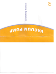
Figure 2-2 depicts a Ramp Function Block which can be used wherever there is a
requirement to generate a value that increases at a constant rate. The Ramp
function block will ramp the output parameter ( actually called Output ) towards
the value of the Setpoint input parameter at rate determined by the Rate input
parameter.
Inputs
Programming
Concepts
Func tion block type
Outputs
Ramp
ENUM
Mode
RE AL
Output
R EAL
Setpoint
Ramp_End
BOOL
REA L
Rate
Ramp_Act
BO OL
REA L
Reset_Output
HB_Active
BOOL
EN UM
HB_Mode
REA L
HB_Deviation
RE AL
Process_Val
EN UM
Rate_Units
Parameter
data types
Parameter
data types
Figure 2-2 Function Block Example
The function block also supports a hold-back mode whereby the Output can track
the value of the process value, i.e. the Process_Val parameter, within a given
deviation. This may be useful for example, when ramping a furnace temperature
when the difference between the furnace setpoint temperature and actual
temperature should stay within certain limits.
Each function block parameter is associated with a particular data type which
defines the type and range of values that the parameter can store. A wide range of
data types are provided including REAL parameters which are used for decimal
(floating point) values such as 12.54, 0.0541, - 1220.1 ; BOOL parameters which
have two states such as ON/OFF, TRUE/FALSE, UP/DOWN ; ENUM parameters
which can have a number of named or enumerated states, for example the Mode
parameter of the Ramp function block has states Reset, Run and Hold. Other data
types are provided for holding counts, messages and dates and times.
Full details on Data types are given in chapter 3.
In PC3000 it is possible to create many copies of the same function block type. For
example, you may wish to have three ramp function blocks to control three
different control variables such as, pump rate, temperature and pressure. The
PC3000 User Guide
2-7
Programming Concepts
copies can be given unique names e.g. RampPump, RampTemp, RampPres .
Copies of a particular type of function block are referred to as function block
Instances. When a new copy of a function block is created, all input parameters
are given a standard set of default values. In many cases, these values can be left
unchanged where the default values suit your application or if a particular feature
of the function block is not required.
All values assigned to input parameters as constants, e.g. setting a PID Prop_Band
parameter to 6.00 %, are used to reset the function block when it is initialised, i.e.
used for Cold Start values.
When PC3000 runs, each function block copy or instance, runs entirely
independantly of any other instance. For example, RampPump could be in Hold
state, while RampTemp and RampPres are ramping to different setpoint values.
When a function block executes, the output values will, in many cases, change for
each execution, even when the value of all the function block's input parameters
are left unchanged. This is because the function block has internally stored
variables that are used to accummulate values for counters, integrated values etc.
For example, while the Ramp function block is in Run mode, the Output will
increase on each subsequent function block execution until the ramp setpoint is
reached although all the input parameters remain unchanged.
I/O Function blocks
For consistency, the gathering of input values from sensors and delivering output
signals to actuators, heaters etc. is handled by input/output (I/O) function blocks.
For example, the analogue input function block Analog_In provides a range of
input parameters that configure the sensor type, and scale the input value to
handle a wide range of input sensor types including most types of thermocouple.
The input sensor value is provided by the function block's Process_Val output
parameter in process units such as degrees C, millibars etc. Note that this function
block also provides a test facility to override the current plant input value with a
test value.
Each I/O function block is associated with a particular hardware I/O channel
defined by an input parameter called IO_Address. This defines the I/O channel's
physical location by rack number, module number and channel.
For example an I/O channel function block for the second channel of a
hardware module in position 3 of rack 1 has an I/O address : 1:03:02
I/O addresses are automatically given by the PC3000 Programming Station when a
channel is assigned. It is not possible to directly change the value of the I/O
address parameter, but the I/O channel function block can be moved to a different
hardware module.
For further information on the Ramp and Analog_In function blocks refer to the
PC3000 Function Block Reference.
2-8
PC3000 User Guide
Programming Concepts
The PC3000 user program for a particular control application, consists of a
number of inter-connected function blocks to provide the continuous control
aspects of the system and one or more Sequential Function Charts (SFCs) to define
the sequential aspects. The SFCs contain actions that can modify the values of
function block input parameters in response to certain events. SFCs are therefore
able modify the system behaviour according to well defined changes in specific
process conditions, such as reaching operating temperature, or emptying a reactor
vessel.
The function blocks are partitioned into tasks that execute at fixed scan rates. The
default task configuration which is suitable for a large number of PC3000
applications, has two tasks named Task_1 and Task_2,which execute every 10
ms and 100 ms respectively. Most function blocks associated with analogue I/O
and analogue control are run every 100 ms; this includes the PID function blocks.
The rest, i.e. those associated with digital signals and therefore requiring a faster
system response are run every 10 ms. The Sequential Function Charts (SFCs) by
default are run in the slower 100 ms task .
Task Name
Task Scan Rate
Task_2
100 ms
Purpose
All analogue related function blocks
Most analogue I/O function blocks
All Sequential Function Charts
Task_1
10 ms
All digital related function blocks
All digital I/O function blocks
Fast analogue I/O function blocks
Table 2-1 Default Task Configuration
However, the default task configuration can be modified if the control problem
has some special requirements. All function blocks including those for I/O can be
assigned to run at other scan rates by changing the task scan times or by creating
additional tasks. This may be necessary, for example, when there is a need to
increase the responsiveness of certain inputs by shortening the task scan times or
alternatively a need to reduce system overheads by increasing the scan rates of
certain function blocks.
Caution:
Care should be taken when modifying task configuration
parameters or task assignments as this may affect the control
system responsiveness or produce unexpected side-effects. The
PC3000 Programming Station automatically assigns function
blocks to the two default tasks. Therefore modification to the task
configuration is not normally required.
Refer to the PC3000 Real Time Operating System Reference, Chapter Real Time
Task Scheduler for details on configuring tasks.
PC3000 User Guide
2-9
Programming
Concepts
PROGRAM EXECUTION PRINCIPLES
Programming Concepts
SEQUENTIAL FUNCTION CHARTS
Sequential Function Charts (SFCs) consist of two basic constructs, steps and
transitions as depicted in Figure 2.3.
Step_A
Step
Transition
Step_B
A Step defines a set of
actions that are performed
when the control program is
in a certain state. A step
remains active until a
following Transition
becomes true. A transition
is defined by a test
condition which must result
in a true or false result; for
example, that a particular
digital input from a microswitch is "on".
Figure 2-3 Sequential Function Charts Constructs
In Figure 2-3 , if Step_A is active, then Step_B will become active and Step_A
inactive when the condition for the Transition from Step_A to Step_B becomes
true.
When the SFCs are evaluated ( normally by default every 100 ms ), only the
conditions of transitions from active steps are tested. In a well designed program,
it is generally found that only a small number of steps are actually active at any
time. As a consequence, PC3000 is able to execute complex programs, having
SFCs with a large number of steps and transitions, without any significant
performance overhead.
Actions within steps can be defined in Structured Text (ST) or in terms of further
SFCs. Examples of ST statements to define actions within steps are :
loop1.Setpoint := 400.0;
tempRamp.Mode := 1 (* Run *);
vacpump.Process_Val := vacpump.Process_Val
+ 12.50 ;
Each Transition is defined by a condition expressed in Structured Text such as,
pumpswt.Process_Val = 1 (* On *) AND
O2valve.Process_Val = 1 (* Open *);
2-10
PC3000 User Guide
Programming Concepts
In this example, two digital inputs pumpswt and O2valve provide the states of two
digital process variables. So the transition condition can be read as "pump switch
is on and oxygen valve is open"
Note: On the Microcell Programming Station alternative graphical
programming methods are provided including Spreadsheets and
Function Block Diagrams.
SOFTWARE OVERVIEW
An application program for PC3000 consists of two main sections, 1) Function
Blocks and their associated wiring to provide the continuous control and logic
functions and 2) Sequential Function Charts to handle sequencing.
Figure 2.1 shows how these program sections interact with the PC3000 hardware
that provides the interfaces to I/O sensors and actuators and communications with
external devices. The figure shows a few examples of the many different types of
function blocks provided with PC3000.
The interfaces to I/O is provided by I/O function blocks such as Digital_In and
Analog_Out. The PC3000 I/OBus provides a two-way information exchange
between these function blocks within the PC3000 application program and the I/O
channels of the hardware I/O modules.
The PC3000 Programming Station ( and MicroCell ) has access to all Function
Block parameters while the PC3000 is running using the Eurotherm
communications protocol Bisync. This facility is referred to as "default
communications" and is always available for diagnostic and program development
purposes.
Communications with other external devices is provided by communications
driver function blocks such as Bisync_M and Euro_Panel. In figure 2-1, the
Bisync_M function block is associated with a communications port linked to a
number of multi-dropped instruments; in this case, using the Eurotherm Bisync
protocol. The figure also shows an operator panel connected using the EuroPanel
function block. A wide range Function Blocks for other protocols such as
JBus/Modbus are also provided. This allows a large number of different types
communicating devices to be connected to PC3000.
Refer to the PC3000 Communications Overview document for further information
on communicating with external devices.
PC3000 User Guide
2-11
Programming
Concepts
For further details refer to Chapter 3 Structured Text. and Chapter 4 SFC
Programming.
Programming Concepts
PROGRAM EXAMPLE
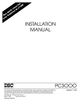
Figure 2.4 depicts a simple program example that demonstrates many the PC3000
programming concepts. The program uses a single PID control loop to drive a heat
process and changes the setpoint for the control loop by a small sequence program.
This program is used to introduce the PC3000 programming techniques and is
therefore intentionally simplistic but it will function.
Continuous Control
The single channel control loop is constructed by "soft-wiring" an analogue input
channel function block (Temp1) to a PID block (Loop1) which in turn, then
provides an output signal to an analogue output channel function block (Heat1).
The configuration parameters which are required to customise the input and output
channel blocks to match the sensor and actuator characteristics and the PID tuning
parameters are not shown in figure 2.4 to aid clarity.
To construct the "continous control" part of the program, the main actions are :
1. Allocate hardware modules and channels for the analogue input and output
using the hardware configuration screen; for example, using modules such as AI4
and AO4 .
In this example, the analogue input is driven by channel 1 of module 2, and the
output drives channel 2 of module 4, both in rack 1.
2 . Assign values for the configuration parameters to customize the input and
output. The analogue input channel will normally require values for the following
parameters :
Input_type e.g. Range_3. Check the Data sheet for the range supported by a
particular hardware module. In this case, Range_3, selects -10 to 50mV operation.
Lin_Type to set the linearisation type e.g. J for a type J thermocouple
CJC_Type to set the type of Cold Junction Compensation e.g. intern for internal.
Pre_Scaler, Pre_Offset , Post_Scaler, Post_Offset to set the scalers to scale and
offset the input signal before and after linearisation. These parameters are used in
conjunction with PV_Max and PV_Min to produce the required engineering
units.(ie. 0 to 100 degrees C ). The values 1.0 and 0.0 for both scalers and offsets
should be suitable for this example. E.g. Post_Scaler to 9/5 and Post_Offset to 32
would produce a value in degrees F. With Post_Scaler set to 1 and Post_Offset to 0
will produce a value in degrees C.
2-12
PC3000 User Guide
Programming Concepts
Task2 100ms
(Analog_In)
1: 0 2: 0 1
(Analog_Out)
(PID)
T em p1
Loop1
Process_Val
IO_Address
Process_Val
1 : 04 : 02
Ch1_Output
H e at1
IO_Address
Process_Val
Programming
Concepts
Setpoint
"Soft-Wiring"
Task2 100ms
Sequential function chart
Setup
Loo p1.Se tpoin t:= 2 0.0;
AB S_REA L(Tem p1.Pr ocess _Val - Loo p1.Se tpoin t) < 2.0
Heatup
Loo p1.Se tpoin t:= 6 0.0;
Tem p1.Pr ocess _Val> 56.0 AND H eatup .Time >= T# 30s
Cool
Loo p.Set point := 20 .0;
Temp 1.Pro cess_ Val<2 4.0
F inish
Figure 2-4 Simple Program Example
PV_Max, PV_Min set these to define the acceptable range of values for the input
eg. 0 to 100.
Note: If PV_Max is left at 0, the analogue input status Act_Status
may be set to NOGO because the input value is out-of-range.
The analogue output channel function block requires a value for Output_type to
define the range of the output actuator, or drive e.g. mA4_20 for 4 to 20
milliamps.
3. The PID function block also requires the following configuration parameters :
Span_High, Span_low set these to match the range of the analogue input.
Output_High,Output_Low ensure these are set to 100 and 0 percent. If
Output_Low is set to -100 percent, the PID will function in dual channel mode
(heat/cool).
Prop_Band, Integral and Derivative set these as required by the controlled
process.
PC3000 User Guide
2-13
Programming Concepts
Manual set to Auto to switch the PID into automatic mode.
4. Construct the "soft-wiring" to link the three function blocks, i.e. :
Loop1.Process_Val := Temp1.Process_Val;
and
Heat1.Process_Val := Loop1.Ch1_Output;
When using the PC3000 Programming Station, these statements are attached to the
input parameter of the function block to receive the value; in this case Loop1 and
Heat1.
Note: Wiring statements are created at the DESTINATION
parameter
Further details on hardware configuration may be found in the PC3000 Hardware
Reference handbook.
The continuous control part of this simple example is now complete and if this
program is now compiled, built and downloaded into the PC3000, the three
functions blocks will behave as a simple single loop controller. The loop setpoint
can be set by changing the PID input parameter, Loop1.Setpoint .
Sequencing
The control loop is sequenced by a small SFC with steps; Setup, Heatup, Cool and
Finish.The Structured Text for each Step and Transition is shown alongside the
SFC in figure 2-4. The Setup step establishes an initial setpoint of 20.0 and waits
for the process value to settle. During the Heatup step, the process is driven to a
higher setpoint of 60.0. The Heatup step continues until the process value has
reached a threshold value of 56.0 and has been active for period of more than 30
minutes. The Cool step is then activated which changes the setpoint back to 20.0.
When the process value has cooled to below 24.0, the SFC terminates by entering
the Finish step.
To program the SFC using the Programming Station the following actions are
required :
1. Use the SFC editor to create a four step SFC in the main chart. The first step
should be defined as a "start" step and given the name Setup. Also name the other
steps Heatup, Cool and Finish. The Finish step should be defined as an "end" step.
2. All three steps should be defined as "single shot" implying that they will only
execute once when the steps are first entered.
3. Enter the Structured Text for each step and transition as shown in figure 2-4.
Note that the transition from Start to Heat uses the function ABS_REAL which is
used to calculate the absolute value of the PID error parameter.
The condition for the second transition uses the AND operator to check that
a) the process value is greater then 56.0 and
b) the Heatup step has been active for longer than 30 minutes.
The duration of any active step is provided by the step's Time ( abbreviated .T )
output parameter.
2-14
PC3000 User Guide
Programming Concepts
The PC3000 mode is displayed on the main menu of the PC3000 Programming
Station when in on-line mode. Use the command RUN to switch the PC3000 into
the RUNNING mode.
All the function blocks in this example are associated with analogue control and
all execute in Task2 which by default runs every 100 ms. The SFC also executes
in the same task but remember that only the active step and it's associated
transition conditions are evaluated every 100 ms.
For further system details on timing and execution of SFCs and function blocks
refer to PC3000 Real Time Operating System Manual.
Digital Logic
To complete this example, figure 2-5 shows how a simple alarm condition can be
added by using digital function blocks. These are inter-connected using soft wiring
in exactly the same way as the analogue blocks. The example assumes that an
alarm signal is required to switch off power to the process, whenever either of two
doors (Door1 and Door2) are opened and the temperature of the process is greater
than 50.0.
I/O channel function blocks for digital inputs Door1 and Door2 provide the state
of doors, for example, by connecting the hardware digital inputs to microswitches. The alarm output signal is driven by a digital output function block,
Alarm.
The Alarm Process_Val input parameter is "soft-wired" using an ST expression
that involves both the process value of the digital input function block and the
Temp1 function block. Soft-wiring can either provide direct point-to-point links as
used to construct the control loop, or can involve complex expressions with both
digital and analogue function block parameters.
PC3000 User Guide
2-15
Programming
Concepts
To test the program - compile, build and download the program into the PC3000.
With the PC3000 switched into RUNNING mode, the program will execute by
sequencing through steps Setup to Finish setting the PID setpoint. Note that on
reaching the Finish step, the SFC terminates with no further active steps.
However, the function blocks for the control loop continue to execute. With this
simple example, it is necessary to RESET the PC3000 and then switch the PC3000
back into RUNNING mode to re-start the SFC. It is possible to construct the SFC
so that it always re-starts, this is discussed in Chapter 4 SFC Programming.
Programming Concepts
Task1 10 ms
Temp1.Process_val
50 .0
>
AND
(Di gital _In)
1:03:01
D oor1
Process_Val
IO_Address
(Digi tal_O ut)
1:05:01
Ala rm
IO_Address
Process_Val
OR
(D igita l_In)
1:03:02
Do or2
Process_Val
IO_Address
"Soft-wiring"
Alar m.Pro cess_ val:= (Do or1.P roces s_Val OR
Doo r2.Pr ocess _Val) AND
Tem p1.Pr ocess _Val> 50.0;
Figure 2-5 Digital Logic Example
To create these function blocks and soft-wiring, the following actions are required:
1. Create two I/O digital input channel function blocks named Door1 and Door2
using a hardware module such as DI14_CON. There are no channel configuration
parameters to set-up. Ensure that the Test_Enable parameter for each block is Off,
i.e. the default value.
2. Create a digital output channel function block named Alarm using a hardware
module such as DO12_RLY. Ensure that the Test_Enable parameter is Off, i.e.
the default value.
3. Select the Alarm.Process_Val parameter and attach the soft-wiring Structured
Text statement as shown in figure 2-5 .
The digital function blocks are assigned to Task 1 which runs every 10 ms. The
soft-wiring connected to the process value of the output function block Alarm, is
also evaluated every 10 ms i.e. the same as the Alarm function block.
The example program is now complete and can be compiled, built and
downloaded into the PC3000. The control loop and alarm digital logic are
2-16
PC3000 User Guide
Programming Concepts
executed continously while PC3000 is in RUNNING mode. The sequencing will
proceed through the four steps starting from Setup. Table 2-2 depicts the execution
order that is automatically created by the Programming Station to run the program.
In most cases, detailed knowledge of the execution order is not required.
Every 10 milliseconds -
Programming
Concepts
Read the hardware digital input channels Door1 and Door2
Execute the digital I/O channel function blocks and the alarm digital
logic soft-wiring.
Write the Alarm output value to the digital hardware channel.
Every 100 milliseconds Read the hardware analogue input channel Temp1
Execute function blocks Temp1, Loop1 and Heat1 and the softwiring forming the control loop.
Execute active SFC steps and evaluate transition conditions
following active steps.
Write out the output value to the analogue hardware channel.
Table 2-2 Example Program Execution Order
SOFT-WIRING PERFORMANCE CONSIDERATIONS
When designing large PC3000 programs it is important to appreciate that a large
number of soft-wiring statements can present a significant performance overhead.
Note: Each soft-wiring ST statement is executed at the same rate
and in the same task,as the function block receiving the value
produced by the soft-wiring.
Care should therefore be taken to minimise the number and complexity of softwiring statements assigned to function blocks that have a high scan rate,
particularly digital function blocks. Soft-wiring containing a large number of
operations involving floating point values, such as comparing Temp1.Process_val
with 50.0 used in the previous program example, presents a significant
performance overhead. With good program design, the number of floating point
calculations can be reduced.
In contrast, a large number of operations involving digital parameters, such as the
OR of door1.Process_val and door2.Process_val used in this example, can be
executed without any significant overhead.
More guidance on good program design is given in Chapter 5 Program
Development. Detailed information on performance is also given in the PC3000
Real Time Operating System Reference Appendix C.
PC3000 User Guide
2-17
Chapter 3
STRUCTURED TEXT
Edition 1
Contents
OVERVIEW .................................................................... 3-1
Introduction to structured text .................................... 3-1
WHERE TO USE STRUCTURED TEXT............................... 3-9
ASSIGNMENTS ............................................................ 3-10
Expressions ............................................................ 3-10
Complex expressions .............................................. 3-11
STATEMENTS............................................................... 3-12
Conditional Ssatements .......................................... 3-12
OPERATORS ................................................................ 3-14
Arithmetic operation ............................................... 3-14
Comparison operators ............................................ 3-16
Boolean operators .................................................. 3-17
Operator precedance ............................................. 3-18
BOOLEAN EXPRESSIONS ............................................. 3-19
FUNCTIONS ............................................................... 3-20
VALUE SELECTION ...................................................... 3-21
Selection functions .................................................. 3-21
Value selection using IF construct............................. 3-23
RULES FOR WRITING VALID STRUCTURED TEXT............ 3-24
PC3000 User Guide
Cont. i
Structured
Text
Comments ............................................................... 3-2
DATA TYPES ...................................................................3.2
Structured Text
OVERVIEW
This Chapter discusses :
• The features of the Structured Text language
• Where Structured Text can be used in PC3000 programs
• How different types of data can be handled in Structured Text
• How to use functions within Structured Text
• Good Programming style for Structured Text
Introduction to structured text
Structured
Text
Structured Text ( abbreviated as ST ) is a high level textual language which has
been formalised by the IEC 1131-3 PLC Programming Languages standard for
use in programming controllers for industrial manufacturing processes. ST
provides a wide range of features that make it particularly suitable for
programming the control of industrial processes.:
• All variables used within the language can be given meaningful names such as:
pumpRate.Setpoint
heat1.Output_Type
• Both simple and complex expressions for mathematical calculations can be
clearly expressed, e.g.
FlowRate.Val := FanSpeed.Process_Val * 3.5;
• Conditional expressions, i.e. for
values that are derived from tests of some form,
are well supported. For example, to deal with requirements such as: "The motor
speed is 200 r.p.m. when the casting is less than 5 Metres from the tool-head
otherwise the speed is 20 r.p.m." can be expressed as:
IF Position.Val < 5.0 THEN
Motor.Process_Val := 200;
ELSE
Motor.Process_Val := 20.0;
END_IF;
• A wide range of different types of data can be used including floating point and
digital values, times, time of day and dates. There is also provision for handling
textual messages.
• Expressions involving different types of data are possible, e.g:
gas.Process_Val := Zone1.Process_Val > 310.4
• A wide range of range of standard built-in operators are provided such as :
+,-,*,>,<,AND,OR,NOT
PC3000 User Guide
3-1
Structured Text
• The language has built-in safe-guards to prevent illogical operations between
different types of data. For example, it is not possible use mathematical operations
with digital input values, or logical operators such as AND with analogue values.
• Functions can be used to ease, otherwise complex program expressions, eg:
position.Val := SQRT(X.Val*X.Val + Y.Val*Y.Val);
position.Val := SQRT(X.Val*X.Val + Y.Val*Y.Val);
In general, fairly simple Structured Text statements are adequate when
programming the majority of PC3000 control applications. However, the PC3000
Programming Station does allow large complex pieces Structured Text to be
created if required. There are limits to the maximum size of an individual piece of
ST but this is sufficiently generous that normally it is of no practical significance.
When programming PC3000, ST is used to describe :
a) "soft-wiring" to inter-connect function blocks,
b) the actions within SFC steps
c) the conditions for SFC transitions.
Certain restrictions apply to ST when used for these different purposes; these are
discussed in more detail later in this chapter.
Comments
To aid readibility, comments can be freely added to ST statements by enclosing
text with the characters (* and *). Examples are :
(* This step starts up reactor 2 *)
(* Modified to optimise energy usage *)
DATA TYPES
PC3000 supports a range of data types within Structured Text that cover most of
the processing requirements for production process control. Writing ST
expressions that use these different types of data is discussed in later sections of
this chapter.
Note: throughout this user guide, where an informal data type
decription is given, the formal IEC data type name is sometimes
given in parenthesis.
3-2
PC3000 User Guide
Structured Text
Floating Point (REAL)
Range
Size in Bits
+10+38
32
Purpose
Gerneral purpose data type for all
floating point i.e. decimal values
This data type is used for storing all analogue floating point values both positive
and negative values, and large and very small fractional values, e.g. 100.56,
100245.21, -0.000233
Integer (DINT)
Size in Bits
-2147483648 to
32
+2147483647
Purpose
Gerneral purpose data type for
holding integer values, eg. for
counters.
This is used for holding integer values , i.e. whole numbers and is used for counts,
batch numbers etc. A large range of positive and negative values can be stored
e.g. 12, 1235687, - 100040.
Enumerated Integer (DINT)
Range
Size in Bits
-2147483648 to
32
+2147483647
Purpose
Gerneral purpose data type for
holding integer values that have a
defined set of named values, eg. for
modes, status
This data type ( sometimes abbreviated as ENUM) uses the same storage size as a
the integer (DINT) but has names associated with a defined set of values. These
names are displayed on the PC3000 Programming Station and are provided to aid
readability.
PC3000 User Guide
3-3
Structured
Text
Range
Structured Text
For example, the PcsSTATE function block which defines the current state of
the PC3000 control system has an output parameter Battery_Cond (battery
condition) that is an enumerated integer. This has named states :
Good
(0)
Low
(1)
Faulty (2)
The appropriate name is displayed on the PC3000 Programming Station when the
value of the parameter is viewed.
Enumerated integers can be freely used together with normal integers in ST
expressions.
Boolean (BOOL)
Range
Size in Bits
Purpose
0 or 1
1
Gerneral purpose data type for storing
boolean values, i.e. 0 or 1.
This data type is used to store boolean values, such as those associated with digital
inputs for switch contacts, which can have two states of value 0 and 1. Normally 0
is associated with "Off" or "False" and 1 is associated with "On" or "True". The
PC3000 Programming Station however allows boolean values to be given
alternative sense names if required. The sense names are used to aid program
readibility.
3-4
PC3000 User Guide
Structured Text
Examples are :
Down (0)
Up (1)
In (0)
Out (1)
Duration (TIME)
Range
Size in Bits
Purpose
Up to 49 days
32
Used specifically for storing time
durations, such as job durations, PID
time constants
Structured
Text
This data type is used to store time durations accurately to the nearest
millisecond. Any duration for up to 49 days can be stored. When viewed on the
Programming Station, durations are displayed using the IEC format. Examples
are:
T#2d_01h_30m (* 2 days, 1 hour, 30 minutes *)
T#3s200ms (* 3 seconds and 200 milliseconds *)
The use of the prefix T# in ST indicates that these are constants of TIME data
type. The prefix is automatically inserted by the Programming Station.
Time of day (TIME_OF_DAY)
Range
Size in Bits
Purpose
00:00:00 to
23:59:59
32
Used specifically for storing values
for the time of day i.e. 24 hour clock.
This data type is used wherever there is a need to store the time of day. For
example, to define the time of day to start a particular job or task. Values are
stored to an accuracy of one second and displayed on the Programming Station in
24 hour clock format .
Examples are :
TOD#09:30
TOD#13:45
(* 9:30 in the morning *)
(* 1.45 in the afternoon *)
The use of the prefix TOD# in ST indicates that these are TIME_OF_DAY
constants. The prefix is automatically inserted by the Programming Station.
PC3000 User Guide
3-5
Structured Text
Calendar Date (DATE)
Range
01-Jan-1970 to
Size in Bits
32
01-Jan-2136
Purpose
Used specifically for storing values
for calendar dates
This data type is used for storing calendar dates. A wide range of dates are
supported.
Examples are :
D#28-Jul-1992
D#01-Jan-1993
The use of the prefix D# in ST indicates that these are date constants. The prefix
is automatically inserted by the Programming Station.
Calendar Date and Time of day (DATE_AND_TIME)
Range
01-Jan-197000:00:00 to
Size in Bits
32
01-Jan-213623:59:59
Purpose
Used specifically for storing values
for calendar dates combined with
time of day
This data type is used for storing calendar dates along with time of day and is
typically used to store "time stamps" for key events such as when jobs start, when
alarms are raised, when operator shifts are changed etc.
Examples are :
DT#02-Sep-1992-20:30:00
DT#25-Jan-1991-23:00:30
The use of the prefix DT# in ST indicates that these are date DATE_AND_TIME
constants.The prefix is automatically inserted by the Programming Station.
3-6
PC3000 User Guide
Structured Text
Textual strings (STRING)
Range
Each character can
hold any character
from the ASCII
code set. Non
ASCII codes from
hexadecimal values
$80 to $FF are also
supported.
Size
The length of a
textual string is
variable - see
description
Purpose
General purpose data type used for
storing textual information consisting
of a string of characters.
For example, the String User Variable function block can store textual strings of
up to 80 characters, whereas the Long_String User Variable function block can
be used for strings up to 255 characters.
For further information on User Variable function blocks refer to the PC3000
Function Block Reference.
Examples of textual strings are :
'Batch 723XA' (* Current Batch Identity *)
'0A01 PV' (* Address Port 0A, instrument 1 PV *)
'ADD REAGENT X1' (* Operator Message *)
Strings in ST are enclosed between apostrophe characters. These characters are
automatically inserted by the Programming Station when a string constant is
created.
It is possible to insert a non-printable character into a string by typing a dollar $
sign followed by the ASCII code in hexadecimal. E.g. to insert the bell character
that will produce an audible sound on some operator stations type $07. The full
ASCII code is given in the PC3000 Function Block Reference. Non-printable
characters may be required to format textual messages to be issued to a printer.
Additional Integer Data Types
The majority of integers used in PC3000 function blocks and functions are of the
DINT data type. However in a few rare cases parameters can be defined using
integer data types listed in table 3-1.
PC3000 User Guide
3-7
Structured
Text
This data type is used for holding textual information such as operator messages,
printer report messages, communication addresses, batch descriptions etc. The
length of the string, i.e. the maximum number of letters and digits (characters) that
can be stored depends on usage.
Structured Text
IEC Data Type
Description
Size in Bits
Range
SINT
Unsigned Short
Integer
8
-128 to 127
USINT
Unsigned Short
Integer
8
0 to 255
INT
Unsigned Integer
16
32768 to
-32767
UDINT
Unsigned Double
Integer
32
0 to 42944967296
Table 3-1 Additional Integer Data Types for Function Block Parameters
The Table 3-1, data types described as "unsigned" imply that only positive values
can be stored.
Caution
Care should be taken when assigning integer values created by ST
expressions, to integer parameters that are not of the normal DINT
data type. The range of the integer value created by the ST must
be within the range of the data type of the parameter to receive the
value. If the value is out-of-range an incorrect value may be
assigned, e.g. assigning the DINT value 300 to a USINT will fail
because the USINT maximum value is 255.
Note: These additional integer data types are not used in any of the
standard PC3000 function blocks or functions with the exception
of the string functions LEN, LEFT, RIGHT,MID, INSERT,
DELETE, REPLACE, FIND, JUSTIFY_LEFT, JUSTIFY_RIGHT,
JUSTIFY_CENTRE which have some USINT integer parameters.
Descriptions of functions and function blocks in the PC3000 Functions and
Function Blocks References include the data type of each parameter.
IO Address
The I/O Address data type is used to store the physical position of an I/O channel
function block. This is a special PC3000 data type which is not defined by the IEC
standard. It is not possible to manipulate parameters of this type in ST since this
would serve no practical purpose.
Note that I/O channel function blocks can be assigned to different
physical addresses by using facilities provided by the Programming
Station on the Hardware Definition screen.
I/O Address parameters are discussed in Chapter 2, PC3000 Programming
Concepts.
3-8
PC3000 User Guide
Structured Text
Data Type Conversion
A wide range of functions are provided to convert between data types; refer to the
PC3000 Functions Reference, Chapter Type Conversion Functions for the full list.
For example, a count held as an integer may be required in an expression to
calculate the value of an analogue output. In this case, the function
DINT_TO_REAL can be used to convert the integer value into a floating point
(REAL) value, i.e.
height.Process_val :=
DINT_TO_REAL(count) * 100.5;
Structured Text can be used for three different purposes in a PC3000 program but
in each case, the basic structure of the language is the same.
Usage
Soft-wiring
Step Actions
Purpose
Language Constructs
Inter-connection of Function
Blocks
Assignments
Assigning new values to
Function Block Parameters
Assignments
Expressions
Expressions
Statements
Conditional Statements
Transition
conditions
Defining a condition that
when "true" causes a new
step (or steps) to be active
Expressions
Table 3-2 Use of Structured Text
Structured Text provides a few, simple easy-to-learn, constructs - Assignments,
Statements, Expressions and Conditional Statements which when used together,
result in a flexible and expressive language. In order to produce efficient PC3000
programs, you are advised to become familiar with the following language
constructs.
ASSIGNMENTS
Structured Text assignments allow new values to be written to Function Block
input parameters. These values can be constants, the value of other parameters, or
derived from other parameters using expressions. Assignments are used to interconnect function blocks, i.e. in soft-wiring, and to define new parameter values in
SFC steps.
PC3000 User Guide
3-9
Structured
Text
WHERE TO USE STRUCTURED TEXT
Structured Text
Examples are :
loop1.Setpoint := 30.5;
count1.Process_Val := 300;
pulse3.Prog_Time := T#1s;
heat1.Process_Val := loop1.Output;
speed.Process_Val := rate.Process_Val * 20;
An assignment always starts with the name of the Function Block input parameter
on the left-hand side followed by the symbol ":=".
The value of the right-hand side ( i.e. following the ":=" symbol) should result in a
value of the same data type as the function block input parameter. The assignment
text is always terminated by a semicolon ";".
When creating "soft-wiring" assignments, the Programming Station automatically
inserts the ":=" and ";" symbols.
Note: The Programming Station will report "Error Invalid ST" if
an assignment is made to any function block output parameter.
Assignments to input/output parameters are allowed.
When an assignment is used to inter-connect or "soft-wire" function blocks as part
of the continous control strategy, remember that the assignment will be evaluated
continously. That is, at the task scan rate of the function block to which the
asignment is being made.
Expressions
A wide range of expressions can be created using the standard ST operators so that
derived values can be calculated from parameters of the various ST data types.
Expressions are used in the right-hand side of assignments and in conditional
expressions. A typical simple expression involves one or two parameters or
constants and an operator.
Examples of simple expressions :
123 + 34.6
10000 * count.Process_Val - loop1.Setpoint
NOT switch.Process_Val
3-10
PC3000 User Guide
Structured Text
Examples using simple expressions in assignments :
(* Add 120.0 degrees to the current soak
temperature *)
soakTemp.Setpoint := soakTemp.Setpoint + 120.0;
(* The line rate is 2 M/S plus 50% the conveyor
speed *)
lineRate.Process_Val := 2.0 +
conveyor.Process_Val * 0.5;
Complex expressions
In some cases it may be necessary to build-up complex expressions involving
many parameters and operators. A complex expression is composed of many subexpressions each of which , in turn, may be composed of further sub-expressions
or simple expressions. To clarify the execution order of complex expressions,
round brackets "(", ")" can be used to identify the sub-expressions.
Examples :
(( airPress.Val * 13.54 )
+ ( gasPress.Val * 34.32 )
- ( vapPress.Val * 0.5 ))
(switch.Process_Val AND dig3.Process_Val)
OR
(overpress.Process_Val AND noAlarm.Val)
PC3000 User Guide
3-11
Structured
Text
(*Valve is ON if O2 supply is OFF and H2 is ON*)
valve.Process_Val := NOT O2.Process_Val AND
H2.Process_Val;
Structured Text
STATEMENTS
A section of Structured Text is composed of a number of statements. An
assignment is one example of a simple ST statement. Conditional Statements are
more complex and allow sets of ST statements to be selectively executed - as
described in the next section.
In an SFC step, a variety of statements can be used to set up the values of function
block input parameters as required for the particular process phase or state.
Example :
BEGIN
heater1.Process_Val := 123.0;
heater2.Process_Val := 130.0;
fan.Process_Val := 1 (* ON *);
END
Note : The keywords BEGIN and END are automatically added by
the Programming Station when Structured Text for a step is
created. They indicate that the ST defines step actions
Conditional statements
A set of statements can be conditionally evaluated using a conditional statement
structure. The PC3000 Structured Text provides the IF, THEN, ELSIF, ELSE and
END_IF keywords to allow you to conditionally select statements according to
certain control criteria.
In the simplest form, IF, THEN and END_IF can be used to conditionally select a
set of statements.
Example:
IF switch.Process_Val = 1 (* COOL *) THEN
fan.Process_Val := 1 (* ON *);
fanSpeed.Process_Val := 230.0;
END_IF;
The expression between the IF and THEN keywords can be either simple or
complex but must result in a boolean (BOOL) result, i.e. the expression must
generate a value that can only be "True" (1) or "False" (0). This is known as a
boolean expression.
In the example, the assignments to fan.Process_Val and fanSpeed.Process_Val
only occur when switch.Process_Val has the value 1, otherwise the assignments
are ignored. All the ST between the IF and the END_IF is known as a conditional
IF statement and like other statements, it must be terminated with semicolon ";".
3-12
PC3000 User Guide
Structured Text
Using the ELSE keyword, alternative statements can be evaluated.
Example:
IF switch.Process_Val THEN
gasFlow.Process_Val := 100.0;
almEnable.Val := 1 (* ON *);
ELSE
gasFlow.Process_Val := 30.0;
almEnable.Val := 0 (* OFF *);
report.Val := 'STANDBY';
END_IF;
Because switch.Process_Val produces a boolean value, it can be used as the
conditional expression in the IF...THEN construct.
The ELSIF ... THEN construct can be used to select one or more further sets of
alternative statements.
Example:
IF count = 0 THEN
speed.Process_Val
door1.Process_Val
ELSIF count < 10 THEN
speed.Process_Val
door2.Process_Val
ELSE
speed.Process_Val
door3.Process_Val
END_IF;
:= 20.0;
:= 0 (* SHUT *);
:= 40.0;
:= 0 (* SHUT *);
:= 60.0;
:= 0 (* SHUT *);
In this case, if count is zero, the first set of assignments are made, if the count is
less than 10 but not zero, the second set of assignments are made. Otherwise, the
last set are made.
Where there is an IF... THEN construct followed by multiple ELSIF ... THEN
constructs, only the set of statements associated with the first true conditional
expression is evaluated.
Note: It is good practice to ensure that multiple ELSIF constructs
have mutually exclusive conditions to ease program readability.
PC3000 User Guide
3-13
Structured
Text
In this example, the assignments to gasFlow.Process_Val, almEnable.Val and
report.Val are only evaluated if the switch.Process_Val is off.
Structured Text
Further conditional statements can be used within any set of statements of a
conditional statement. In other words, statements using IF constructs can be used
within other IF constructs. This allows very complex conditional statements to be
constructed. Each "nested" IF statement must be terminated with "END_IF ;"
Example:
IF zone1.Process_Val > 300 THEN
timer.Prog_Time := T#4s;
cool.Output.High := 90.0;
IF zone1.Process_Val > 310 THEN
boost.Process_Val := 400.0;
ELSE
boost.Process_Val := 350.0;
END_IF;
END_IF;
OPERATORS
The operators shown in Tables 3-3, 3-4 and 3-5 can be used in PC3000 Structured
Text expressions.
Arithemetic operation
Operation
Symbol
Addition
Subtraction
Multiplication
Division
Modulo
Data Types
+
-
Floating point(REAL), Integer(DINT)
*
Floating point(REAL),
/
Floating point(REAL)
MOD
Floating point(REAL),
Integer(DINT)
Note 1
Integer(DINT)
Integer(DINT)
Note 2
Integer(DINT)
Note 3
Table 3-3 Structured Text Arithmetic Operators
Note 1. The "-" symbol can also be used for negation, i.e. to
convert a value to the opposite sign.
3-14
PC3000 User Guide
Structured Text
For example :
loop.Setpoint := - SPlow.Val;
Note 2. The division operator can be used with two integer data
type parameters or constants. The result is always integer and any
fractional part of the result is discarded.
For example :
12 / 5
(* This will yield 2 as the integer result.*)
Note 3. The modulus operator produces the remainder of an
integer division. It can be only be used with integer data types and
is typically used to count to a certain modulus.
PC3000 User Guide
3-15
Structured
Text
Examples :
12 MOD 4 (* Result is 0 *)
14 MOD 4 (* Result is 2 *)
-4 MOD 3 (* Result is -1 *)
gearPos.Val := (gearPos.Val + pulses.Val) MOD 7;
(* The value of gearPos.Val is always between 0
and 6 for any value of pulses.Val *)
Structured Text
Comparison operators
Operation
Greater than
Less than
Symbol
Data Types
>
Floating point(REAL), Integer(DINT),
<
Floating point(REAL),
All time and date data types
Integer(DINT),
All time and date data types
Equal
=
Floating point(REAL)
Note 1,
Integer(DINT),
All time and date data types
Not-equal
<>
Floating point(REAL)
Note 1,
Integer(DINT),
All time and date data types
Greater than or
equal
>=
Floating point(REAL)
Integer(DINT),
All time and date data types
Less than or equal
to
<=
Floating point(REAL)
Integer(DINT),
All time and date data types
Table 3-4 Structured Text Comparison Operators
Note 1. It is normally not advisable to test equality of floating
point values as smalling rounding errors can cause the test to fail
unexpectedly, e.g. ( 3.43212 * 2 = 6.86424 ) may be false.
These operators can be used to compare the values of floating point, integer and
time and date data types, i.e. the IEC data types REAL, DINT, TIME,
TIME_OF_DAY, DATE, DATE_AND_TIME. The two values being compared
must be the same data type. These operators always return a result of boolean
(BOOL) data type and are typically used to define process boundary conditions.
Examples:
purge.Time >= T#4m (* Purge step duration
greater than or equal to 4 minutes ? *)
loop1.Setpoint > 300.0 (* Loop Setpoint
over 300.0 ? *)
3-16
PC3000 User Guide
Structured Text
Boolean operators
Operation
Symbol
Data Types
Boolean AND
AND
Boolean (BOOL)
Boolean OR
OR
Boolean (BOOL)
Boolean
XOR
Boolean (BOOL)
NOT
Boolean (BOOL)
Exclusive OR
Note 1
Inverse or contrary
Boolean sense.
Note 2
Table 3-5 Structured Text Boolean Operators
Structured
Text
Note 1. The exclusive OR operator (XOR) is useful where it is
necessary to evaluate whether only one of two parameters are "on"
or "true", but not both. It produces a false result if both parameters
are true.
Note 2. The NOT operator is used with a single boolean value or
expression to negate the boolean sense. This operator can be used
after, and inconjunction with, other boolean operators ( see earlier
boolean operator examples ).
These operators are used to create expressions involving boolean (BOOL) data
types. Although they are primarily used with digital inputs and outputs, they are
also useful when used with comparison operators to create expressions that
describe complex conditions.
Examples:
vent.Process_Val := switch1.Process_Val AND
heatFlag.Val OR overPres.Val;
alarm.Val := NOT pressure.Val AND
NOT airValve.Process_Val AND
( zone1.Process_Val > 500.0 ) ;
Example :
out1.Process_Val := (( in1.Val XOR in2.Val ) AND
NOT in3.Val ) OR in3.Val;
(* out1.Process_Val is set to 1 "ON" when only
one of the parameters in1.Val, in2.Val or in3.Val
are 1 "ON" *)
Operator precedence
Operators have different precedence to ensure that where there are complex
expressions involving many operators, the order of evaluation is consistent.
PC3000 User Guide
3-17
Structured Text
Example:
total.Val := a.Val * 10 + b.Val * 20;
When this expression is evaluated, a.Val is multiplied by 10, b.Val is multiplied
by 20 and the two values are added together. In other words, the multiplication
occurs first and has higher precedence than the addition operator. Operators of
equal precedence are evaluated left to right.
The precedence can be modified by inserting brackets "(",")" round expressions
that should be evaluated first.
Example
total.Val := a.Val * ( 10 + b.Val * 20 );
In this case, b.Val is multiplied by 20, 10 is then added and the result is multiplied
by a.Val.
If you have any doubts about evaluation order, insert brackets round expressions
that you expect to be evaluated together.
Operator
Parenthesization
Negation
Symbol
Precedence
(...)
HIGHEST
-
Complement
NOT
Multiply
*
Divide
/
Modulo
MOD
Add
+
Substract
-
Comparison
<,>,<=,>=
Equality
=
Inequality
<>
Boolean AND
AND
Boolean Exclusive OR
XOR
Boolean OR
OR
LOWEST
Table 3-6 ST Operator Precedence
BOOLEAN EXPRESSIONS
Boolean Expressions always produce a boolean (BOOL) result, i.e. the value is
either 1 for "true" or 0 for "false". This type of expression can be used to describe
process boundary conditions or events within conditional statements or SFC
transitions. A boolean expression can involve any of ST operators and functions
but must result in a final boolean value.
3-18
PC3000 User Guide
Structured Text
Examples
gasFlow.Process_Val >= (valvePos.Process_val
+ 300.0 ) * flow.Val
digin1.Process_Val AND (heat1.Process_Val<250.0)
AND ( soak.Time>= T#40m)
Structured
Text
valve.Process_Val > SQRT ( IN :=
loadSize.Process_val * 1.234 )
PC3000 User Guide
3-19
Structured Text
FUNCTIONS
PC3000 provides a wide range of standard functions which can be used in ST
expressions to simplify complex operations. You are advised to become familiar
with the types of functions that are available; remember that functions can often
simplify and minimise the ST required to solve a particular problem. A function
has one or more parameters and always returns a single result of a particular data
type.
Function categories are listed in tables 3-7 and 3-8.
Category
Purpose
Examples
Numerical
Provides a wide range of
common mathematical
functions including
trignometric and
logarithmic
ABS_REAL, SQRT, LOG,
EXP, SIN, ACOS
Selection
Used to select values
depending on a condition
SEL_BOOL, SEL_REAL,
SEL_DATE, MAX_REAL
String
Comprehensive set of
functions for manipulating
textual strings, including
joining strings, inserting
text
EQUAL, LEFT, CONCAT,
REPLACE, JUSTIFY_RIGHT
Table 3-7 ST Function Categories
Category
Purpose
Examples
Type Conversion
Conversion between data
types
DINT_TO_REAL,
REAL_TO_TIME,
TIME_TO_UDINT
String Conversion
Conversion of values of
various data types to and
from textual string format
STRING_TO_DINT,
STRING_TO_REAL,
DINT_TO_STRING,
DATE_TO_US_STRING
Time Arithmetic
Used to add and subtract
times, dates, date and times
ADD_DATE_AND_TIME_T,
SUB_DATE_AND_TIME_T,
ADD_TOD_TIME
Compact
Functions allow multiple
values to be compacted to
and from long strings for
serial communication.
EXT_REAL_FROM_STR,
REP_REAL_IN_STR,
EXT_TIME_FROM_STR,
REP_TIME_IN_STR
Table 3-8 ST Function Categories Continued
3-20
PC3000 User Guide
Structured Text
Many of the mathematical functions involve complex floating point arithmetic and
therefore, in order to minimise performance overheads, these functions should
only be used sparingly in "soft-wiring" associated with function blocks running at
high scan rates, e.g. in "soft-wiring" to digital function blocks.
A full list of functions is provided in the PC3000 Functions Reference.
Examples of ST using functions :
light.Process_Val := EXPT ( BASE := 2.0,
POWER := rate.Val );
upTime.Val :=
UDINT_TO_TIME (
IN := pulses.Val * spaces.Val);
(* pulses scaled by spaces gives milliseconds
upTime *)
The function parameter names are inserted automatically by the Programming
Station when a function is inserted.
The values provided to function parameters may involve complex ST expressions
providing the result of the expression is the same data type as the particular
function parameter. The Programming Station will check that the expressions
generate the correct data type for the function parameters.
VALUE SELECTION
Two methods are provided to allow alternative values to be selected in ST
assignments and expressions.
Selection functions
This type of function allows one of two alternative values IN0 and IN1 to be
selected depending on the value of a boolean (BOOL) input G. The result is the
value of IN0 if the value of G is 0 "false", otherwise the result is the value of IN1,
if the value of G is 1 "true". Selection functions for all the PC3000 data types are
provided. The selection input G can take a value derived from any boolean
expression.
PC3000 User Guide
3-21
Structured
Text
(* light is given by raising two to the power of
"rate" *)
Structured Text
SEL REAL
BOOL
G
REAL
IN0
REAL
IN1
REAL
Figure 3-1 Selection Function Example
Examples:
speed.Val := SEL_REAL( G:= sensor.Val,
IN0 := -20.0 ,
IN1 := 30.0 );
(* If sensor.Val is true value is 30.0,
otherwise the value it is -20.0 *)
pulse.Prog_Time := SEL_TIME(G := rate.Val>100.0,
IN0 := T#5s
,
IN1 := T#2s500ms);
(* pulse is 2.5 seconds for rate greater than
100.0 otherwise pulse is 5 seconds *)
Selection Functions are defined within the IEC 1131-3 standard and are
particularly useful in "soft-wiring" where there is a requirement to change the
assigned value depending on some special condition.
3-22
PC3000 User Guide
Structured Text
Example:
loop1.Process_Val := SEL_REAL(G:= input1.Status,
IN0:= input2.Process_Val ,
IN1:= input1.Process_Val);
In this example, the PID loop1 is connected to analogue input1 while the status of
input1 is 1 i.e. "GO". However, if input1 develops a fault such as a sensor break,
the status changes to 0 i.e. "NOGO" and loop1 continues with the process value
from input2.
A second method, which is not compliant with the IEC 1131-3 standard, provides
value selection using the IF...THEN construct to aid program readibility. Use of
this construct is not recommended if any part of the program is intended to be
used on a fully IEC 1131-3 compliant system in the future.
The previous example can be expressed as :
loop1.Process_Val := IF input1.Status THEN
input1.Process_Val
ELSE
input2.Process_Val
END_IF;
The IF...THEN requires a boolean expression which when 1 i.e. "true", causes the
parameter on the left-hand side of the assignment to be assigned the first value
otherwise it is assigned the second value. Like the selection function, the boolean
expression can be complex. The alternate values can be provided by complex
expressions as long as they yield a value which is the same data type as the
assigned parameter.
Note. In the Structured Text, the value that is assigned when the
boolean expression is 1 "true" comes after the value assigned
when 0 "false" when using the selection function, but this order is
reversed when using the IF...THEN construct.
PC3000 User Guide
3-23
Structured
Text
Value selection using IF construct
Structured Text
RULES FOR WRITING VALID STRUCTURED TEXT
The Programming Station checks that all Structured Text statements have the
correct structure ( i.e. syntax ) and in some cases that data types used in
expressions are consistent.. However, it is good practice to always write correctly
structured ST and use the operators with the correct data types. The main points to
be considered are :
1. Ensure that each statement is terminated with a semi-colon ";", including each
conditional statement.
2. Check that constructs such as IF ... THEN are correctly structured and terminate
with END_IF.
3. Expressions should deal with consistent data types.
4. Operators should be used correctly. For example, all operators except "-" and
"NOT" should be between two parameters, constants or expressions. Examples of
invalid expressions :
switch.Val := a.Val AND OR b.Val ;
heat.Val := * 100.0 / O2flow.Val ;
5. Use operators with matched data types. This may require the use of
TYPE_CONVERSION functions to ensure that parameters or expressions are
converted to the correct data type.
3-24
PC3000 User Guide
Chapter 4
SEQUENTIAL FUNCTION CHARTS
Edition 2
Contents
OVERVIEW .................................................................... 4-1
Introduction to sequential function charts .................. 4-1
SELECTING ALTERNATIVE SEQUENCES .......................... 4-3
PARALLEL SEQUENCES .................................................. 4-4
MACRO STEPS AND MACRO CHARTS ........................... 4-5
Abortable macro steps .............................................. 4-6
Deactivating steps .................................................... 4-6
EXECUTION OF STEP ACTIONS ..................................... 4-7
Single shot step ........................................................ 4-7
STEP EXECUTION TIMING ............................................. 4-8
Timing actions within continuous steps ....................... 4-9
SFC AND FUNCTION BLOCK INTERACTION ............... 4-10
STEP ATTRIBUTES......................................................... 4-11
STEP AND MACRO FUNCTION BLOCKS ...................... 4-12
SFC PROGRAMMING RULES ........................................ 4-12
Rules for using charts.............................................. 4-12
Rules for using steps ............................................... 4-13
Rules for using transitions....................................... 4-13
UNSAFE SFC DESIGN .................................................. 4-13
PC3000 User Guide
Cont. i
Seq. Function
Charts
Continuous step ....................................................... 4-7
Sequential Function Charts
OVERVIEW
This Chapter describes the following :
• The reasons for using Sequential Function Charts (SFCs)
• The main SFC concepts
• Using Structured Text to define SFC steps and transitions
• The relationship between SFC execution and the execution of function blocks for
continuous control
• Safe and unsafe SFC design.
Introduction to sequential function charts
Sequential Function Chart ( abbreviated SFC ) is a graphical programming
language formalised by the IEC 1131-3 standard for describing the sequential
aspects of a control program in terms of discrete steps and transitions.
A sequence is built-up by graphically linking two basic program elements, steps
and transitions, as shown in figure 4-1. The graphical links are analogous to the
"Soft-wiring" used to connect function blocks .
Start
a)
b)
Step
Seq. Function
Charts
Step_A
Transition
Step_B
c)
End
Figure 4-1 Basic SFC Elements
A Step, which is depicted as a box surrounding a step name, defines a
set of actions that are performed when the controlled plant or machine is
in a defined state The step remains active until the condition associated
with a following Transition which is depicted by a short horizontal line,
becomes "true".
For example, when controlling a furnace, a step could establish setpoint
temperatures for PID control loops and the following transition could
have a condition that waits for the control loops to be stable.
A series of of steps and transitions are linked by lines as shown in figure 1 to form
a sequence. When a sequence is executed, the first step, in this case step "Start", is
PC3000 User Guide
4-1
Sequential Function Charts
activated. It remains active until the condition for the following transition is true,
i.e. transition a). When the condition for transition a) is true, the following step
"Step_A" is activated and step "Start" is deactivated. In the same way, sequence
will process through all the linked steps. In this example, only one step is active
at any time.
Typically, a step contains actions that change the values of function block input
parameters in order to modify the behaviour of the continuous control part of the
program. A step usually defines actions in Structured Text but can represent
another SFC using the "Macro Step" concept as discussed later in this chapter.
The condition associated with a transition is defined using a boolean expression
written in the Structured Text language; see Chapter 3 Structured Text. A
condition can define any time related process event or boundary condition. Figure
4.2 depicts an example of simple sequence and its associated step actions and
transitions defined using ST; this is taken from the example program discussed in
Chapter 2 .
Setup
Loop1.Setpoint:=20.0;
ABS_REAL (Temp1.Process_Val-Loop1.Setpoint) < 2.0
Heatu p
Loop1.Setpoint:=60.0;
T emp1.Process_Val> 56.0 AND Heatup.T ime>= T#30s
Coo l
Loop1.Setpoint:=20.0;
Temp1.Process_Val>24.0
F inish
Figure 4-2 Example of a Sequence with ST
In Figure 4-2, assuming that the step Setup is active, the Heatup step is activated
when the transition condition "ABS_REAL(Temp1.Process_Val Loop1.Setpoint) < 2.0" becomes true i.e. the absolute value of the PID
control loop error is less than 2.0. As soon a s Heatup is activated, the Setup step is
deactivated and its associated transition is no longer evaluated.
Note: It is only necessary for the condition of a transition, that
follows an active step, to be evaluated as "true" once in order to
cause the succeeding step to be activated.
4-2
PC3000 User Guide
Sequential Function Charts
SELECTING ALTERNATIVE SEQUENCES
Alternative parts of a sequence can be selected by having multiple transitions from
a step as shown in the figure 4-3 example a). From Step "Load" there are three
possible alternative steps that can be activated. The selection depends on which
one of the three transitions is "true" first while "Load" is active.
Examples where alternative sequences are useful :
• When the process
phases need to vary depending on the type of product being
made - such as depicted in the figure 4-3.
• Where a special set of actions are needed following a process failure - i.e. fault
recovery.
• Where it is necessary to repeat a set of steps a number of times and then enter an
alternative sequence when the end condition is reached.
The PC3000 operating system evaluates transitions from left-to-right. In this
example, if all three transition conditions are "true", only the "Heat" step will be
selected.
Note : Where there are alternative transitions, only one of the
successive steps will be activated even when more than one
transition condition is "true".
Load
Heat
Heatup
Press
Seq. Function
Charts
a)
Cool
b)
Settle
Thaw
c)
Unload
Figure 4-3 Alternative Sequence Selection
Alternative sequences can re-join other sequences by linking the transition of the
last step to a step in a different sequence, see figure 4-3b) and c).
PC3000 User Guide
4-3
Sequential Function Charts
PARALLEL SEQUENCES
Sequences to run in parallel can be defined by linking them with a double
horizontal line which follows a single transition, see Figure 4-4 a).
Start
a)
Heatup
Purge
Heatup
Load
Pres_Chk
Heat
HoldLoad
Shut_Off
Stir
Unload
Drain
b)
Heatup
Finish
Figure 4-4 Parallel Sequences
In figure 4-4, when step "Start" is active and the condition for transition at a) is
"true", steps "Purge", "Load" and "Pres_Chk" are activated simultaneously. This
initiates three sequences to run in parallel.
Parallel sequences may be required where there are a number of process operations
that can proceed independently. Figure 4-4 shows three sequences to control a
reactor vessel, a job loading mechanism and pressure checks.
The Programming Station allows up to 12 parallel sequences to be initiated from
one transition. Other transitions can initiate further parallel sequences on the same
chart if required.
In many control applications there is often the need to wait for a number of
parallel sequences to end before proceeding with the next part of the main
sequence. This can be achieved using a parallel sequence rendezvous as depicted
in figure 4-4b) by a double horizontal line joining a number of parallel sequences.
A rendezvous is always followed by a single transition.
4-4
PC3000 User Guide
Sequential Function Charts
Note: The condition for the rendezvous transition is only evaluated
when all connected preceding steps are active. When it is "true", all
preceding steps are deactivated, and the following step (or steps) is
activated.
A rendezvous may be required where several sequences must be finished before
proceeding. For example, you may need to ensure that a reactor vessel is drained,
the product has been unloaded, and pressure checks have been shut off before
opening a vessel door.
MACRO STEPS AND MACRO CHARTS
The Programming Station allows complex sequences to be built-up from a
hierarchy of Sequential Function Charts. The top level chart is displayed when the
SFC editor is first viewed on the Programming Station and is referred to as the
Main chart. A step can be created as a Macro step by assigning the "Macro"
attribute. This implies that the step represents a lower level macro chart.
Each macro chart must have a single step identified as the start step. When a
macro step is activated, it causes the start step of the lower level macro step to
become active.
Macro chart
M
S
Process
Unload
Heatup
Pump
Seq. Function
Charts
Heatup
Load
Anneal
E
Depress
Figure 4-5 Calling a Macro Chart from a Macro Step
Figure 4-5 shows a simple example of a macro Step "Process" that represents a
lower level macro chart. The sequence transfers from step "Load" on the higher
level chart to the start step "Pump" on the macro chart when the transition from
"Load" to "Process" becomes "true". The transition from "Process" to "Unload" is
only evaluated when the macro chart end step "Depress" is reached. When this
transition is "true" and step "Depress" is active, the sequence returns to the top
level chart at step "Unload".
Macro charts can call further macro charts to a level of 20 so that complex
hierarchies of sequences can be created.
PC3000 User Guide
4-5
Sequential Function Charts
Note: It is good practice to ensure that the main chart only depicts
the primary process steps. Typically the primary steps will be
macro steps which represent lower level charts.
Abortable macro steps
An Abortable Macro Step provides a mechanism to deactivate all steps in lower
level macro charts. When an abortable macro step is active the lower level macro
chart is activated from the start step ( i.e. as for a normal macro step). However, in
this case, transition following the macro step is continually evaluated. If the
transition condition becomes "true", all steps in the lower level macro chart (
including those in yet lower level macro charts arising from macro steps ) are
deactivated.
This can be useful where a complex sequence needs to be cleared-down rapidly,
for example, to shut-down an automatic load sequence when a manual switch is
depressed.
Macro chart
Heatup
Load
A
S
Process
Unload
Heatup
Pump
Anneal
E
Depress
Figure 4-6 Using an Abortable Macro Step
In figure 4-6, "Process" is an abortable macro step. When "Process" is
activated,the macro chart is entered from the start step "Pump" . The condition for
the transition from "Process" is continually evaluated while the macro chart
sequence is active. The dotted line depicts the case, where the step "Anneal" is
aborted because the transition from "Process" has become "true". The sequence in
the upper level chart continues from the step "Unload" that follows "Process".
It is possible for an end step to be an abortable macro. In which case, it is the
transition(s) of the macro step in the next higher level chart that is tested and when
"true" aborts the lower level chart.
Deactivating steps
When steps are deactivated as a result of aborting a macro chart, actions of a step
are always executed completely. That is, it is never possible for a step to be
deactivated while actions are being executed.
A single-shot step is deactivated after executing all the actions once.
4-6
PC3000 User Guide
Sequential Function Charts
A continuous step is deactivated after the actions have been executed at least once.
The actions are executed one further time after the step has been deactivated.
During this last execution of the continuous step the step's .Executing parameter is
false. This is described in more detail in the following text.
EXECUTION OF STEP ACTIONS
The actions within any step that is described in ST can be executed in two modes
i.e. single shot or continuous.
Single shot step
This is the normal default execution mode where all the actions within the step are
executed once when the step is first activated.
Heatup
Loop1.Setpoint :=60.0;
Loop2. Setpoint :=70.0;
Temp1.Process_Val>56.0 AND Heatup.Time>= T#30s;
Figure 4-7 depicts a single shot step "Heatup". The assignments to Loop1.Setpoint
and Loop2.Setpoint only occur when the step is first activated. The transition
condition waits for the step to be active for at least 30 seconds. However, although
the step remains active, the assignments are only made at the beginning and have
no effect for the rest of this time.
This execution mode is suitable for the majority of steps where there is a
requirement to simply set-up function block parameters for a particular process
state or operation.
Note: This mode is equivalent to the Action Qualifier Pulse
defined in the IEC 1131-3 standard .
Continuous step
This execution mode which can be set by the continuous step attribute, causes the
step actions to be repetitively executed while the step is active. This may be
required where for example there is a need to monitor input values for a period of
time, or continuously modify output values. In effect, a continuous step behaves as
a piece of temporary "soft-wiring".
C
HighScan
IF input.Process_Val>High.ValTHEN
H igh.Val :=input.Process_Val;
END _IF ;
HighScan.Time >= T#30m
Figure 4-8 Continuous Step
In figure 4.8, a continuous step is used to monitor the value of an analogue input
over a period of 30 minutes and record the highest value reached in parameter
High.Val.
PC3000 User Guide
4-7
Seq. Function
Charts
Figure 4-7 Single Shot Step
Sequential Function Charts
Note: The actions of a continuous step are executed one further
time after the step's following transition becomes "true"; this is
discussed in the next section.
STEP EXECUTION TIMING
All the charts are scanned repetitively at the scan rate set by the task assigned to
the SFC. All active steps are evaluated and the associated step actions are executed
according to each step's execution mode.
SFC executes
Step active (.X flag)
Transition condition
Continuous step
actions executed
Single shot step
actions executed
AAAAAAA
AAA
AAA
AA
A
A
AAA
A
A
A
A
A
A
AA
AA
A
A
AA
a)
Figure 4-9 Step Execution Timing
Figure 4-9 is a timing diagram that depicts the differences between single shot and
continuous step execution. A step is active until a following transition becomes
"true"; it is then deactivated. The step's Executing parameter remains "true" while
the step is active ( also see section Step and Macro Function Blocks )
The actions of a single shot step are executed once when the step first becomes
active.
In contrast, the actions of an active continuous step are executed every time the
SFC is scanned. However note, that actions are also executed once more after the
4-8
PC3000 User Guide
Sequential Function Charts
step has been deactivated, see figure 4-10 This facility is provided so that
continuous steps can have actions to close-down certain functions on exit.
C
Pumping
IF Pumping.Executing=1(*ON*)THEN
Pump.Process_Val :=input.Process_Val;
ELSE
Pump.Process_Val :=100.0;
END_IF ;
Pumping.Time>=T#1h ;
Figure 4-10 Execution of Continuous Step Actions on Exit
Figure 4-10 depicts an example of a continuous step where an assignment is made
when the step is deactivated. While the step "Pumping" is active, the
Pump.Process_Val is continually updated from
input.Process_Val. However, when the step is deactivated, the
Pump.Process_val is reset to 100.0. The step parameter, Executing ( abbreviated
X), is used to select actions to occur when the step is active, and those that occur
once when the step is deactivated, i.e. when it is off (also see Step and Macro
Function Blocks ).
Timing actions within continuous steps
The .Time parameter of a Continuous step is continually updated while the
Continuous step is active. This can be used to cause certain actions to occur at
various times after the step has started.
Seq. Function
Charts
Example :
IF shutdown.Time < T#1m THEN
pump1.Process_Val := 30;
ELSE
pump1.Process_Val := 0;
END_IF;
Valve1.Process_Val := (shutdown.Time > T#2m);
In this example assume that shutdown is a Continuous step that is active for say,
4 minutes, timed by the step's following transition. The Structure Text statements
for the step actions ensure that process value of pump1 is set to 30 during the first
minute, thereafter set to 0. The Valve1.process val is "true", i.e. the valve is
switched "ON" after two minutes.
PC3000 User Guide
4-9
Sequential Function Charts
SFC AND FUNCTION BLOCK INTERACTION
Care should be taken in cases where function block parameter values are set-up in
a step that is immediately followed by a transition that tests whether the function
block has completed a particular operation. Remember that a particular function
block may not have time to execute between setting values in the step and testing
the result in the transition.
StrtRam p
rampSP.Setpoint :=300;
rampSP.Mode :=1 (*RUN*);
rampSP.Ramp_End=1(*True*)
StrtRam p
rampSP.Setpoint :=300;
rampSP.Mode :=1 (*RUN*);
rampSP.R amp_End= 1(*True*) AND
StrtRamp.Time>T #100ms
Figure 4-11 SFC and Function Block Interaction
Figure 4-11 depicts a common problem that can occur. The step actions set-up a
ramp function block "rampSP" to ramp to a particular setpoint. The transition is
required to wait for the ramp to complete.
In the first example, the transition may fail to detect the end of the ramp because
the transition may to be "true" immediately after the step is active. This is due to
the rampSP.Ramp_End parameter still being "true" from a previous execution of
the rampSP function block.
In the second case, the transition condition has been modified to ensure that the
rampSP executes as least once before testing the Ramp_End parameter. This
example assumes that the rampSP function block is in a 100 ms task.
Note: Always ensure that time is allowed for function blocks to
execute after setting input parameters and then testing the values of
function block output parameters .
4-10
PC3000 User Guide
Sequential Function Charts
STEP ATTRIBUTES
Start
Specifies that the step will be made active when the chart that
contains it becomes active.
End
Normally the last step of a macro step. The condition of the
transition following a macro step will be tested when the End step
in the associated macro chart becomes active.If the transition
condition is "true", the End step becomes inactive and the macro
chart that contains it completes execution.
However the End step of the MAIN chart is a special case which
when active, executes once and the entire SFC is then completed.
A normal (non-abortable) macro must contain one end step. An
abortable chart may contain one or zero end steps
(Normal
default)
This is the default attribute which is not explicitly set on the
Programming Station, implies that the step is neither a start nor an
end step.
Macro
Specifies that the step activates a non-abortable macro chart. The
transition(s) that follows a macro step will only be tested when
the associated macro chart has reached the end step.
Abortable
Macro
Specifies that the step activates an abortable macro chart. The
transition(s) that follow an abortable macro step are tested
continuously while the macro chart is active. If one of the
transitions have a condition that is "true", the entire macro chart is
deactivated.
One-shot
Specifies that the actions of the step are only executed once when
the step is first activated.
(default)
Continuous
Specifies that the actions of the step are continually executed
while the step is active. The actions are executed one further time
after the step has been deactivated.
Table 4-2 Step Attributes
When setting step attributes, a step may have one attribute from table 4-1 and one
attribute from table 4-2.
Examples are :
Start + One-shot
Normal + Continuous
Normal+ Abortable Macro
End + Macro
PC3000 User Guide
4-11
Seq. Function
Charts
Table 4-1 Step Attributes
Sequential Function Charts
STEP AND MACRO FUNCTION BLOCKS
Each step, macro and abortable macro step is represented in the PC3000 system as
a function block. This allows parameters that give the state and step duration to be
used in ST .i.e. in "soft-wiring", step actions and transition conditions.
Step
Executing
BO OL
Macro
Executing
BO OL
Time
TIME
Time
TIME
Finished
BOOL
Figure 4-12 Step and Macro Function Blocks
The macro function block is used for macro and abortable macro steps. Both
blocks have Executing and Time parameters.
The Executing parameter ( abbreviated .X) is set whenever the step or macro is
active.
The Time parameter ( abbreviated .T) provides the duration of the step or macro.
The value of this parameter is reset when the step is first activated and then
increases while the step is active. When the step is deactivated, the value is frozen.
This parameter can be used to time the duration of a step. It is also a useful
diagnostic aid because it records the length of time a program was in a given step
the last time it ran.
The Finished parameter (abbreviated .F) provided with the Macro function block
is set when the macro chart reaches the end step. It is always cleared when the
macro step is not active. It can be used in transition conditions to test whether a
particular macro chart has finished.
SFC PROGRAMMING RULES
Rules for using charts
The following points always apply to charts :
4-12
1.
The top chart called MAIN provides the top level overview of the entire
sequence program.
2.
A lower level chart is associated with a macro step or an abortable macro step
in the next higher level chart.
PC3000 User Guide
Sequential Function Charts
3.
A chart may contain a number of steps and transitions connected by wiring
( i.e. graphical lines ) that define the flow of control from one set of active
steps and their associated transitions to the next.
4.
A chart must have exactly one start step.
5.
A chart must have one or zero end steps.
6.
An active chart is one that has one or more active steps.
Rules for using Steps
The following points always apply to steps :
1.
A step may be a Macro that represents another SFC chart, or it may be
defined as a set of actions using the ST language.
2.
A step normally has one or more following transitions except;
a) End steps which never have a following transition and
b) a step may optionally have no succeeding transitions if it is always required
to stay active once reached.
A step cannot be immediately followed by another step without an
intervening transition.
4.
A step may have an attribute that defines how it is executed.
Rules for using transitions
The following points always apply to transitions :
1.
Every transition must always have one or more preceding steps and one or
more succeeding steps.
2.
A transition can never be connected to another transition.
3.
A transition represents a condition that must be fulfilled before its associated
preceding step(s) are deactivated.
4.
A transition condition is described using a boolean expression in ST.
UNSAFE SFC DESIGN
The Programming Station checks each chart and ensures that the basic
construction of each SFC is correct before allowing a program to be built. e.g. that
each chart must have a start step. However, it is possible to construct a chart that
can behave incorrectly for two main reasons:
1.
There may be steps that can never be activated.
2.
Steps or sequences may unintentionally remain active. This can occur when
re-entering a sequence especially if it involves parallel sequences that do not
terminate at a rendezvous correctly.
PC3000 User Guide
4-13
Seq. Function
Charts
A Continuous step with no following transition stays active.
3.
Sequential Function Charts
S
Heatup
Init
ReStart
b)
Heatup
Purge
Pres_Chk
Cool
H eat
Shu t_Off
UnLoad
Stir
a)
E
Heatup
Finish
Figure 4-13 Unsafe SFC Construction
Figure 4-13 depicts an unsafe SFC because if sequence a) is selected, it is possible
that steps "Pres_Chk" or "Shut_off" remain active when step "ReStart" is reactivated.
4-14
PC3000 User Guide
Sequential Function Charts
S
Heatu
In it p
ReStart
a)
Heatup
Purge
Co nvey
b)
H eat
U nLoad
Position
c)
E
Heatu
Fin ish
p
Sh ut_Off
Stir
d)
It is also possible for the end-step "Finish" to be reached while other steps are
still active, i.e. steps "Purge" or "Heat". This may result in returning to the macro
step in the higher level chart with steps still active.
Note: On macro charts always ensure that all parallel sequences
rendezvous before reaching the end step.
PC3000 User Guide
4-15
Seq. Function
Charts
Figure 4-14 Unreachable rendezvous
Figure 4-14 depicts another example of an unsafe chart; assume that the chart has
been called by a macro step. The rendezvous at d) may never be reached if
sequence at b) or the end step c) are selected. Because the step "Position" is not
activated, the step "Stir" will never be reached.
Sequential Function Charts
Unsafe SFC
S
Heatup
Init
ReStart
Heatup
Purge
Convey
Heat
Position
Reverse
Stir
E
HFeatup
inish
Figure 4-15a Incomplete Rendezvous
4-16
PC3000 User Guide
Sequential Function Charts
Safe SFC
S
Heatup
Init
ReStart
Heatu
Purgep
Convey
Heat
Po sition
Reverse
Ready
Stir
Heatup
Finish
Figure 4-15b Complete Rendezvous
Figure 4-15a depicts an unsafe SFC and an equivalent safe SFC in figure 4-15b.
In the unsafe SFC, the rendezvous transition before step "Stir" will never be
evaluated because it will wait for all steps "Heat", "Position" and "Reverse" to be
active. This can never occur because steps "Position" and "Reverse" are
alternatives.
PC3000 User Guide
4-17
Seq. Function
Charts
E
Chapter 5
PROGRAM DEVELOPMENT
Edition 2
Contents
OVERVIEW ................................................................. 5-1
PROGRAM DESIGN CONSIDERATIONS ...................... 5-1
Performance optimisation through sequencing ........ 5-2
PROGRAM DEVELOPMENT STAGES ............................ 5-2
Select and configure the I/O channels .................... 5-2
Configure the continuous analogue control............. 5-3
Configure the continuous digital control ................. 5-4
Create sequencing control strategy ......................... 5-5
Create transitions and step actions ......................... 5-6
DESIGN OF THE MAIN SFC ........................................ 5-6
FEEDBACK IN FUNCTION BLOCK SOFT-WIRING ........ 5-7
CHANGING TASK CONFIGURATION ....................... 5-9
TYPES OF FUNCTION BLOCK ..................................... 5-9
BUILDING A RAMP-DWELL PROGRAMMER ................ 5-12
PROGRAMMING STYLE............................................. 5-16
COMMISSIONING PROGRAMS ................................ 5-17
Sequence held-up ............................................... 5-17
User screens....................................................... 5-17
Plant simulation .................................................. 5-17
Output testing ..................................................... 5-18
PC3000 User Guide
Cont. i
Program
Development
Assignment of function blocks to tasks .................. 5-12
Program Development
OVERVIEW
This Chapter describes the following aspects of program development for the
PC3000:
• How to structure a PC3000 program by analysing the different requirements of a
control system
• Good programming practice
• How to use the PC3000 control system efficiently
• How to develop programs that are easy to read and maintain
• How to commission PC3000 programs
• How to use function blocks together with SFC to solve control problems
PROGRAM DESIGN CONSIDERATIONS
A PC3000 program, like any piece of software, needs to be carefully designed to
ensure that the program functions correctly and makes best use of the PC3000
resources and performance. If the program is being used to control a production
process, it is also important that the program is easy to read and understood by
commissioning and maintenance engineers.
Although, PC3000 is a flexible control system which allows programs to be builtup piecemeal, it is recommended that all the aspects of the control system
application are understood and considered before starting program development.
It is recommended that the following procedures are adhered to:
1. Produce a complete inventory of all inputs and outputs required by the system.
It is recommended that some extra inputs and outputs are added for
contingencies and for future enhancements.
Program
Development
2. Analyse all the analogue inputs and outputs and identify those associated with
PID control loops. Identify any digital outputs to be used for time proportional
outputs.
3. Identify the response times, range and accuracy of all analogue inputs and
outputs.
4. Identify the response times required for digital inputs and outputs.
5. Identify aspects of the control strategy that are always applicable and are
therefore part of the continuous control strategy, e.g. PID control loops,
interlocks, alarm monitoring.
6. Identify the main sequential control phases - process initialisation, calibration,
shut-down, standby are examples of clearly separate control phases.
7. Identify control phases that can operate in parallel and do not directly interact.
For example, handling an operator display and ramping control loop setpoints
could be controlled by sequences that run in parallel.
PC3000 User Guide
5-1
Program Development
8. Identify all requirements for communications with external equipment
including SCADA systems, other PC3000s, PLCs and Eurotherm discrete
instruments and drives.
9. Identify key parameter values of the control system that may need to be
modified when the control system is being commissioned.
Performance optimisation through sequencing
It is important to consider all the sequencing aspects of the control program. You
should avoid having unnecessary "soft-wiring" in the continuous control strategy
as this may present a significant performance overhead. In constrast, the control
strategy provided by actions within SFC steps only present a performance
overhead while particular steps are active.
Note: Unlike PLC ladder programming where sequencing and
continuous control are combined. PC3000 allows sequencing and
continuous control to be separated. This reduces the performance
requirements and makes the control program easier to develop,
commission and maintain.
PROGRAM DEVELOPMENT STAGES
It is recommended that a PC3000 program is developed in a number of clear
stages. However, remember that these stages are only advisory and you are free to
develop any part of the program at any time. The program example given in
chapter 2 follows these guidelines.
The stages recommended to develop a PC3000 program using the PC3000
Programming Station are summarised as follows :
Stage 1:Select and configure the I/O channels
Input channel function blocks
Analog_In
zone1
Output channel function blocks
Analog_Out
heat1
Sensors
Actuators
Digital_In
switch1
5-2
Digital_Out
valve1
PC3000 User Guide
Program Development
The main actions required are :
1. Using the PC3000 Programming Station, select the hardware modules required
based on the I/O inventory. If several racks are required, the I/O throughput
can be optimized by ensuring that digital inputs are in separate racks to digital
outputs. Also where possible, avoid having digital and analogue modules in
the same rack.
2. Assign names to all I/O channels. Use names that are meaningful and not
arbitary. Ideally use names that appear on wiring or control diagrams.
3. Set up the channel ranges, offsets and scaling. In some cases, this may be left
until the system is being commissioned.
4. Remember that specialist modules such as the ICM and AIO8 can only be
positioned in the first 5 slots in the first rack. So leave these slots free if any of
these modules are to be added later.
Stage 2:Configure the continuous analogue control
Input channel function blocks
Analog_In
zone1
Output channel function blocks
PID
loop1
Analog_Out
heat1
Actuators
Sensors
The main actions required are :
1. Create PID function blocks to handle each control loop.
2. Configure the operating mode for each PID e.g. dual channel ( heat/cool ),
valve positioner, auto-tune.
Input channel f unction blocks
Analog_In
zo ne1
Program
Development
3. Use Structured Text "soft-wiring" to connect the process value of analogue
output channels ( or of time proportional digital output channels ) and the
output of PID function blocks.
Output channel function blocks
PID
lo op1
A na log_Out
hea t1
Actuators
Sensors
loop1.Process_Val :=zone1.Process_Val
PC3000 User Guide
heat1.Process_Val := loop1,Output
5-3
Program Development
4. Also "soft-wire" the process value of each PID function block to the
appropriate analogue input process value.
5. Create other function blocks and use "soft-wiring" to create other aspects of
the continuous analogue control.
Stage 3:Configure the continuous digital control
Digital_In
switch1
AND
Digital_Out
valve1
Actuators
Sensors
valve1.Process_Val :=switch1.Process_Val AND switch2.Process_Val;
The main actions are :
1. Use "soft-wiring" to create the digital continuous control strategy, i.e. the
digital logic.
2. Try to avoid ST, that involves numerous floating point (REAL) expressions or
functions, in "soft-wiring" to digital function blocks. This will lessen the
digital "soft-wiring" performance overhead which normally runs in the task
that scans at the highest frequency.
5-4
PC3000 User Guide
Program Development
Stage 4:Create sequencing control strategy
S
M
Start
Macro step
StopPump
Heatup
Heat
M
Shut_Off
Vent
Settle
Stir
Cool
Drain
Hold
>
Heatup
Start
The main actions are :
1. Create the Main (top-level) SFC. Each step should represent a primary process
phase. Typically steps in the Main chart are defined as macro steps. This
allows the important process phases to be clearly visible - this is especially
useful during commissioning.
Program
Development
2. Decompose each macro step into yet lower-level macros and finally steps, to
complete the sequence program.
PC3000 User Guide
5-5
Program Development
Stage 5:Create transitions and step actions
Heat
BEGIN
Loop1.Setpoint :=200.0;
Valve3.Process_Val :=1 (*OPEN*);
END
::=Heat Time>T#30s AND ProdType.Val=1 (*Settle*)
Stir
Settle
The main actions are:
1. Create the ST for the transition conditions.
Note: Transitions that are not defined will default to 1 .i.e. "true"
or "on".
2. Create the step actions.
Note: For timing reasons, it is acceptable to have steps with no ST
actions . For example, a null step can be used as a "wait", if it is
followed by a transition condition that waits for the step to be
active for a defined duration.
DESIGN OF THE MAIN SFC
It is good programming practice to follow "top-down" design principles. This
implies that the Main SFC should represent the main process phases or primary
control sequences.
S
M
ReStart
a)
A
VesselA
A
VesselB
Heatup
A PanelCon
b)
>
Heatup
ReStart
(Goto - returns to ReStart)
Figure 5-1 Main SFC Example
5-6
PC3000 User Guide
Program Development
Figure 5-1 is an example of a Main (top-level) SFC for a control program that
handles two reactor vessels. Each of which are independantly controlled by two
abortable macro steps "VesselA" and "VesselB". A third abortable macro step
"PanelCon" controls a operator panel that provides a real-time display of selected
control parameters for both vessels. These steps run in parallel and have no direct
interaction. The control program is initialised by macro step "ReStart" that sets up
the control loop setpoints etc.
The transition a) waits for the operator to acknowledge that process can re-start by
typing in a command on the operator panel.
The condition for the transition at b) tests a digital input that is connected to a
manual shut-off key. On detecting that the key is "made", this transition causes all
three parallel steps to be aborted. The sequence then returns via a "goto" to the
start step "ReStart".
FEEDBACK IN FUNCTION BLOCK SOFT-WIRING
Normally the function block execution order in any scan is such that function
blocks associated with parameters in "soft-wiring" assignments always execute
ahead of the function block to receive the "soft-wiring" value.
There are situations as depicted in figure 5-2 where it is necessary to "soft-wire"
function blocks together to form a feedback loop. In such cases, the function block
execution order can be modified by identifying one of the soft-wiring expressions
forming the loop as being the "feedback soft-wiring".
Programming Station Wiring Editor provides a Mark Feedback function key that
allows any ST wiring assignment to be marked by inserting the text "feedback" as
a comment. When the program is compiled and built, this causes the function
block being assigned the feedback "soft-wiring" to be executed before the function
blocks referenced in the right-hand side of the "soft-wiring" assignment.
PC3000 User Guide
Program
Development
Note: A function block receiving a value from a Soft-wiring
assignment marked as "feedback" always executes before function
blocks whose parameters are referenced in the right-hand side of
the assignment.
5-7
Program Development
Load1.Input :=Loop1.Output;
3)
(PID)
(PID_Load)
Loop1
Proce ss_Val
Loa d1
Output
2)
1)
Main _PV
Inpu t
4)
Loop1.Process_Val :=Load1.Main_PV (*Feedback*)
Figure 5-2 Feedback in Function Block Soft-wiring
Figure 5-2 depicts an example where a PID control loop (Loop1) is connected to a
PID_Load (Load1) that simulates various plant control loads. To complete the
simulation, the process value (Main_PV) from the Load1 is fed back as the
process value (Process_Val) to the Loop1 PID block using soft-wiring marked as
"feedback".
This results in the following execution order being created when the program is
built:
1. Execute soft-wiring to create new value of Loop1.Process_Val using the
value of Load1.Main_PV from the last scan.
2. Execute Loop1 PID control block and update Loop1.Output.
3. Execute soft-wiring to create new value for Load1.Input from
Loop1.Output created in current scan.
4. Execute the Load1 block and update the Main_PV parameter.
Any ST soft-wiring assignment that is marked as "feedback" when it is not
actually part of a feedback loop will cause the Programming Station to issue a
"Redundant Feedback Mark" error message when the program is compiled.
The positioning of feedback mark in soft-wiring does not normally have a
significant effect when constructing analogue feedback loops. Especially in
control situations where time constants are significantly longer than the task scan
times.
However, with digital logic, care is required when positioning the feedback softwiring as this can sometimes have a significant effect.
5-8
PC3000 User Guide
Program Development
CHANGING TASK CONFIGURATION
For the majority of PC3000 programs, the default task configuration is suitable.
This provides two tasks - Task_1 running at a 10ms scan rate for digital function
blocks and Task_2 running at a 100ms scan rate for analogue function blocks and
SFC execution.
The default tasks provide digital input to output response times ( throughput
latency ) of between 15 ms and 25 ms. Up to 32 PID control loops can be
configured each running at a 100 ms scan rate and capable of controlling loads
with primary time constants of greater than 10 seconds.
An alternative task configuration should be considered if :
a) a digital input to output response less than 25 ms is required,
b) there is a requirement to run more than 32 PID control loops,
c) there is a requirement to run PID control loops for loads with primary time
constants shorter than 10 seconds,
d) the sequencing is required to respond more rapidly than every 100 ms,
e) the program requires a large number of function blocks or has complex "softwiring" which results in either of the tasks overrunning. That is, a task is
unable to complete the execution of all function blocks and "soft-wiring"
within the task scan time.
You are advised to refer to the chapter Real Time Task Scheduler and Appendix D
Example Task Configurations in the PC3000 Real Time Operating System
Reference for further details on task configuration.
Caution
TYPES OF FUNCTION BLOCK
A wide range of different types of function block can be instantiated and interconnected to solve both simple and complex control problems. In many cases, this
allows completely new and novel control strategies to be developed.
For a full description of the standard function blocks provided by the
Programming Station, refer to the PC3000 Function Block Reference handbook.
The function blocks types are organised into different classes to ease selection as
shown in the following table:
PC3000 User Guide
5-9
Program
Development
An incorrect task configuration can have have a detrimental effect
on the performance and integrity of the PC3000 control system.
Program Development
Class
Purpose
Examples
SYSTEM
Provides Function Blocks that
interface with the PC3000 Real
Time Operating System, including
the Real Time Clock and the task
management
PcsSTATE, Task,
RT_Clock
COMMS
Provides communications driver
Function Blocks for protocols
including JBus, EI_Bisync and
Euro_Panel
EI_Bisync_M,
EI_Bisync_S,
JBus_M, JBus_S,
Euro_Panel
MODULES
Function Blocks to support
intelligent hardware modules
PPM, PIM2
INPUTS
Function Blocks that represent input Digital_In, Analog_In
channels.
Note1
OUTPUTS
Function Blocks that represent
output channels.
Note
1
Digital_Out,
Analog_Out
CONTROL
Control Loop Function Blocks
including PID and Valve Positioner
and versions with auto-tuning
PID, VP, PID_Auto,
VP_Auto
TIMERS
Provides Function Blocks for
various timing purposes including
pulse generation, delay timing and
stopwatch
Pulse_Timer,
On_Delay, Off_Delay,
Stopwatch
USER_VAR
User variable Function Blocks are
provided to hold internal values - all
data types including floating point,
integer, time and string are
available.
Boolean, Real, Integer,
Time, String
REMOTE_VARS
Remote variables allow parameters
Remote_Bool,
of various data types to be read from Remote_Real,
external equipment using specific
Remote_Str
communications drivers.
SLAVE_VARS
Slave Variables provide values that
are addressable by specific
communications protocols, i.e. by
external equipment.
Slave_Bool,
Slave_Real, Slave_Int,
Slave_Real_8
RECIPE
Recipe Function Blocks provide
recipe storage and selection
facilities.
RecipeMan,
StageMan,
Name_1x128,
Real_16x128
5-10
PC3000 User Guide
Program Development
Class
Purpose
Examples
STEPS
The steps Function Blocks are
created automatically when a SFC is
developed. There are two types
Step, Macro
Macro, Step
COUNTERS
Provides Function Blocks for
counting both up, down and
up/down
Up_Counter,
Dn_Counter,
Up_Dn_Count
SELECT
The select Function Blocks allow
one of a set of values to be selected
by a single integer input. A variety
of data types are provided.
Select_Real,
Select_Int,
Select_Time,
Select_Bool,
Select_Str
FILTERS
Provides Function Blocks for
frequency filtering of analogue
signals.
Lag1
LOADS
These Function Blocks provide
simulutaions of different types of
control loads. Used with PID blocks
to simulate control loops.
PID_Load, VP_Load
OTHERS
Provides a variety of miscellaneous
Function Blocks including shift
register, ramp, alarm control,
bistable
Shift_16, Rate_Limit,
Ramp, Shift_Real,
Alarm_Cntrl,
Bistable_SD
Table 5-1 Function Block Type Classes
PC3000 User Guide
Program
Development
Note 1 : The channel input and output function blocks are created
via the hardware configuration screens.
5-11
Program Development
Assignment of function blocks to tasks
Bistable_RD
Bistable_SD
Boolean
Debounce_In
Digital_In
Digital_Out
Dn_Counter
EI_Bisync_M
EI_Bisync_S
JBus_M
Table 5-2 lists the standard Function Blocks that are
assigned to Task_1 by default. The rest of the function
blocks in the standard library are assigned to Task_2.
By default Task_1 scans every 10ms, Task_2 scans
every 100ms.
Do not modify these task assignments without
understanding the performance implications.
Before modifying the task configuration, you are
advised to refer to the chapter Real Time Task
Scheduler and Appendix D Example Task
Configurations in the PC3000 Real Time Operating
System.
It is always possible to see which task a function block
is assigned to by viewing the function block Instance
List menu on the Programming Station.
JBus_S
Off_Delay
On_Delay
Pulse_timer
Select_Bool
Shift_16
Siemens_M_S
Stopwatch
Toshiba_M
Up_Counter
Up_Dn_Count
Table 5-2 Default assignment of Function Blocks to Task_1
BUILDING A RAMP-DWELL PROGRAMMER
This section describes how a simple ramp-dwell programmer can be constructed
from standard function blocks and controlled by a few steps in a Sequential
Function Chart. The example provides a ramp-dwell programmer that can have up
to 16 segments. Each segment can be either a ramp or a dwell and the number of
segments in the program can be set from 1 to 16. During a ramping segment , a
Ramp function block is used to increment an output to a setpoint value, at a
prescribed rate. A dwelling segment holds the current output from the Ramp
function block for a prescribed duration.
5-12
PC3000 User Guide
Program Development
Steps in a SFC use values generated by select function blocks to set up the Ramp
function block to create the ramp and dwell functions. The output of the Ramp, (
in the example, parameter ramp1.Output ) provides the ramp/dwell profiled value
that can be used to drive physical outputs or PID setpoints etc. For example, by
"soft-wiring" a number of different PID setpoints to this parameter, it is possible
to construct a multi-zone programmer.
The techniques described here can be extended to provide other features, such as,
more segments, further segment parameters etc.
Figure 5-3 depicts the function blocks and "soft-wiring" required to create the
ramp-dwell programmer. Some of the parameters that are not relevant to this
example are not shown for clarity.
Instance Name
Type
Purpose
setpoint
Select_Real
Provides a setpoint value for each segment.
rate
Select_Real
Provides a rate value for each segment.
dwell
Select_Time
Provides the dwell duration for a dwell
segment.
segno
Integer
Stores the current segment number
segmax
Integer
Stores the maximum segments in use.
ramp1
Ramp
Provides the ramping function when in RUN
mode.
Program
Development
Table 5-3 Ramp Dwell Programmer Function Blocks
PC3000 User Guide
5-13
Program Development
Select_ Rea l
se tp oin t
Integer
Inde x
se gno
10 0.0
0.0
20 0.0
30 0.0
0.0
0.0
0.0
0.0
Integer
seg max
Output
Inpu t_ 1
Inpu t_ 2
Inpu t_ 3
Inpu t_ 4
Inpu t_ 5
Inpu t_ 6
Inpu t_ 7
Inpu t_ 8
(u p to Inp ut 1 6)
Ra mp
ramp 1
Select_ Rea l
ra te
Inde x
1.1
0.0
2.5
3.2
0.0
0.0
0.0
0.0
20.0
Outp ut
Mode
Setpoi nt
Rate
Rese t_ Ou tp ut
Output
Inpu t_ 1
Inpu t_ 2
Inpu t_ 3
Inpu t_ 4
Inpu t_ 5
Inpu t_ 6
Inpu t_ 7
Inpu t_ 8
(u p to Inp ut 1 6)
Se le ct_Time
dw ell
Inde x
T# 000 ms
T# 20s
T# 000 ms
T# 000 ms
T# 000 ms
T# 000 ms
T# 000 ms
T# 000 ms
Output
Inpu t_ 1
Inpu t_ 2
Inpu t_ 3
Inpu t_ 4
Inpu t_ 5
Inpu t_ 6
Inpu t_ 7
Inpu t_ 8
(u p to Inp ut 1 6)
Figure 5-3 Ramp Dwell Programmer Function Block Diagram
The ST "soft-wiring" assignments required are :
setpoint.Index := segno.Val;
rate.Index := segno.Val;
dwell.Index := segno.Val;
The index parameter of the select functions are all driven by the "segno" integer
user variable. By setting a given segment number in "segno", the outputs of the
select blocks provide the setpoint, ramp rate and dwell values for a selected
5-14
PC3000 User Guide
Program Development
segment. A dwell segment is characterised by the "rate" Select_Real function
block producing an output of 0.0, i.e.a null ramp rate. In figure 5-3, the select
function blocks are set up to have 4 segments :
Segment 1 - Ramp to 100 at 1.1 units/seconds
Segment 2 - Dwell for 20 seconds
Segment 3 - Ramp to 200 at 2.5 units/seconds
Segment 4 - Ramp to 300 at 3.2 units/seconds
BEGIN
segno.Val :=0;
ramp1.Mode := 0 (*R eset*);
END
Setup
rate.Output>0.0 AN D
(NextSeg.Time>Task2.Interval)
Setup.Time> Task2.Interval
NextSeg
BEGIN
ramp1.Setpoint :=setpoint.Output;
ramp1.Rate := rate.Output;
ramp1.Mode :=1 (*RUN*);
END
rate.Output < = 0.0 AND
(NextSeg.Time>Task2.Interval)
BEGIN
segno.Val :=segno + 1;
EN D
segno.Val>segmax.Val
F inish
Ramp ing
Dwellin g
dwelling.Time>=dwell.Output
ramp1.Setpoint=ramp1.Output
>
NextSeg
BEGIN
ramp1.Mode :=2 (*Hold);
END
>
NextSeg
Figure 5-4 depicts the steps and transitions required to control the ramp-dwell
programmer and should be regarded as part of a larger SFC.
The "Setup" step resets the segment number to zero and puts the "ramp1" function
block into RESET mode. At this point the output of "ramp1" function block will
be reset to the value of the Reset_Output parameter which, in this example, has
the value 20.0.
The transition from the "Setup" step waits for the step to be active for one task
scan to ensure that the function blocks have executed before proceeding. This
example assumes that the SFC is executed in Task_2 ( the normal default ). In
which case, the step should wait for the duration of one scan of Task_2. The task
scan time is provided by the parameter Task_2.Interval.
PC3000 User Guide
5-15
Program
Development
Figure 5-4 Ramp-dwell Programmer SFC
Program Development
In step "NextSeg", the segment number held in user variable "segno" is
incremented.
Following "NextSeg" there are transitions to three alternative steps. Remember
that the transitions are evaluated from left-to-right. The left-most transition checks
whether the end segment has been reached by comparing the segment number with
the user variable "segmax".
The other two transitions wait for "Nextseg" step to be active for one task scan to
allow the select function blocks to execute to produce the correct outputs for the
current segment.
The middle transition then checks whether the currently selected segment has a
non-zero rate in order to select the "ramping" step.
The right-most transition checks whether the rate is zero in order to select the
"dwelling" step.
The "ramping" step sets up the "ramp1" function block to increment its output to
the setpoint and rate as produced by the select function blocks. The "ramp1"
function block is then switched into RUN mode.
The transition from the "Ramping" step simply waits for the output of the ramp
function block to reach the setpoint value and then returns to "NextSeg" for the
next segment.
The "dwelling" step switches the "ramp1" function block into HOLD mode so that
the output remains unchanged.
The transition from this step waits for the "dwelling" step to last for the segment
dwell time and then returns to "NextSeg".
GOOD PROGRAMMING STYLE
When developing programs the following points should be considered to improve
program readibility and consequently make the program easier to commission and
maintain:
1. Where possible use meaningful names for function blocks and steps.
2. Use meaningful sense names for digital values, e.g. "UP"/"DOWN",
"SHUT/OPEN". This is particularly important if a digital input or output has
inverted logic such as 1 meaning "OFF".
3. Insert comments to describe complex pieces of Structured Text.
4. Use a top-down approach to the SFC structure, with the Main chart depicting
the primary process states.
5. Use sequences wherever possible in place of state machines built from logic in
continuous "soft-wiring". For example, use a step in place of setting a boolean
user variable to define that a machine or process is in a certain state.
6. Avoid having constants in ST that may need to be changed when the system is
commissioned. Instead, use User Variable function blocks to hold the constant
5-16
PC3000 User Guide
Program Development
values. It is then possible to change the values when the system is being
commissioned.
7. Become acquainted with the functionality of all the different types of function
blocks and functions. In many cases, complex problems can be solved using
existing functionality.
COMMISSIONING PROGRAMS
The PC3000 Programming Station provides on-line access to all function block
parameters. This allows the PC3000 control program to be monitored as it operates
in real-time. The various Sequence Function Charts can be viewed to identify
active steps and macro steps. This provides a good indication of the process or
machine state.
Sequence held-up
If a particular sequence is held-up at a certain step, view the ST defining the
condition of each transition that follows the step. This will allow the reason to be
rapidly located. Identify the ST boolean expression that you would expect to be
"true".
On the PC3000 Programming Station, the live value of each function block
parameter used in the expression is displayed on the bottom line of the Transition
ST screen.
If the sequence is held-up by a macro step, view the lower-level macro chart until
the faulty step is located. If this is also a macro step, continue down the chart
hierarchy until the step that is held-up is located then check each of its transition
conditions.
If a rendezvous transition fails to cause its following step to be activated, check
that each step leading into the rendezvous, i.e. entering the double horizontal lines
is active.
User Screens can be created on the Programming Station, while the PC3000 is
running, to view selected parameters. This allows critical parameters to viewed
simultaneously for diagnostic and commissioning purposes. User screens can also
be used to provide an operator interface for applications where a simple manmachine interface is adequate.
Plant simulation
During system commissioning it is unlikely that all plant I/O is available for
program testing. In some cases, it may be inconvenient or even dangerous to drive
the physical outputs. PC3000 provides facilities to test programs without being
directly connected to the plant or controlled machine.
Most PC3000 input channels have a test mode which allows the value of the
physical input to be replaced by a test value. It is also possible to replace the
channel status with a test status. Consequently, the behaviour of the program can
PC3000 User Guide
5-17
Program
Development
User screens
Program Development
be tested by simulating different plant input values and fault conditions such as,
overrange sensor readings . A part of the sequence program ( typically running as
another parallel sequence ) can be used to provide multiple test values to the I/O
channels to build a plant simulation test-bed that exercises the control program.
This can be removed when the program is fully commissioned.
Output Testing
By placing output channel function blocks in a test mode it is possible to directly
provide test values to the physical outputs, irrespective of the state of the normal
PC3000 control program. This can be useful when testing physical wiring and the
connection between hardware channels and the physical actuators.
When output channels are in the test mode, the values written to the channel
function blocks by the program are not written out to the physical outputs.
Caution
Ensure that all test enable parameters of all input and output
channel function blocks are set to "off" in PC3000 programs that
are running production processes.
5-18
PC3000 User Guide
Index
INDEX
Addition 3- 15
AIO8 5- 3
Alarm
condition 2- 15
monitoring 5- 1
signal 2- 15
Alarms 2- 1
Alternative sequences 4- 2
Alternative transitions 4- 3
Analogue
input 2- 12
Analogue control
continuous 5- 3
Analogue control 2- 15
MAIN 4- 11
terminology 1- 4
Class
COMMS 5- 9
CONTROL 5- 9
COUNTERS 5- 11
FILTERS 5- 11
INPUTS 5- 9
LOADS 5- 11
MODULES 5- 9
OTHERS 5- 11
OUTPUTS 5- 9
RECIPE 5- 11
REMOTE_VARS 5- 9
SELECT 5- 11
SLAVE_VARS 5- 9
STEPS 5- 11
SYSTEM 5- 9
TIMERS 5- 9
USER_VAR 5- 9
Closed Loop Control 2- 1
Comments 3- 2
Commissioning 5- 1, 17
Analogue output channel 2- 14
Conditional expressions 3- 1
Applications 2- 1
Conditions 3- 2
Assignment
terminology 1- 4
Assignment 3- 9, 10
Configuration parameters 2- 12
Boolean
(BOOL) 3- 4
expression 1- 4
expressions 3- 19
Boolean expression 4- 2
Control
closed loop 2- 1
continuous 2- 11
continuous digital 5- 5
long loop 2- 2
overview 1- 2
PID loops
phases 5- 1
strategy 5- 1
sequencing strategy 5- 5
statistical process 2- 2, 7
strategies 5- 9
Counters 1- 3
Brackets 3- 18
Calendar date (DATE) 3- 6
Calendar Date and Time of day
(DATE_AND_TIME) 3- 6
Character
non-printable 3- 7
Chart
PC3000 User Guide
Continuous control 2- 11
Continuous steps 4- 9
Index
Action Qualifier Pulse
IEC 1131-3 4- 7
Actions
steps 3- 2
terminology 1- 4
Actions 4- 2
Index-1
Index
Data
type 3- 3, 9
types 3- 2, 7
Default communications 2- 11
Deterministic performance 2- 5
Digital
inputs 2- 15
Logic 2- 15
Discrete instruments 2- 5
Discrete instruments 5- 2
Division 3- 15
Drives 5- 2
Duration (TIME) 3- 5
ELSE 3- 12
ELSIF 3- 12, 13
END_IF 3- 12
Engineering units 2- 12
Enumerated Integer (DINT) 3- 3
Eurotherm communications protocol
Bisync 2- 11
Executing parameter 4- 7, 8
Execution order 2- 17
Expression
terminology 1- 4
Expressions
complex 3- 12
sub 3- 12
Expressions 3- 10, 21
External devices 2- 11
External drives 2- 7
Fault recovery 4- 2
FBD 2- 2
Feedback
soft-wiring 5- 8
Feedback 5- 7
Filters 1- 3
Floating point
(REAL) 3- 3
calculations 2- 17
type of data 3- 1
Function
DINT_TO_REAL 3- 9
Function block
concept 2- 7
diagram 2- 2
diagrams 2- 11
example 2- 7
execution order 5- 7
Instance 1- 4
library 2- 7
macro step 4- 12
Ramp 2- 7
Ramp 5- 12
reference 1- 3
SFC Interaction 4- 10
step 4- 12
String user variable 3- 7
type 5- 11
Function Block 2- 5
Function blocks
functionality 5- 16
I/O 2- 8
input channel 2- 16
inter-connected 2- 9
software overview 2- 11
Function blocks 2- 1
Function key
Main feedback 5- 7
Functions
categories
numerical 3- 20
compact 3- 20
mathematical 3- 21
selection 3- 20, 21
string 3- 20
string conversion 3- 20
time arithmetic 3- 20
type conversion 3- 20
Functions 3- 2
Functions 5- 16
Index-2
PC3000 User Guide
Index
Hardware
modules 1- 2
Hardware modules 2- 12
Main
process phases 5- 6
SFC 5- 6
MAIN 4- 12
I/O
Main chart 4- 5
channels 5- 2, 3
I/O Address 3- 8
Main chart 5- 5, 16
I/O function blocks 2- 8, 11
Microcell Programming Station 1- 1
ICM 5- 3
Microcell Programming Station 2- 11
IEC 1131-3
multi-tasking 2- 5
PLC Standard 2- 2
standard 3- 22
Structured Text 3- 1
system 3- 23
IEC 1131-3 2- 1
Modbus 2- 11
IF 3- 12
IF construct 3- 23
IF...THEN 3- 23
Incomplete rendezvous 4- 17
Instantiation 1- 4
INT 3- 8
Integer (DINT) 3- 3
Integrity 5- 9
Interfaces to I/O 2- 11
Interlocks 2- 1
Interlocks 5- 1
JBus 2- 11
Logic functions 2- 11
Long loop control 2- 2
Macro
abortable 4- 11
abortable step 4- 6
steps
charts 4- 5
steps 5- 5
Macro step 4- 2
PC3000 User Guide
Mathematic calculations 3- 1
Modulo 3- 15
Modulos 3- 16
Multi-tasking 2- 5
Multiplication 3- 15
Offsets 5- 3
Operator 19
Boolean
AND 3- 17
Exclusive OR 3- 17
Inverse 3- 17
NOT 3- 17
OR 3- 17
XOR 3- 17
comparison
equal 3- 16
greater than 3- 16
greater than or equal 3- 16
Less than 3- 16
less than or equal to 3- 16
not-equal 3- 16
complement 3- 19
divide 3- 19
floating point 3- 17
interface 5- 17
modulo 3- 19
multiply 3- 19
negation 3- 19
precedence 3- 18
stations 2- 7
Operator 3- 1, 10
Index
Grafcet 2- 2
Operators 3- 15
Index-3
Index
Parameter
Executing 4- 12
Finished 4- 12
Time 4- 12
executing 4- 9
PC3000
Communications overview 1- 2
languages 1- 1
programming 1- 1
PC3000 mode 2- 15
PC3000 Programming Station 2- 14
PC3000 reference
functions 1- 2
functions block 1- 2
hardware 1- 2
manuals 1- 2
real time operating system 1- 2
Performance 2- 5
readability 5- 16
Program building 2- 15
Programmable Controller 2- 1
Programmable controllers
process 1- 1
Programmable controllers 1- 2
Programmer
ramp-dwell 5- 15
Programming Station
assignment 2- 9
creating SFC 4- 4
hardware definition 3- 8
program build 2- 17
selecting hardware modules 5- 3
time constants 3- 6
Programming Station 1- 1
Programming Station 3- 5, 21
Performance 5- 1, 9
Programming Station 5- 17
Performance implications 5- 12
Ramp Function block 2- 7
PID
Ramps 1- 3
control loops 5- 9
PID 1- 2, 3, 4
Recipe management 2- 7
PID 2- 1, 7
Rendezvous 4- 13
PID 3- 23
Response times 5- 9
PID 5- 9
Rules
SFC programming 4- 12
Structured text 3- 24
using steps 4- 13
using transitions 4- 13
Running mode 2- 15, 17
PID control loop
example 2- 12
PID control loop 2- 12
PID function block
configuration parameters 2- 14
PID function blocks 5- 3
PID_AUTO 5- 9
PLC 2- 5
PLC 5- 2
PLC ladder programming 5- 2
Program
development 5- 1
practice 5- 1
Index-4
Rendevous transition 4- 5
SCADA 1- 2
SCADA systems 5- 2
Scaling 5- 3
Scan rate 2- 17
Scan rates
execution 2- 5
Sense names 5- 16
Sequence
PC3000 User Guide
Index
Sequencing 2- 1, 14
Sequential Function chart 2- 2
Sequential Function charts
IEC 1131-3 4- 1
step 2- 10
transition 2- 10
Sequential Function charts 2- 1
Sequential Function charts 4- 1
SFC 1- 4
SFC 2- 2
SFC 4- 1
SFC structure 5- 16
Simulation
load 5- 8
SINT 3- 8
soft instruments 2- 1, 5
Soft-wiring
concept 2- 6
continuous control 2- 12
continuous step 4- 7
feedback 5- 7
multi-zone 5- 13
performance 2- 17
ST 3- 2
ST 4- 12
Soft-wiring 2- 14
ST syntax 3operators 3- 24
Statement 1- 4
Statements
conditional 3- 12, 13
Statements 3- 9, 12
Statistical process control 2- 2, 7
Step
abortable macro 4- 6
abortable macro 5- 6
actions 3- 9
actions 4- 7
actions 5- 6
attributes 4- 10, 11
continuous 4- 7, 8, 11, 13
control program 4- 1
deactivating 4- 6
End 4- 11, 13
execution timing 4- 8
finish 2- 15
macro 4- 2, 11
macro 5- 11
one shot 4- 11
rules 4- 13
sequential function charts 2- 10
single shot 2- 15
single-shot 4- 6, 7, 8
Step 1- 4
Structured Text
rules 3- 24
Structured Text 2- 2, 10
Structured Text 3- 2
Soft-wiring 3- 9, 10, 21, 22
Subtraction 3- 15
Soft-wiring 4- 1
Supervisory systems 1- 2
Soft-wiring 5- 2, 3, 16
programmer 5- 13
Software Overview 2- 11
Supervisory systems 2- 7
ST 1- 4
ST 2- 2
ST 3- 1, 2
PC3000 User Guide
Systems
multi-tasking 2- 1
Task
scan time 5- 15
Tasks
assignments 5- 12
Index
held-up 5- 17
Sequences
parallel 4- 4
Sequencial Function charts 2- 8
Index-5
Index
configuration 5- 9
default 5- 9
incorrect configuration 5- 9
Real Time Scheduler 5- 9
Tasks 2- 5
Test
mode 5- 17
output 5- 17
physical wiring 5- 17
status 5- 17
value 5- 17
Test_Enable parameter 2- 16
Textual messages 3- 1
Textual strings (STRING) 3- 7
SFC 4- 17
SFC construction 4- 14
Unsafe SFC construction 4- 13
Unsigned Integer
double 3- 8
short 3- 8
User screens 5- 17
USINT 3- 8
Value selection 3- 23
Variables 3- 1
VP 5- 9
VP_AUTO 5- 9
THEN 3- 12
Time of day (TIME_OF_DAY) 3- 5
Time parameter 2- 15
Time proportional outputs 5- 1
Time stamps 3- 6
Timers 1- 3
Top-down design 5- 6
Transition
condition 1- 4
rendevous 4- 5
rendezvous 5- 17
terminology 1- 4
Transition 2- 10
Transition 4- 13
Transitions
alternative 4- 3
conditions 3- 9
conditions 5- 6
create 5- 6
Transitions 3- 2
Transitions 4- 2
UDINT 3- 8
Unreachable rendezvous 4- 15
Unsafe
chart 4- 15
Index-6
PC3000 User Guide