1
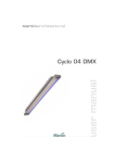
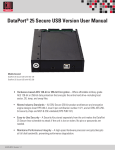
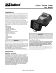
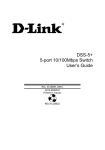
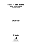
Media Converter Chassis
SNMP Management
User’s Guide
FCC Warning
This equipment has been tested and found to comply with the
regulations for a Class A digital device, pursuant to Part 15 of the
FCC Rules. These limits are designed to provide reasonable protection
against harmful interference when the equipment is operated in a
commercial environment. This equipment generates, uses, and can
radiate radio frequency energy and, if not installed and used in
accordance with this user’s guide, may cause harmful interference to
radio communications. Operation of this equipment in a residential
area is likely to cause harmful interference, in which case the user will
be required to correct the interference at his own expense.
CE Mark Warning
This is a Class A product. In a domestic environment, this product
may cause radio interference, in which case the user may be required
to take adequate measures.
VCCI Warning
TABLE OF CONTENTS
INTRODUCTION.............................................................................. 1
PURPOSE ............................................................................................ 1
OVERVIEW OF THIS USER’S GUIDE .................................................... 1
UNPACKING AND INSTALL......................................................... 3
UNPACKING ....................................................................................... 3
INSTALLING THE MANAGEMENT MODULE ........................................ 3
IDENTIFYING EXTERNAL COMPONENTS.............................. 5
FRONT PANEL .................................................................................... 5
LED INDICATORS .............................................................................. 6
CONFIGURING THE SYSTEM ..................................................... 7
MANAGEMENT THROUGH WEB BROWSER ......................................... 7
CONFIGURE THROUGH TERMINAL EMULATOR/TELNET PROGRAM12
MANAGEMENT SETTING THROUGH TERMINAL EMULATOR ............. 13
APPENDIX....................................................................................... 19
TECHNICAL SPECIFICATIONS ................................................ 21
INTRODUCTION
The SNMP Management Module supports the Media Converter
Chassis to monitor the each Media Converter Module status and to
configure advanced function of the Media Converter Chassis. Through
in-band management via TELNET, Web Browser and SNMP
management utility or the out-band management via RS-232 console
port to monitor/configure the Media Converter Chassis.
The SNMP Management Module supports SNMP protocol to advise
the network manager while the device occur an abnormal status.
Purpose
This manual discusses how to install the SNMP Management Module
to the Media Converter Chassis.
Overview of this User’s Guide
Introduction. Describes the SNMP Management Module and its
features.
Unpacking and Install. Helps you get started with the basic
installation of the SNMP Management Module.
Identifying External Components. Describes the front panel and
LED indicators of the SNMP Management Module.
Configure The Management Module. Helps you how to configure
the SNMP Management Module.
Connecting the SNMP Management Module. Tells how you can
connect the SNMP Management Module to your network.
Technical Specifications. Lists the technical (general, physical and
environmental, performance and Routers settings) specifications of the
SNMP Management Module.
1
UNPACKING AND INSTALL
This chapter provides unpacking and setup information for the SNMP
Management Module.
Unpacking
Open the box of the Management Module and carefully unpack it. The
box should contain the following items:
One SNMP Management Module
One RS232 Cable (9 pin female to 9 pin female)
This User’s Guide
If any item is found missing or damaged, please contact your local
reseller for replacement.
Installing the Management Module
Install the SNMP Management Module into the Media
Converter Chassis.
Connect the SNMP Management Module to the network.
The chassis’s first slot is for the SNMP Management Module as
illustration.
Slide in the management module in the first slot of the chassis system.
3
I DENTIFYING E XTERNAL C OMPONENTS
This section identifies all the major external components of the SNMP
Management Module. The front panel is shown, followed by a
description of each panel feature. The indicator panel is described in
detail in the next chapter.
Front Panel
The figure below shows the front panels of the SNMP Management
Module.
The LED indicators of the SNMP Management Module include Power
On, Power Fail, Fan Fail, MGM, Console and Link/ACT. The
following shows the LED indicators for the Switch along with an
explanation of each indicator.
10/100 Fast Ethernet
LED Indicator Panel
1
Refer to the next section for detailed
information.
Console Port (RS232)
2
POWER ON
LED
Indicator
Copper
Port
POWER FAIL
FAN FAIL
To configure the device through
Terminal Emulation Program via
RS232 serial port.
10/100BASE-TX Twisted-Pair
Port
MGM
CPU WORK
CPU FAIL
CONSOLE
DATA TR ANS FER
ERRO R D ATA
Console
Port
LINK/ACT
LI NK
DATA TR ANS FER
To configure the device through Web Browser or TELNET program
via LAN Ethernet.
5
LED Indicators
There are two powers at the rear and will indicates on the front panel
the status of the power and fan:
Power On: Lights green when the power is inserted.
Power Fail: Lights Amber when the power is inserted and it is fail.
Fan Fail: Lights Amber when the fan is fail to work.
MGM: Blinks green when the device CPU is working and lights
amber when the CPU works fail.
Console: Blinks green when the data is transmitting through console
port and blinks amber when transmitting the wrong data.
Link/Act: Lights green when link to networking Ethernet and blinks
green for activity.
6
C ONFIGURING T HE S YSTEM
This chapter provides network managers and system administrators
with information about how to configure the Media Converter Chassis
via the SNMP Management Module.
The reader of this document should be knowledgeable about network
devices, device configuration, network management, and Internet
browsers. The user is assumed to be a network administrator or
manager with an understanding of network operations.
Management through Web browser
The SNMP Media Converter Chassis is accessible using a Web
browser (IE explorer, Netscape Communications, etc.) to open up the
chassis monitoring system. The
default IP Address for the chassis
system is “192.168.1.1”, and the
default Login name and password
is both “root”.
Main Menu
The Main Menu will show out the
Hardware Revision, BIOS Revision and
Firmware Revision, to set the management
system, click on the left side menu, System
Function and Configuration, in the center screen is the
status screen that appears where you clicked on the left
side menu.
Click on the Media Converter slot and it will appear a
screen for you to monitor or control, depend on what
media converter you are using.
7
1
System Function
There are four items in System Function menu, “Software Reboot,
Factory Reset, Image Update and Configuration Update.
1-2 Software Reboot
Reboot the management module in order to run the new setting
properly.
1-3 Factory Reset
This function is to set the device back to
the default setting in case of the messy
setting.
1-4 Image Update
The section is to set the TFTP Server IP
Address first, and the default address was
set to “192.168.1.2”. The Image File can be updated by uploading the image file from
the TFTP server.
Note: The content of the image file will write the whole firmware of the management module, please be sure
that the image file is correct.
1-5 Configuration Update
The section is explaining how to
upload and download the configure
setting of the module.
The Configuration Upload is to
restore a setting file to the
management module.
The Configuration Download is to
backup the setting from the management module.
8
2
Configuration
There are five items in Configuration menu, General Configuration, System
Configuration, SNMP Configuration, Location Setting and Redundant Backup Setting.
2-1 General Configuration
Hardware revision: noted the version of the Media Converter Chassis.
BIOS revision: noted the version of the BIOS.
Firmware revision: noted the version of the firmware.
Change Password: the changing of the admit password.
Confirm Password: to confirm the setting of admit password.
System Name: to authorize the device system name.
Location: to show the Media Converter Chassis where it is located.
Refresh time: to set the refreshing time of the device through the web.
NOTE: After configuring the system device, need to press the save button to save the
setting.
2-2 General Configuration
MAC Address: will show out the MAC address of the SNMP Management Module.
9
IP Address: to allocate an IP address for the SNMP Management Module, the default
IP is “192.168.1.1”.
Subnet Mask: to set the Subnet Mask, the default is 255.255.255.0”.
Default Gateway: to set the gateway address, the default is “192.168.1.254”.
NOTE: After configuring the system device, need to press the save button to save the
setting.
2-3 SNMP Configuration
Get Community Name: to get the device community name (default = public).
Set Community Name: to set the device community name (default = private).
Trap Community Name: to authorize the device trap community name (default = public).
Trap Host IP Address: to set the trap host IP address (same as monitoring station IP address).
Cold Start trap: to set the trap for rebooting the device (default = enable).
Warm Start trap: to set the trap when the device had been reset (default = enable).
Authentication Fail Trap: to set the warning trap when the community name of the
device and workstation are different (default = enable).
Power Fail Trap: to set the Power Fail Trap (default = enable).
Fan Fail Trap: to set the Fan fail trap (default = enable).
MC Plug-in Trap: to set the trap when a Media Converter Module has been plugged in
(default = enable).
MC Pullout Trap: to set the trap when the Media Converter Module has been pulled
out (default = enable).
10
MC Broken trap: to set the trap when the Media Converter Module was broken (default
= enable).
MC Link up trap: to set the trap when a linking is connected (default = enable).
MC Link down trap: to set the trap when a linking is disconnected (default = enable).
MC Active Slot Xchg trap: to set the trap when there is a redundant function activated
(default = enable).
MC Active Slot Lose trap: to set the trap when the redundant function is fail (default =
enable).
2-4 Location Setting
Allocating each slot’s location in order to remember in where each
slot was connected.
2-5 Redundant Backup Setting
11
The redundant function is to change the master line to the slave line
in case of the linking fails happen.
The Redundant functions were set fixed, the master slot is slot 1(odd
number slot) and the slave slot is slot 2(even number slot), and there
are eight redundant groups in all. The “Act” will indicate what slot
is active.
When the slave slot is active, and we need to transfer again to the
master slot, we need to push on the restart button.
The redundant function depends only on some Smart Media
Converters.
Configure Through Terminal Emulator/TELNET Program
Console and Terminal Emulator program setting
The SNMP Media Converter Chassis can be accessible using a
terminal or terminal emulator attached to the RS232 serial port.
1. Locate correct DB9 serial port cable with female DB9 connector.
2. Attach the DB9 serial port female cable connector to the male
DB9 serial port connector on the chassis system.
3. Attach the other end of the DB9 serial port cable to a remote the
workstation.
4. By default, the Media Converter uses the following serial port
parameter values:
Bits per second
57600
Stop bits
1
Data bits
8
Parity
NONE
Flow Control
NONE
The default Login name and password is both “root”.
12
TELNET program setting
The SNMP Media Converter Chassis can be accessible using
TELNET through LAN.
1.
Run TELNET program.
2.
Enter the IP address “192.168.1.1” (the factory-default IP address
setting).
3.
The default Login name and password is both “root”.
Management Setting Through Terminal Emulator
Main Menu
There are three items in the Main Menu, System Function,
Configuration and SNMP Configuration.
1
System Function
There are three items in System Function menu, “Software Reboot, Factory Reset,
Image Update.
1-1 Software Reboot
After configuring, it needs to reboot the software setting in order to run the device
properly.
13
1-2 Factory Reset
This function is to set the device back to the default setting in case of the messy setting.
1-3 Image Update
The section is to set the TFTP Server IP Address first, and the default address was set to
“192.168.1.2”. The Image File can be updated by uploading the image file from the
TFTP server.
Note: The content of the image file will write the whole firmware of the management
module, please be sure that the image file is correct.
2
Configuration
There are four items in the Configuration menu, “General Configuration, System
Configuration, Media Converter Chassis and Media Converters.
2-1 General Configuration
14
Hardware revision: noted the version of the hardware.
BIOS revision: noted the version of the BIOS.
Firmware revision: noted the version of the firmware.
Change Password: the changing of the admit password.
Confirm Password: to confirm the setting of admit password.
System Name: to authorize the device system name.
Location: to show the device where it is located.
Refresh time: to set the refreshing time of the device through the web.
2-2 System Configuration
MAC Address: will show out the MAC address of the device.
IP Address: to allocate an IP address for the device, the default IP is “192.168.1.1”.
Subnet Mask: to set the Subnet Mask, the default is “255.255.255.0”.
Default Gateway: to set the gateway address, the default is “192.168.1.254”.
NOTE: After configuring the system device, need to press the save button to save the
setting.
2-3 Media Converter Chassis
The screen will show out the power status of the chassis system.
V stands for “yes” and X stands for “No”.
Plug in: indicates if Power 1 or 2 was plugged in or not.
Power Fail: indicates if the Power 1 or 2 is fail or not.
Fan Fail: indicates if the Fan 1 or 2 is fail or not.
15
2-4 Media Converters
Indicates the Link, Duplex mode, Speed and Fail status of each media converter.
2-5 Media Converters Setting
This screen is to set the Device function of LLCF and Link Enable; the Media 1 LLR
function, Auto-Negotiation, Speed, Duplex Mode, Flow Control and Link Enable; the
Media 2 LLR function, Auto-Negotiation, Duplex mode and Link Enable.
The “*” in the screen stands for N/A (not available), and the management module will
detect if the slot has the function in it and will let you set the function exist on the media
converter slot.
Select the slot and press the space bar button to choose which function
Device
LLCF: Link Loss Carry Forward, “on” or “off”.
Enable: to enable the link of the Device, “on” or “off”.
16
to open up.
Media 1
LLR: Link Loss Return, “on” or “off”.
Auto: “A” for Auto-Negotiation or “F” for “forced Mode”.
Speed: to select the speed of the copper port, “10M”, “100M” or “1G”.
Dup: Duplex mode, “F” for Full Duplex or “H” for Half Duplex.
FC: Flow Control, “on” or “off”.
Enable: to enable the link of the Media 1, “on” or “off”.
Media 2
LLR: Link Loss Return, “on” or “off”.
Auto: “A” for Auto-Negotiation or “F” for “forced Mode”.
Dup: Duplex mode, “F” for Full Duplex or “H” for Half Duplex.
Enable: to enable the link of the Media 1, “on” or “off”.
Some of the function can be control only depends on the Smart Media Converter
Modules
2-6 Redundant Backup Setting
The redundant function is to change the master line to the slave line in case of the
linking fails happen.
The Redundant functions were set fixed, the master slot is slot 1(odd number slot) and
the slave slot is slot 2(even number slot), and there are eight redundant groups in all.
The “Act” will indicate what slot is active.
When the slave slot is active, and we need to transfer again to the master slot, push on
the restart button.
The redundant function depends only on some Smart Media Converter Modules.
17
3
SNMP Configuration
Get Community Name: to get the device community name (default = public).
Set Community Name: to set the device community name (default = private).
Trap Community Name: to authorize the device trap community name (default =
public).
Trap Host IP Address: to set the trap host IP address (same as monitoring station IP
address).
Cold Start trap: to set the trap for rebooting the device (default = enable).
Warm Start trap: to set the trap when the device had been reset (default = enable).
Authentication Fail Trap: to set the warning trap when the community name of the
device and workstation are different (default = enable).
Power Fail Trap: to set the Power Fail Trap (default = enable).
Fan Fail Trap: to set the fan fail trap (default = enable).
MC Plug-in Trap: to set the trap when a Media Converter module has been plugged in
(default = enable).
MC Pullout Trap: to set the trap when the Media Converter module has been pulled
out (default = enable).
MC Broken trap: to set the trap when the Media Converter module was broken
(default = enable).
MC Link up trap: to set the trap when a linking is connected (default = enable).
MC Link down trap: to set the trap when a linking is disconnected (default = enable).
MC Active Slot Xchg trap: to set the trap when there is a redundant function activated
(default = enable).
MC Active Slot Lose trap: to set the trap when the redundant function is fail (default =
enable).
18
A PPENDIX
When forgot the password
Boot up the chassis system and press the escape button repetitious
three to four times, then press “root” for login the BIOS setting, some
command key as follow will help: help, ls(list), sysconf (system
configuration), flash, boot
Help: to check the usage of the command list.
Ls: to list out the command key.
Sysconf: to configure or view the system parameter to IIC EEPROM.
Flash: to flash the image file from TFTP server.
Boot: to boot up the system.
The usage will indicate out on the screen when the command key was
input error.
19
T ECHNICAL S PECIFICATIONS
General
IEEE 802.3 10Base-T Ethernet
Applicable
Standards
IEEE 802.3u 100 Base-TX Fast Ethernet
IEEE 802.3x flow control
Protocol
CSMA/CD
Data
Rate
Ethernet: 10Mbps (half duplex), 20Mbps (full duplex)
Transfer
LED Indicators
Cable
Fixed Ports
Fast Ethernet: 100Mbps (half duplex), 200Mbps (full duplex)
Power On, Power Fail, Fan Fail, MGM, Console, Link/ACT
10BASET: 2-pair UTP Cat. 3,4,5; EIA/TIA- 568 100-ohm STP
100BASE-TX: 2-pair UTP Cat. 5; EIA/TIA-568 100-ohm STP
1 x 10/100BASE-TX port
1 x 9 pin RS232 Console port
Power
Consumption
3 watts. (max.)
Temperature
Operating: 0° ~ 50° C, Storage: -10° ~ 70° C
Humidity
Operating: 10% ~ 90%, Storage: 5% ~ 90%
EMI:
FCC Class A, CE Mark Class A, VCCI Class A
21