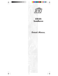
1
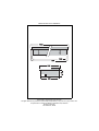
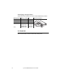
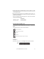
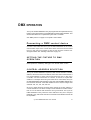
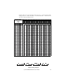
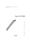
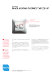
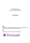
martinarchitectural
user manual
Cyclo 04 DMX Wallwasher
Measurements are in millimeters
1210
1180
1150
290
94
260
© 2003 Martin Professional A/S, Denmark.
All rights reserved. No part of this manual may be reproduced, in any form or by any means, without permission in writing from Martin Professional A/S, Denmark.
Printed in Denmark.
P/N 35000132, Rev B
INTRODUCTION . . . . . . . . . . . . . . . . . . . . . . . . . . . . . . . . . . . . . . . 4
Safety information . . . . . . . . . . . . . . . . . . . . . . . . . . . . . . . . . . . . . . . . . . . . 4
INSTALLATION . . . . . . . . . . . . . . . . . . . . . . . . . . . . . . . . . . . . . . . . 6
Fixture location. . . . . . . . . . . . . . . . . . . . . . . . . . . . . . . . . . . . . . . . . . . . . . . 6
Installing the fixture . . . . . . . . . . . . . . . . . . . . . . . . . . . . . . . . . . . . . . . . . . . 7
AC power . . . . . . . . . . . . . . . . . . . . . . . . . . . . . . . . . . . . . . . . . . . . . . . . . . . 8
Data linking multiple fixtures . . . . . . . . . . . . . . . . . . . . . . . . . . . . . . . . . . . . 9
Fluorescent tubes. . . . . . . . . . . . . . . . . . . . . . . . . . . . . . . . . . . . . . . . . . . . 11
Cleaning . . . . . . . . . . . . . . . . . . . . . . . . . . . . . . . . . . . . . . . . . . . . . . . . . . . 12
STAND-ALONE OPERATION. . . . . . . . . . . . . . . . . . . . . . . . . . . . . . 13
Set the fixture to stand-alone operation . . . . . . . . . . . . . . . . . . . . . . . . . . . 13
Program selection . . . . . . . . . . . . . . . . . . . . . . . . . . . . . . . . . . . . . . . . . . . 13
Master/slave. . . . . . . . . . . . . . . . . . . . . . . . . . . . . . . . . . . . . . . . . . . . . . . . 14
Program examples . . . . . . . . . . . . . . . . . . . . . . . . . . . . . . . . . . . . . . . . . . . 15
DMX OPERATION . . . . . . . . . . . . . . . . . . . . . . . . . . . . . . . . . . . . 17
Connecting a DMX control device . . . . . . . . . . . . . . . . . . . . . . . . . . . . . . . 17
Setting the fixture to DMX operation . . . . . . . . . . . . . . . . . . . . . . . . . . . . . 17
Control address selection. . . . . . . . . . . . . . . . . . . . . . . . . . . . . . . . . . . . . . 17
Intensity control . . . . . . . . . . . . . . . . . . . . . . . . . . . . . . . . . . . . . . . . . . . . . 20
DMX PROTOCOL . . . . . . . . . . . . . . . . . . . . . . . . . . . . . . . . . . . . . 21
SPECIFICATIONS - CYCLO 04 DMX WALLWASHER . . . . . . . . . . . . 22
Cyclo 04 DMX Wallwasher user manual
3
INTRODUCTION
Thank you for selecting the Martin Cyclo 04 DMX Wallwasher. The Cyclo 04
DMX Wallwasher is a recessed fluorescent wallwasher with RGB color
mixing that generates both white and colored light. Suited to a wide range of
retail applications, it also provides an interesting solution for the work
environment by applying dynamic light in recreation areas and conference
rooms.
Cyclo 04 DMX Wallwasher is a fixture based on dimmable fluorescent T5
tubes. The T5 tubes have achieved widespread popularity due to their
design and high efficacy combined with their long lamp life.
Cyclo 04 DMX Wallwasher control and power-cables are through-wired for
easy installation.
The Cyclo 04 DMX Wallwasher offers:
•
•
•
•
Note:
Controllable RGB color-mixing
Full 0-100% intensity control of the red, green, blue and white tubes
Bright output
Precise asymmetrical light and color distribution
It is important to read this manual through before you attempt
to install this product.
SAFETY INFORMATION
Warning!
This product is for professional use only. It is not for household
use.
These products present risks of lethal or severe injury due to fire and heat,
electric shock and falls. Read this manual before powering or installing
these fixtures, follow the safety precautions listed below and observe all
warnings in this manual and on the fixtures. If you have questions about how
to operate these fixtures safely, please contact your Martin dealer or call the
Martin 24-hour service hotline at +45 70 200 201.
P rot ecti on fr om el ect ric sh ock
• Disconnect the fixtures from AC power before removing or installing a lamp,
fuses, or any part, and when not in use.
4
Cyclo 04 DMX Wallwasher user manual
• Always ground (earth) the fixtures electrically.
• Use only a source of AC power that complies with local building and
electrical codes and has both overload and ground-fault protection.
• Do not expose the fixtures to rain or moisture.
• Refer all service to a Martin service technician.
Protection from burns and fire
• Provide a minimum clearance of 0.1 meters (4 inches) around the fixture.
• Do not modify the fixture or install other than genuine Martin parts.
• Do not operate the fixture if the ambient temperature (Ta) exceeds 40° C
(104° F).
Protection from injury due to fall s
• Verify that all external covers and rigging hardware are securely fastened
• Block access below the work area whenever installing or removing the
fixture.
Cyclo 04 DMX Wallwasher user manual
5
INSTALLATION
This section describes in general terms how to install the fixture and
connect it to AC and dimmer power. These procedures shall be performed
by qualified professionals.
Mains
200-250V AC
50/60 Hz
Category 5 DMX network
DMX control device
FIXTURE LOCATION
The fixture can be installed in a
ceiling space of 1200 x 275 mm (+/15
mm).
In
US/Imperial
measurements this is 47 x 11 in. (+/0.5 in.). The installation space should
have a depth of at least 120 mm (4.7
in.)
The fixture should be installed a
distance away from the wall that is at
least 1/3rd of the height of the wall.
6
Cyclo 04 DMX Wallwasher user manual
1/3h
h
INSTALLING THE FIXTURE
To install the fixture:
1 Pull the tube cover off.
2 Slide the reflector towards the tubes to unlock it.
3 Pull the reflector out.
4 Insert the fixture into the ceiling.
Cyclo 04 DMX Wallwasher user manual
7
5 Four metal stays that hold the product in position are provided. Insert a stay
into each of the four holes on the sides of the fixture and screw it into place.:
6 Connect the AC power and dimmer control wiring (as described in the
following sections) before replacing the reflector or tube cover.
AC POWER
Maximum power usage data for the Cyclo 04 DMX Wallwasher is supplied in
“Specifications - Cyclo 04 DMX Wallwasher” on page 22.
Warning:
Cyclo 04 DMX Wallwasher fixtures incorporate four electronic
ballasts that “leak” a total of between 0.8-4mA of power.
Because of this we recommend connecting a maximum of seven
Cyclo 04 DMX Wallwasher fixtures per phase on a 30mA HPFI
circuit breaker.
A normal 30 mA HPFI circuit breaker normally trips because of a
current fault or leakage of approximately 20mA. It is important
that the installation is carried out correctly in order to avoid
unintentional tripping of the circuit breaker.
Many installations use common neutral leads in branch circuit
distribution boxes. It is important that the neutral lead in the
cable is connected to the same HPFI circuit breaker, that it is
not connected to the neutral leads from other HPFI circuit
breakers. The neutral lead must be only associated with that
specific circuit breaker. Additionally it is important that the
fixtures are connected correctly to the ground (earth) to ensure
that the power leakage is able to run off.
8
Cyclo 04 DMX Wallwasher user manual
You can power Cyclo 04 DMX Wallwasher fixtures by wiring them in series.
The internal wiring of the fixtures carries AC power through the fixture. Male
and female Ensto connectors are provided at opposite ends of the fixture for
input and output cables. AC power is connected into the fixture via the
female EnstoNet Installation System socket and out (to the next fixture) via
the male socket at the other end of the fixture.
Power cabling and connectors are not supplied with the Cyclo 04 DMX
Wallwasher but cabling and connectors in a range of configurations can be
ordered from your local Ensto distributor, or the following connectors and
cables are available from your Martin dealer:
ENSTO 3 pole 16A/250V male connector . . . . . . . . . . . . . . . . . . . . . . . . . . . P/N 05347202
ENSTO 3 pole 16A/250V female connector. . . . . . . . . . . . . . . . . . . . . . . . . . P/N 05327202
ENSTO male/female cable (15 cm/5.9in.) . . . . . . . . . . . . . . . . . . . . . . . . . . . P/N 11501019
Be sure to refer and comply with local standards. Some common AC cable
configurations are:
Wire (EU)
Wire (US)
Pin
Marking
brown
black
live
“L” or “1”
blue
white
neutral
“N”
yellow/green
green
ground
Cyclo 04 DMX Wallwasher fixtures can be powered in series with other
Cyclo 04 DMX Wallwasher fixtures of the same type. When doing this be
sure to use a power cable that is able to handle the 0.56A that is drawn by
each fixture in the series.
DATA LINKING MULTIPLE FIXTURES
You need to create a data link if you are going to be:
Cyclo 04 DMX Wallwasher user manual
9
• Operating multiple Cyclo 04 DMX Wallwashers in a synchronous way using
the stand-alone functionality
• Controlling more than one fixture via a DMX control device
Cr eati ng a data l in k
The data transmission rate (250 kbits/s) used by DMX512 requires the
selection of a cable which does not significantly distort the signal or give rise
to spurious signal reflections. Cables intended for use with audio systems
(microphone cables), while having the convenience of flexibility, availability
and relative low cost, are NOT suitable for use with DMX512 because of
their high capacitance and incorrect characteristic impedance; at DMX512
data rates this will give rise to bit time distortion and signal
reflections/overshoot.
Cabling systems shall provide a balanced, nominal 120 ohm terminated
transmission line, and be made of cables with a characteristic impedance in
the range 100-120 ohms. The following cabling accessories can be ordered
from your Martin dealer:
CAT5 network cables - 2 m (6.5 ft) x 50 pieces. . . . . . . . . . . . . . . . . . . . . . . .P/N 91611044
CAT5 network cables - 5 m (16.4 ft) x 30 pieces. . . . . . . . . . . . . . . . . . . . . . .P/N 91611045
CAT5 network cables - 10 m (32.8 ft) x 15 pieces. . . . . . . . . . . . . . . . . . . . . .P/N 91611045
CAT5 network cable - 0.25 m (10 in.) x 1 piece . . . . . . . . . . . . . . . . . . . . . . .P/N 11840088
Termination Plug RJ-45 . . . . . . . . . . . . . . . . . . . . . . . . . . . . . . . . . . . . . . . . . .P/N 91613028
Note:
Mixing cables of different impedances and other characteristics
not isolated by buffers or other processing devices may affect
system reliability.
Always use solid or stranded shielded-twisted pair/foiled twisted pair
(STP/FTP), 100 or 120 ohm cables that conform to ISO IEC 11801 category
5 or higher with RJ-45 connectors wired as follows
Pair
Wire #
Color
Function
DMX512 Pin
Pair 2
1
white / orange
data 1 +
DMX512 Pin 3
2
orange
data 1 -
DMX512 Pin 2
Pair 3
3
white / green
data 2 +
DMX512 Pin 5
4
green
data 2 -
DMX512 Pin 4
Pair 1
5
blue
Not assigned
6
white / blue
Not assigned
7
white / brown
Signal Common (0 v)
DMX512 Pin 1
8
brown
Signal Common (0 v)
DMX512 Pin 1
Pair 4
Shield
10
drain
Cyclo 04 DMX Wallwasher user manual
The minimum wire size is 0.2 mm (24 AWG) for runs up to 300 meters (1000
ft.) and 0.322 mm (26 AWG) for runs up 500 meters (1640 ft.). Your Martin
dealer can supply the right cable in various lengths.
The: RJ-45 sockets in the Cyclo 04 DMX Wallwasher are wired as follows pins 7 & 8 to ground, pin 2 to signal - (cold), and pin 1 to signal + (hot).
Cr e a ti n g t h e d at a li n k
1 Connect the RJ-45 connector on the Cyclo 04 DMX Wallwasher to the RJ45 connector on the next Cyclo 04 DMX Wallwasher.
2 Continue connecting fixtures output to input. Up to 32 devices may be
connected on a serial link.
3 Terminate the link by inserting a an RJ-45 termination plug into the RJ-45
data output of the last fixture.
Warning
If you are using Stand-Alone programs (see “Stand-alone
operation” on page 13) on multiple fixtures on a data link and
you experience random “flicker” or other unexplained control
problems, insert a female termination plug (P/N 91613018) into
the IN socket of the first fixture.
FLUORESCENT TUBES
Removi ng tu bes
To remove a tube, pull the lamp
cover off, grasp both ends of the
tube and rotate it until it you are
able to lift an end free.
You may need to remove the
outside tubes in order to access
tubes in the middle of the
mount.
It is advisable to replace all the
tubes simultaneously.
Bu r ni ng i n new tub e s
In order to obtain the full life time, new fluorescent tubes must be burned in
for 100 hundred hours at full power.
Cyclo 04 DMX Wallwasher user manual
11
I dentifying tube positi ons
Tube positions are identified in the Cyclo 04 DMX Wallwasher as follows:
Marking in fixture Marking on tube Color
R
OSRAM 28/60
Red
G
OSRAM 28/66
Green
B
OSRAM 28/67
Blue
Reference illustration
R
None
OSRAM 28/827
OSRAM 28/840
OSRAM 28/860
G
B
2700K white
4000K white
6000K white
CLEANING
We recommend that you clean the fixture with a damp cloth.
12
Cyclo 04 DMX Wallwasher user manual
STAND-ALONE OPERATION
In stand-alone mode, individual Cyclo 04 DMX Wallwasher fixtures can run
a set of pre-programmed shows without an external controller. Multiple
Cyclo 04 DMX Wallwasher fixtures can also be linked together and scene
changes on all fixtures can be synchronously triggered by a “master” fixture.
SET THE FIXTURE TO STAND-ALONE
OPERATION
Stand-alone operation is enabled by setting pin 10 on the DIP switch to ON.
DIP-switch settings in stand-alone mode
Pin
Function
1
White
2
Red
3
Green
4
Blue
5&6
Program speed
Pin 6
Pin 5
Speed
Off
Off
Full speed (1 sec. pr. state)
Off
On
1/5 speed (5 sec. pr. state)
On
Off
1/10 speed (10 sec. pr. state)
On
On
1/30 speed (30 sec. pr. state)
7
OFF = crossfade@0%, ON = crossfade@50%
8
OFF = Run program, ON = Pause program
9
OFF = Master, ON = Slave
10
ON = Stand Alone mode.
Table 1. DIP-switch settings in stand-alone mode
PROGRAM SELECTION
DIP-switch 1 to 4 each controls a single tube, and these DIP-switches can
be combined to activate more than one tube. If DIP-switch 7 is set to OFF
Cyclo 04 DMX Wallwasher user manual
13
(crossfade@0%) then the tube will turn fully off before it fades in (or
alternatively when more tubes are selected, the next tube will fade in).
If DIP-switch 7 is set to ON (crossfade@50%) the tube will only fade down to
50% before it fades to full again (or alternatively when more tubes are
selected, the next tube will fade in when the first reach 100% and they "will
meet" at 50%)
MASTER/SLAVE
When a fixture is set to master (DIP-switch pin 9 is off), it will transmit a
synchronizing signal to slave fixtures over the data link whenever it changes
to the next scene. Slave fixtures (DIP-switch pin 9 is set on) only change
scenes when they receive synchronization signals from the master fixture.
The slave program will be as set by its DIP-switch, so to have a master and
a slave run the same program, their DIP-switch settings have to be the same
(apart from the Master/Slave setting).
The synchronization signal is the same as used by other Mar tin
Architectural products, so this enables the stand-alone functionality to be
used with a range of other Martin products.
To have a single fixture run alone, it must be set to master. Slave fixtures
must not be connected to more than one master.
Advanced mast er/slave
To make more advanced schemes, it is important to understand how scenes
are numbered. The scene pattern is always established in the sequence
white to red to green to blue. This means that if white is enabled, it will
always be placed first in the program. When crossfade@0% is selected,
e a c h c o l o r t a ke s u p t wo s c e n e s ( fa d e i n a n d fa d e o u t ) . W h e n
crossfade@50% is selected, each color takes up one scene (fade in only).
Scene numbering always starts at 0, and a maximum number of 8 scenes (0
- 7) can be set, with all colors enabled and crossfade@0%.
Each scene can be seen as a translation from one output to another, this
translation is called a fade, and the time of the fade is set by the speed
setting of the DIP-switch. When a fixture is in slave mode, each new fade is
initiated by a synchronization signal received from the master. When the
slave receives a synchronization signal, and initiates a fade, it will not act on
new synchronization pulses, until the fade is complete.
If a slave fixture has:
14
Cyclo 04 DMX Wallwasher user manual
1 Fewer scenes than the master fixture, it will run these in a cycle
continuously, until the master fixture signals that the program should start
from the beginning again.
2 More scenes than the master, then the additional scenes will never run,
because the program will reset to the first scene when the master starts its
program from the beginning.
Here is an example of what will happen when a slave fixture has fewer
scenes than the master fixture:
Scene pattern
Master with 7 scenes
01234560123456012...
Slave with 3 scenes
01201200120120012...
PROGRAM EXAMPLES
In all programs in these examples each scene lasts for 1 second at full
speed.
The following symbols are used in program diagrams:
Tube turned fully off
Tube turned on at min level
Fade in
Fade out
Fade to 50% and back to 100% in one scene
Exampl e 1
DIP-switch 7 is set to OFF = crossfade@0% and only white is selected:
White
Scene
0
1
0
1
0
1
0
1
0
Cyclo 04 DMX Wallwasher user manual
1
0
1
15
Example 2
DIP-switch 7 is set to OFF = crossfade@0% and white and red is selected:
White
Red
Scene
0
1
2
3
0
1
2
3
0
1
2
3
Example 3
DIP-switch 7 is set to ON = crossfade@50% and only white is selected:
White
Scene
0
0
0
0
0
0
0
0
0
0
0
0
Example 4
DIP-switch 7 is set to ON = crossfade@50% and white and red is selected:
White
Red
Scene
0
1
2
3
0
1
2
3
0
1
2
3
Example 5
The rainbow effect is achieved by selecting, red, green, blue and DIP-switch
7 is set to ON = crossfade@50%.
Red
Green
Blue
Scene
16
0
1
2
0
1
2
0
1
2
0
Cyclo 04 DMX Wallwasher user manual
1
2
DMX OPERATION
The Cyclo 04 DMX Wallwasher may be programmed and operated with any
lighting control device that is compatible with the USITT DMX standard. This
section describes how to operate the system with a controller.
See “DMX protocol” on page 21 for specific control values.
Connecting a DMX control device
Connect a data cable from the Cyclo 04 DMX Wallwasher to the control
device’s data output. If the control device does not have an RJ-45 socket
then you may need to purchase or wire an XLR-to-RJ45 converter. For
wiring information see “Creating a data link” on page 10.
SETTING THE FIXTURE TO DMX
OPERATION
DMX operation is enabled by setting pin 10 on the DIP switch to OFF.
CONTROL ADDRESS SELECTION
The Cyclo 04 DMX Wallwasher requires 4 DMX control channels. The DMX
address, also known as the start channel, is the first control channel used. It
is a logical address to which control instructions are sent. In this way a
controller, can send instructions to a fixture, or fixtures, at a particular
address. For example when using four channels of control data, the Cyclo
04 DMX Wallwasher reads the data on the start channel (DMX address) and
the next three channels. If the DMX address is set to 100, the Imager uses
channels 100, 101, 102, 103, and 104.
Be sure to allow adequate channels when setting the control address. If
control channels for one fixture overlap control channels for another fixture,
then one of the fixtures will receive the wrong commands. Two Cyclo 04
DMX Wallwashers may share the same address if they are to respond
identically. They will receive the same commands and individual control will
be impossible.
Cyclo 04 DMX Wallwasher user manual
17
The default factory set control address is ‘1’.
Setting the DMX address
1 Select an address for the fixture on your controller. Look up the DIP switch
setting for the address in the following table.
2 Set pins 1 through 9 ON (1) or OFF (0) as listed in the table.
3 Ensure that pin 10 is set to OFF.
18
Cyclo 04 DMX Wallwasher user manual
Find the address in the table. Read the settings for pins 1 - 5 to the left and read the
settings for pins 6 - 9 above the address. “0” means OFF and “1” means ON. Pin
10 is always OFF for DMX operation.
DIP switch Setting
#5
0
0
0
0
0
0
0
0
0
0
0
0
0
0
0
0
1
1
1
1
1
1
1
1
1
1
1
1
1
1
1
1
0
0
0
0
0
0
0
1
0
0
1
0
0
0
1
1
0
1
0
0
0
1
0
1
0
1
1
0
0
1
1
1
1
0
0
0
1
0
0
1
1
0
1
0
1
0
1
1
1
1
0
0
1
1
0
1
1
1
1
0
1
1
1
1
1
2
3
4
5
6
7
8
9
10
11
12
13
14
15
16
17
18
19
20
21
22
23
24
25
26
27
28
29
30
31
32
33
34
35
36
37
38
39
40
41
42
43
44
45
46
47
48
49
50
51
52
53
54
55
56
57
58
59
60
61
62
63
64
65
66
67
68
69
70
71
72
73
74
75
76
77
78
79
80
81
82
83
84
85
86
87
88
89
90
91
92
93
94
95
96
97
98
99
100
101
102
103
104
105
106
107
108
109
110
111
112
113
114
115
116
117
118
119
120
121
122
123
124
125
126
127
128
129
130
131
132
133
134
135
136
137
138
139
140
141
142
143
144
145
146
147
148
149
150
151
152
153
154
155
156
157
158
159
160
161
162
163
164
165
166
167
168
169
170
171
172
173
174
175
176
177
178
179
180
181
182
183
184
185
186
187
188
189
190
191
192
193
194
195
196
197
198
199
200
201
202
203
204
205
206
207
208
209
210
211
212
213
214
215
216
217
218
219
220
221
222
223
224
225
226
227
228
229
230
231
232
233
234
235
236
237
238
239
240
241
242
243
244
245
246
247
248
249
250
251
252
253
254
255
256
257
258
259
260
261
262
263
264
265
266
267
268
269
270
271
272
273
274
275
276
277
278
279
280
281
282
283
284
285
286
287
288
289
290
291
292
293
294
295
296
297
298
299
300
301
302
303
304
305
306
307
308
309
310
311
312
313
314
315
316
317
318
319
320
321
322
323
324
325
326
327
328
329
330
331
332
333
334
335
336
337
338
339
340
341
342
343
344
345
346
347
348
349
350
351
352
353
354
355
356
357
358
359
360
361
362
363
364
365
366
367
368
369
370
371
372
373
374
375
376
377
378
379
380
381
382
383
384
385
386
387
388
389
390
391
392
393
394
395
396
397
398
399
400
401
402
403
404
405
406
407
408
409
410
411
412
413
414
415
416
417
418
419
420
421
422
423
424
425
426
427
428
429
430
431
432
433
434
435
436
437
438
439
440
441
442
443
444
445
446
447
448
449
450
451
452
453
454
455
456
457
458
459
460
461
462
463
464
465
466
467
468
469
470
471
472
473
474
475
476
477
478
479
480
481
482
483
484
485
486
487
488
489
490
491
492
493
494
495
496
497
498
499
500
501
502
503
504
505
506
507
508
509
510
511
Channel 2
Channel 14
1 2 3 4 5 6 7 8 9 10
Channel 46
ON
1 2 3 4 5 6 7 8 9 10
ON
1 2 3 4 5 6 7 8 9 10
ON
Table 2: DIP switch address settings
ON
#1
0
1
0
1
0
1
0
1
0
1
0
1
0
1
0
1
0
1
0
1
0
1
0
1
0
1
0
1
0
1
0
1
0 = OFF
1 = ON
#2 #3 #4
0
0
0
0
0
0
1
0
0
1
0
0
0
1
0
0
1
0
1
1
0
1
1
0
0
0
1
0
0
1
1
0
1
1
0
1
0
1
1
0
1
1
1
1
1
1
1
1
0
0
0
0
0
0
1
0
0
1
0
0
0
1
0
0
1
0
1
1
0
1
1
0
0
0
1
0
0
1
1
0
1
1
0
1
0
1
1
0
1
1
1
1
1
1
1
1
#9
#8
#7
#6
1 2 3 4 5 6 7 8 9 10
Channel 100
Address Setting Examples
Cyclo 04 DMX Wallwasher user manual
19
INTENSITY CONTROL
The intensity of the individual colors can be set from minimum to maximum
on channels 1 to 4.
20
Cyclo 04 DMX Wallwasher user manual
DMX PROTOCOL
Start code = 0
Channel
Value
Percent
Function
0-2
3-252
253-255
0
1 - 99
100
White intensity
Tube off
Intensity 1→100%
Intensity 100%
0-2
3-252
253-255
0
1 - 99
100
Red intensity
Tube off
Intensity 1→100%
Intensity 100%
0-2
3-252
253-255
0
1 - 99
100
Green intensity
Tube off
Intensity 1→100%
Intensity 100%
0-2
3-252
253-255
0
1 - 99
100
Blue intensity
Tube off
Intensity 1→100%
Intensity 100%
1
2
3
4
Cyclo 04 DMX Wallwasher user manual
21
SPECIFICATIONS - CYCLO 04
DMX WALLWASHER
PHYSICAL
L x W x H. . . . . . . . . . . . . . . . . . . . . . . . . . . . . . 1210 x 290 x 94 mm (47.6 x 11.4 x 3.7 in.)
Weight. . . . . . . . . . . . . . . . . . . . . . . . . . . . . . . . . . . . . . . . . . . . . . . . . . . . . . . . . 9 kg (20 lbs)
INSTALLATION
Installation space (L x W) . . . . . . . . . . . . 1200 x 275 mm +/-15 mm (47 x 11 in. +/-0.5 in.)
Installation space depth . . . . . . . . . . . . . . . . . . . . . . . . . . . . . . . . . . . . . . . . 120 mm (4.7 in.)
Minimum free space around fixture when installed . . . . . . . . . . . . . . . . . . . . 25 mm (1 inch)
SOURCE
Approved lamp type . . . . . . . . . . . . . . . . . . . . . . . . . . . . . . . . OSRAM T5 FH 28 watt tubes
Light source . . . . . . . . . . . . . . . . . . . . . . . . . . . . . . . . . . . . . . . . . . . . . . . .T5 tubes (3x28W)
POWER
AC power . . . . . . . . . . . . . . . . . . . . . . . . . . . . . . . . . . . . . . . . . . . .198 V - 254 V, 50 / 60 Hz
Dimmer control . . . . . . . . . . . . . . . . . . . . . . . . . . . . . . . . . . . . . . . . . . . . . . . , 1-10V control
Maximum power and current @ 230 V / 50 Hz . . . . . . . . . . . . . . . . . . . . .0.56 A / 128 watts
THERMAL
Maximum ambient temperature (Ta) . . . . . . . . . . . . . . . . . . . . . . . . . . . . . . . 40° C (104° F)
DYNAMIC EFFECTS
Dimmable tubes . . . . . . . . . . . . . . . . . . . . . . . . . . . . . . . . . . . . . . Red, green, blue and white
Independent dimming of each tube via DMX control device
CONTROL AND PROGRAMMING
Control options . . . . . . . . . . . . . . . . . . . . . . . . . . . . . . . .DMX512, stand alone, master/slave
Receiver . . . . . . . . . . . . . . . . . . . . . . . . . . . . . . . . . . . . . . . . . . . . . . . . . . . . . . . . . . . RS-485
Setting and addressing . . . . . . . . . . . . . . . . . . . . . . . . . . . . . . . . . . . . . . . . . . . . . DIP switch
Data input . . . . . . . . . . . . . . . . . . . . . . . . . . . . . . . . . . . . . . . . . . . . . . . . . . . . . . . . . . . .RJ-45
Data output . . . . . . . . . . . . . . . . . . . . . . . . . . . . . . . . . . . . . . . . . . . . . . . . . . . . . . . . . . .RJ-45
DMX channels . . . . . . . . . . . . . . . . . . . . . . . . . . . . . . . . . . . . . . . . . . . . . . . . . . . . . . . . . . . 4
ORDERING INFORMATION
Cyclo 04 DMX Wallwasher . . . . . . . . . . . . . . . . . . . . . . . . . . . . . . . . . . . . . . .P/N 90550035
INCLUDED ITEMS
Lamp. . . . . . . . . . . . . . . . . . . . . . . . . . . . . . . . . . . . . . . . . . . . .OSRAM T5 FH28W/60 (red)
Lamp. . . . . . . . . . . . . . . . . . . . . . . . . . . . . . . . . . . . . . . . . . OSRAM T5 FH 28W/66 (green)
Lamp. . . . . . . . . . . . . . . . . . . . . . . . . . . . . . . . . . . . . . . . . . . .OSRAM T5 FH28W/67 (blue)
Lamp. . . . . . . . . . . . . . . . . . . . . . . . . . . . . . . . . . . . . . . . . .OSRAM T5 FH28W/840 (white)
User manual
22
Cyclo 04 DMX Wallwasher user manual
ACCESSORIES
Termination Plug RJ-45. . . . . . . . . . . . . . . . . . . . . . . . . . . . . . . . . . . . . . . . . . P/N 91613028
XLR male to RJ-45 converter . . . . . . . . . . . . . . . . . . . . . . . . . . . . . . . . . . . . . P/N 11840087
XLR female to RJ-45 connector . . . . . . . . . . . . . . . . . . . . . . . . . . . . . . . . . . . P/N 11840086
CAT5 network cables - 2 m (6.5 ft) x 50 pieces . . . . . . . . . . . . . . . . . . . . . . . P/N 91611044
CAT5 network cables - 5 m (16.4 ft) x 30 pieces . . . . . . . . . . . . . . . . . . . . . . P/N 91611045
CAT5 network cables - 10 m (32.8 ft) x 15 pieces . . . . . . . . . . . . . . . . . . . . . P/N 91611045
CAT5 network cable - 0.25 m (10 in.) x 1 piece . . . . . . . . . . . . . . . . . . . . . . . P/N 11840088
ENSTO 3 pole 16A/250V male connector . . . . . . . . . . . . . . . . . . . . . . . . . . . P/N 05347202
ENSTO 3 pole 16A/250V female connector. . . . . . . . . . . . . . . . . . . . . . . . . . P/N 05327202
ENSTO male/female cable (15 cm/5.9in.) . . . . . . . . . . . . . . . . . . . . . . . . . . . P/N 11501019
Cyclo 04 DMX Wallwasher user manual
23
www.martin-architectural.com • Olof Palmes Allé 18 • 8200 Aarhus N • Denmark
Tel: +45 8740 0000 • Fax +45 8740 0010