1
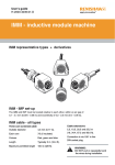
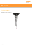
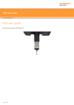
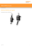
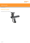
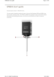
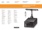
MRS installation and user's guide http://www.renishaw.com MRS installation and user's guide Documentation part number H-1000-5088-06-A Issued 12 2014 1 MRS installation and user's guide http://www.renishaw.com General information © 2001 2014 Renishaw plc. All rights reserved. This document may not be copied or reproduced in whole or in part, or transferred to any other media or language, by any means, without the prior written permission of Renishaw. The publication of material within this document does not imply freedom from the patent rights of Renishaw plc. Disclaimer RENISHAW HAS MADE CONSIDERABLE EFFORTS TO ENSURE THE CONTENT OF THIS DOCUMENT IS CORRECT AT THE DATE OF PUBLICATION BUT MAKES NO WARRANTIES OR REPRESENTATIONS REGARDING THE CONTENT. RENISHAW EXCLUDES LIABILITY, HOWSOEVER ARISING, FOR ANY INACCURACIES IN THIS DOCUMENT. Trademarks RENISHAW® and the probe emblem used in the RENISHAW logo are registered trademarks of Renishaw plc in the UK and other countries. apply innovation is a trademark of Renishaw plc. All brand names and product names used in this document are trade names, service marks, trademarks, or registered trademarks of their respective owners. Windows XP, Windows 2000, Vista and Windows 7 are registered trade names of the Microsoft Corporation. All trademarks and trade names are acknowledged. WEEE The use of this symbol on Renishaw products and/or accompanying documentation indicates that the product should not be mixed with the general household waste upon disposal. It is the responsibility of the end user to dispose of this product at a designated collection point for waste electrical and electronic equipment (WEEE) to enable reuse or recycling. Correct disposal of this product will help save valuable resources and prevent potential negative effects on the environment. For more information, please contact your local waste disposal service or Renishaw distributor. Warranty Renishaw plc warrants its equipment for a limited period (as set out in our Standard Terms and Conditions of Sale) provided that it is installed exactly as defined in associated Renishaw documentation. Prior consent must be obtained from Renishaw if non-Renishaw equipment (e.g. interfaces and/or cabling) is to be used or substituted. Failure to comply with this will invalidate the Renishaw warranty. Claims under warranty must be made from authorised service centres only, which may be advised by the supplier or distributor. Issued 12 2014 2 MRS installation and user's guide http://www.renishaw.com Care of equipment Renishaw probes and associated systems are precision tools used for obtaining precise measurements and must therefore be treated with care. Changes to Renishaw products Renishaw reserves the right to improve, change or modify its hardware or software without incurring any obligations to make changes to Renishaw equipment previously sold. Issued 12 2014 3 MRS installation and user's guide http://www.renishaw.com References and associated documents For instructions on fitting, datuming and operation of the ACR3, FCR25, SCP80, SCR600, RCP rack and port assemblies, please refer to the following documents: Title Document number Relevant topics Installation and user's guide: ACR3 H-1000-5087 ACR3 autochange rack Installation and user's guide: SP25M system H-1000-5104 FCR25 and FRC25 TC Installation and integration guide: SP80 H-1000-5212 SCP80 stylus change port User's guide: SP80 H-1000-5213 SCP80 stylus change port Installation leaflet: SCP600 H-1000-5097 SCP600 stylus change port User's guide: REVO H-1000-5129 RCP, RCP TC-2, SFCP, SFA, TDA and REVO Issued 06 2015 4 MRS installation and user's guide http://www.renishaw.com System description The MRS is designed to provide a flexible platform for Renishaw probe and stylus changing racks. The system comprises of an extruded aluminium rail mounted to the CMM table by two leg assemblies. It is available in rail lengths of 400 mm (15.75 in), 600 mm (23.62 in), 900 mm (35.43 in) and 1000 mm (39.37 in) to suit a variety of port and rack changing requirements. Custom rail lengths are also available. The MRS can be placed at different heights from the CMM table by using multiples of the MRS standard and heavy duty legs, thus allowing clearance for long styli and extension bars. The interconnecting MRS legs supplied (four per kit) are each 125 mm (4.92 in) long. A maximum recommended leg length of 500 mm (19.69 in) can be achieved by purchasing additional legs. These are available in either 62.5 mm (2.46 in) or 125 mm (4.92 in) lengths. The combined MRS rack and leg assembly is mounted on the CMM table via two MRS feet (see item 7 in illustration below). These extend the overall height by 35 mm allowing a maximum clearance of 535 mm between the CMM table and the underside of the MRS rail. Modular rack system compatibility The MRS is compatible with the following Renishaw port and change rack systems: ACR3 (autochange rack) RCP TC-2 (thermally controlled REVO change port) FCR25 (flexible change rack) RCP2 (change port for RSH stylus holders) FRC25 TC (thermally controlled flexible change rack) SFA and SFCP (for REVO surface finish probe) SCP80 (stylus change port for SP80) TDA (REVO tip datum artefact) SCP600 (stylus change port for SP600, SP600M and SP600Q) Key 1. 2. 3. 4. 5. 6. 7. 8. 9. Issued 12 2014 MRS rail Port or rack Fixing screw MRS leg Leg to foot adaptor Grubscrews MRS foot Step-back adaptor M8 screw 5 MRS installation and user's guide http://www.renishaw.com MRS heavy duty legs Where heavier rack systems or longer styli configurations are used, such as multiple SCP80s or RCP TC-2s, the MRS system can be upgraded by using optional heavy-duty legs that are 60 mm (2.36 in) in diameter and 350 mm (13.78 in) long. These legs are mounted to the CMM table beneath the standard legs and feet. Key 1. 2. 3. 4. 5. 6. 7. Heavy-duty leg Leg to foot adaptor and washer Footplate Standard MRS leg Leg to foot adaptor M8 or M10 screw and washer Standard MRS foot NOTE: The MRS heavy-duty leg kit part number is A-4192-0020 and comprises one heavy-duty leg assembly. Two kits are required for each MRS installation. MRS adjustable footplates By using optional MRS adjustable footplates, the MRS rail can be set back on the CMM table to maximise the available working volume of the machine. The MRS adjustable footplates can be used with both standard and heavy-duty leg arrangements. Adjustment is set by the footplate bolt hole spacing in increments of 25 mm, 50 mm, 75 mm, 100 mm (0.98 in, 1.97 in, 2.95 in, 3.94 in). Issued 12 2014 6 MRS installation and user's guide http://www.renishaw.com NOTE: The MRS adjustable footplate kit part number is A-4192-0702 and comprises two footplates. One kit is required for each MRS installation. Step back adaptor Step back adaptors can be used to set the MRS rail back on the CMM bed to maximise the available working volume of the machine. A step back spacer is available to allow the RCP TC-2 to fit in front of the MRS leg. Issued 12 2014 7 MRS installation and user's guide http://www.renishaw.com Key 1. 2. 3. 4. Issued 12 2014 Standard MRS leg MRS rail Step back adaptor T-nut and screw 8 MRS installation and user's guide http://www.renishaw.com Fitting the MRS feet Fitting the MRS feet to the CMM The MRS feet should be fitted to the CMM table along either the X or Y axis. The following procedure details the installation. 1. Place the MRS foot (item 3 in illustration below) on the CMM table and position it over the chosen mounting hole. The feet do not require any rotational alignment. 2. Two pairs of screws are supplied with the MRS*, one pair of M10 and one pair of M8 (item 1) with washers (item 2). The appropriate screw size should be used to secure the MRS foot to the CMM table. 3. Tighten the bolt using the hexagonal key supplied. 4. Fit the second foot at the appropriate distance along the chosen axis following steps 1 to 3 above. * If the bolts supplied do not fit the CMM table then suitable alternatives should be found. Key 1. Screw 2. Washer (optional) 3. MRS foot Aligning the MRS feet to a CMM axis To ease installation of the rail to the MRS it is recommended that the MRS feet be aligned to a CMM axis. The procedure is as follows: 1. Measure the internal diameter of one of the MRS feet and make this a datum. 2. Measure the internal diameter of the other MRS foot. 3. Calculate the out-of-position angle of the MRS feet using the following formula: If the angle exceeds 0.5° then adjustment is necessary. Changing the relative foot position is achieved by releasing the bolt that holds the foot to the CMM table, moving the foot and then re-tightening the bolt. Steps 1 to 3 above should then be repeated. Issued 12 2014 9 MRS installation and user's guide http://www.renishaw.com Fitting standard legs to the MRS Two options are available for mounting the legs to the rail of the MRS. The direct fitting option allows legs to be attached onto the underside of the rail. Using the step-back adaptor option allows legs to be fitted to the back of the rail and provides more measuring volume. Recommended procedures for these two options are detailed in this section. WARNING: The MRS rail is shipped without the plastic end-caps fitted. Therefore there is a possibility that sharp edges could be exposed. Direct fitting of legs to the MRS rack The method for directly fitting legs to the MRS rack is as follows: 1. Referring to the illustration below, slide the T-nuts (item 1) into the T-nut slot in the underside of the MRS rail (item 2), one Tnut is required for each leg. Ensure that the longer portion of the T-nut is facing away from the end of the rail. The appropriate number of T-nuts should be placed into the slot for the change port or rack device to be used. 2. Once all the T-nuts have been installed in the correct orientation, the plastic end caps (item 3) can be pressed into the rail. 3. Referring to the image below, connect the required number of legs and / or leg extensions (item 1) (up to a maximum of four per leg assembly) and hand-tighten. The MRS leg-to-foot adaptors (item 2) can now be screwed into the bottom of each leg and hand-tightened. 4. Place the MRS legs into the MRS feet (item 3) on the CMM table and adjust the three grubscrews (item 4) so that the legs locate in the MRS feet but are still able to rotate. Issued 12 2014 10 MRS installation and user's guide http://www.renishaw.com CAUTION: The MRS rack is top heavy. Whilst performing steps 5 and 6, the rail of the MRS must be supported. 5. Referring to the image below, screw the MRS legs (item 3) into the T-nuts (item 1) at each end of the MRS rack (item 2) and handtighten. 6. When the MRS rack is firmly located on the MRS legs, tighten the three grubscrews on each MRS foot using the hexagonal key provided. Issued 12 2014 11 MRS installation and user's guide http://www.renishaw.com Fitting MRS legs with step-back adaptors The following method describes the attachment of MRS legs with step-back adaptors to the MRS rack: 1. Referring to the image below, insert the asymmetrical T-nut (item 3) for the step-back attachment into the rear T-nut slot of the MRS rail (item 2). Ensure that the longer portion of the T-nut is facing away from the end of the rail. 2. The relevant port or rack mounting T-nuts (item 1) should be installed in the T-nut slot in the underside of the rail. The longer portion of the T-nut should face towards the centre of each respective port. 3. Once all the T-nuts have been installed in the correct orientation, the plastic end caps (item 4) can be pressed into the ends of the MRS. 4. Referring to the image in below, insert the M8 screw (item 1) into the step-back adaptor (item 2). Screw the MRS leg (item 3) into the step-back adaptor and hand-tighten. Then screw the required number of leg extensions (up to a maximum of four per leg assembly) into the MRS leg and hand-tighten. 5. Referring to the image below, once the required number of legs or leg extensions have been attached, the MRS leg-to-foot adaptors (item 2) can be screwed into the bottom of each MRS leg assembly (item 1) and hand-tightened. 6. Place the MRS legs into the MRS feet (item 3) on the CMM table. Loosely adjust the three grubscrews (item 4) on each MRS foot so that the legs locate in the MRS feet but are free to rotate. Issued 12 2014 12 MRS installation and user's guide http://www.renishaw.com 7. If no step back spacer that is required for the RCP and RCP TC-2, position the MRS (item 1) to the step-back adaptor (item 2) and orientate the step-back adaptor so that the M8 screw (item 3) is properly aligned to the MRS T-nut. Screw the step-back adaptor to the MRS using the M8 screw (item 3). 8. If the step back spacer is required, fit the step back spacer onto the step back adaptor (item 2) as shown in the image below. Position the MRS rail (item 1) to the step back spacer (item 4) and orientate the step back spacer and adaptor assembly so that the M8 screw (item 3) is properly aligned to the MRS T-nut (item 5). Screw the step back assembly to the MRS using the M8 screw (item 3) Issued 12 2014 13 MRS installation and user's guide http://www.renishaw.com 9. Repeat the relevent previous steps for the second MRS leg, hand-tightening the M8 screw on each step-back adaptor. 10. Adjust the position of the rail as required by slackening the M8 screw in the step-back adaptor and sliding the rail into position. Retighten the M8 screws using the hexagonal key supplied. NOTE: Ensure the three grubscrews on each MRS foot are tightened using the hexagonal key provided. Issued 12 2014 14 MRS installation and user's guide http://www.renishaw.com Fitting heavy-duty legs to the MRS Where an MRS installation has numerous SCP80s containing heavy stylus arrangements, or vertical stylus arrangements exceeding 190 mm, it is recommended that the optional MRS heavy duty leg kits are used to provide additional rigidity / height. These kits can be purchased separately to match the number of legs used on the MRS. NOTE: The MRS heavyduty leg kit part number is A41920020 and comprises 1 × heavy duty leg (Ø60 × 350 mm long, 1 × footplate and a selection of double-ended threaded studs) Key 1. 2. 3. 4. 5. 6. 7. 8. 9. 10. Issued 12 2014 Heavy-duty leg Leg to foot adaptor and washer Footplate Standard MRS leg Leg to foot adaptor M8 or M10 screw or washer MRS foot MRS rail Step back adaptor T-nut and screw 15 MRS installation and user's guide http://www.renishaw.com Installation procedure NOTE: The MRS heavy-duty leg kit must be used in conjunction with the standard MRS leg assembly. The legs should be mounted using the step back adaptor method. 1. Locate the first footplate (item 3) with a suitable threaded stud on the CMM table having consideration for the required position of the MRS rail that will accommodate all loaded racks within the working volume. Fasten the footplate to the table using the double-ended threaded stud* (item 2). 2. Locate the second footplate (item 3) at the appropriate distance along the chosen CMM axis and follow step 2 above. 3. Screw the heavy duty leg (item 1) to the top of the threaded stud (item 2) and hand-tighten. Repeat for second leg assembly. 4. Place the first MRS foot (item 7) (part of the standard MRS leg assembly) on top of the heavy duty leg (item 1) and secure using the M10 screw (item 6). Repeat for the second leg assembly. 5. Proceed with the remaining construction of the MRS system as described in the pages detailed: • Aligning the MRS feet to the CMM axis. • Fixing the standard MRS legs to the rail using step back adaptors. • Fixing the standard MRS legs to the MRS foot. * Two sets of double ended threaded studs are provided to suit different CMM table configurations. The thread sizes supplied are M10, M8 and M6. Alternatively, 3/16 " UNC and 5/16 " UNC can be obtained on request from your Renishaw supplier. Issued 12 2014 16 MRS installation and user's guide http://www.renishaw.com Fitting MRS adaptor feet By using the optional MRS adjustable footplates shown below, the MRS rail can also be placed at different positions on the CMM's bed which ensures that a maximised working volume can be achieved. The MRS adjustable footplates can be used with the MRS standard leg and the MRS heavy duty leg arrangements. NOTE: The MRS adjustable footplates kit part number is A-4192-0702 and comprises two footplates. Fitting standard legs to the adjustable footplate Key 1. 2. 3. 4. 5. 6. Standard MRS leg M8 or M10 screws Washer Grubscrews MRS foot MRS adjustable footplate 1. Fit the MRS adjustable footplate to the CMM bed. 2. Locate the first footplate with a suitable screw onto the adjustable footplate. 3. Follow steps 3 - 6 of the installation procedure for fitting heavy duty legs. Issued 12 2014 17 MRS installation and user's guide http://www.renishaw.com Fitting heavy duty legs to the adjustable footplate Key 1. 2. 3. 4. 5. 6. MRS heavy duty leg Leg to foot adaptor Washer Footplate M8 or M10 screw MRS adjustable footplate 1. Fit the MRS adjustable footplate to the CMM bed. 2. Follow the steps on fitting the MRS feet and instead of fitting the feet to the CMM bed fit them to the adjustable footplate. Issued 12 2014 18 MRS installation and user's guide http://www.renishaw.com Specification summary 400 mm rail 600 mm rail 900 mm rail 1000 mm rail 400 mm (15.75 in) 600 mm (23.62 in) 900 mm (35.42 in) 1000 mm (39.37 in) 2 2‡ 2‡ 2‡ 320 mm (12.6 in) 520 mm (20.47 in) 820 mm (32.28 in) 920 mm (36.22 in) 400 mm (15.75 in) 600 mm (23.62 in) 900 mm (35.42 in) 1000 mm (39.37 in) 325 mm (12.6 in) 325 mm (12.6 in) 325 mm (12.6 in) 325 mm (12.6 in) H2 = With legs mounted via step back adaptor (see detail) 317 mm (12.48 in) 317 mm (12.48 in) 317 mm (12.48 in) 317 mm (12.48 in) Height of additional single leg 62.5 mm (2.46 in) 62.5 mm (2.46 in) 62.5 mm (2.46 in) 62.5 mm (2.46 in) 125 mm (4.92 in) 125 mm (4.92 in) 125 mm (4.92 in) 125 mm (4.92 in) Height of additional heavy duty single leg Ø60 mm (2.36 in) 330 mm (12.99 in) 330 mm (12.99 in) 330 mm (12.99 in) 330 mm (12.99 in) Height of additional adjustable footplate 16 mm (0.63 in) 16 mm (0.63 in) 16 mm (0.63 in) 16 mm (0.63 in) Rail length NOTE: Allow additional 10 mm (0.39 in) for plastic end caps Number of legs required (recommended) Maximum usable rail length With two legs mounted to underside of rail (as shown) With legs mounted via step back adaptor (see detail) Height to top of rail (using legs supplied with MRS kit) H1 = With two legs mounted to underside of rail (as shown) Two versions available ‡ Centre leg may be required in certain applications Issued 12 2014 19 MRS installation and user's guide http://www.renishaw.com Distance from port centre to leg centre (in docking axis) D1 Legs mounted to underside of rail (as shown) D2 Legs mounted via step back adaptor (see detail) D3 Rail length required Legs mounted via step back adaptor per changer unit and step back spacer (see detail) FCR25 and FCR25 TC 42.8 mmm (1.69 in) 95.8 mm (3.77 in) 115.8 mm 94.56 in) 115.8 mm (4.56 in) * ACR3 58.1 mm (2.29 in) 111.1 mm (4.37 in) 131.1 mm (5.16 in) 277 mm (10.91 in) ** SCP600 69.2 mm (2.72 in) 122.2 mm (4.81 in) 142.2 mm (5.6 in) 87 mm (3.43 in) * SCP80 142.5 mm (5.61 in) 195.5 mm (7.7 in) 215.5 mm (8.48 in) 130 mm (5.12 in) * RCP2 84.6 mm (3.33 in) 137.6 mm (5.42 in) 157.6 mm (6.2 in) 66 mm (2.6 in) * RCP TC-2 85.6 mm (3.37 in) 138.6 mm (5.46 in) 158.6 mm (6.24 in) 94 mm (3.7 in) * TDA n/a n/a n/a 18 mm (0.71 in) * SFCP n/a n/a n/a 72 mm (2.84 in) * SFA n/a n/a n/a 54 mm (2.13 in) * * Includes 2 mm (0.08 in) extra allowance per unit ** Includes 5 mm (0.2 in) extra allowance per unit Issued 12 2014 20 MRS installation and user's guide http://www.renishaw.com Accessories and spare parts As the MRS is part of a modular system offered by Renishaw, all part numbers for the MRS system components are specified below: Issued 12 2014 Item Quantity and description Part number MRS rail 1 × 400 mm long 1 × 600 mm long 1 × 900 mm long 1 × 1000 mm long A-4192-0050 A-4192-0051 A-4192-0063 A-4192-0052 MRS leg 1 × 62.5 mm long 1 × 125 mm long A-4192-0061 A-4192-0053 MRS heavy-duty leg 60 mm diameter × 330 mm long A-4192-0020 MRS adjustable footplates 2 × footplates A-4192-0702 MRS feet 1 × fixed foot A-4192-0056 MRS step-back adaptor 1 × adaptor A-4192-0058 MRS leg-to-foot adaptor 1 × adaptor A-4192-0055 T-nut 1 × M8 thread nut P-NU18-0005 MRS 4-leg kit 4 × 125 mm long A-4192-0060 MRS 2-leg kit 2 × 125 mm long A-4192-0059 TK63 MRS tool kit 1 × tool kit A-4192-0070 MRS step back spacer 2 × spacers A-4192-0014 21 MRS installation and user's guide http://www.renishaw.com Maintenance and cleaning The MRS has no user serviceable parts, should the unit become defective, it should be returned to the local Renishaw service centre. Clean the MRS with a dry, lint-free cloth. Issued 12 2014 22 Renishaw plc New Mills, Wotton-under-Edge, Gloucestershire, GL12 8JR United Kingdom T +44 (0)1453 524524 F +44 (0)1453 524901 www.renishaw.com/cmmsupport For worldwide contact details, please visit our main website at www.renishaw.com/contact Issued 12 2014