1
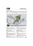
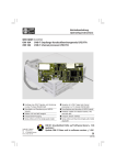
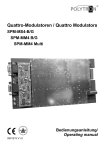
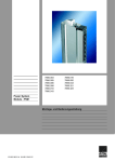
Betriebsanleitung Operating instructions WISI MINI HEADEND OM 17A OM 15A DVB-S - PAL Empfangsmodul (FTA+CI) / DVB-S to PAL channel processor module (FTA+CI) TS - PAL Kanalaufbereitungsmodul (FTA+CI) / TS to PAL channel processor module (FTA+CI) OM 01 Grundeinheit bitte auf Software-Stand > 1.40 updaten! Update OM 01 Base unit to software version > 1.40! OM 17A OM 15A Empfang eines DVB-S-Signales und Umsetzung in einen stereo TV-Kanal (PAL/SECAM) Verarbeitung eines DVB-Transportstromes (TS) und Umsetzung in einen stereo TV-Kanal (PAL/SECAM) Demultiplexing und Decodierung von MPEG-2-Signa- len Demultiplexing und Decodierung von MPEG-2-Signalen Teletext, VPS und WSS tauglich Transportstrom-Ausgang Teletext, VPS und WSS tauglich Transportstrom Ein- Ausgang Stereo, Mono und 2 Ton (single audio mode) Stereo, Mono und 2 Ton (single audio mode) OM 17A OM 15A Reception of a DVB-S signal and channel processing into a stereo TV channel (PAL/SECAM) Processing of a DVB-transport stream signal (TS) and channel processing into a stereo TV channel (PAL/SECAM) Demultiplexing and decoding of MPEG-2 signals Demultiplexing and decoding of MPEG-2 signals Hardware capable for teletext insertion, VPS and WSS data Hardware capable for teletext insertion, VPS and WSS data Transport Stream output Transport Stream input and output Stereo, Mono and Dual tone (single audio mode) Stereo, Mono and Dual tone (single audio mode) 1046 -309 Einbau Module / Installation of moduls Spannungsfrei schalten! Switch off power supply! (A) (A) Die zwei oberen Kreuzschlitzschrauben (A) am Gehäusedeckel lösen und Deckel abnehmen. Modul einsetzen, anschrauben und anschließen. Deckel anschrauben und Einstellungen mit Handset OK 41A vornehmen. Loosen the two upper Philips screws (A) on the cover and remove the cover. Insert the module, screw it down and connect it. Fit and secure the cover and make the necessary settings with the handset OK 41A. Werkseitige Einstellungen/ Factory settings Ausgangsdämpfung / Output attenuator 0 dB Modul in die Führungsschlitze (B) einsetzen und eindrücken. Modul anschrauben (C) und anschliessen. Insert the module into the slots (B) and press down. Tighten (C) and connect it. B C B Legende / Legend TS = Transport Stream FTA = Free To Air CI = Common Interface -2- Folienleiter aufstecken / Attach foil cable OM 17... OM17... OM15... OM 15... Folienleiter in Steckergehäuse eindrücken. Push down foil cable into contact housing. Kontaktfläche oben Upper contact plate Kontaktfläche unten Lower contact plate Anschluss / Connection Vollbestückung / Full assembly Teilbestückung / Partial assembly OUT 470-862MHz OUT 470-862MHz Hinweis: Note: Modul 6 Empfangsmodul Receiver modul 230 VAC Modul 1-2 Kanalaufbereitungsmodule Channel processor modules IN-2 Gain IN-3 Adj. IN-4 IN-5 IN-6 Netzteil Power supply Alimentation IN-1 +5VDC IN-6 Modul 3 IN-5 Modul 2 Modul 5 Modul 4 Modul 3 Modul 2 Modul 1 Modul 1-5 Kanalaufbereitungsmodule Channel processor modules IN-4 Modul 1 IN-3 Adj. Netzteil Power supply Alimentation IN-2 Gain Modul 6 IN-1 +5VDC Modul 3 Empfangsmodul Receiver module 230 VAC Das Empfangsmodul sitzt immer rechts von den Kanalaufbereitungsmodulen. Make sure that the plug in of the receiver module is right hand of the channel processors. Bei Teilbestückung, (z.B. 3 Module), darauf achten, daß der Modulplatz 1+2 bestückt sind, da über diese Modulplätze der Ausgangssammelverstärker mit Betriebsspannung versorgt wird. Please make sure that slot number 1+2 of the basic unit is equipped with a module (OM 15... 17...) in any case (particularly if not all slots are to be used) because this first slot feeds the booster amplifier of the base unit. -3- Anlagenbeispiele mit OM 17A DVB-S und OM 15 / 15A TS Modulen Sample system configurations with OM 17A DVB-S and OM 15 / 15A TS modules OM 14 OM 15 OM 15 / A version Empfang von 4 Programmen aus 1 Transponder / Reception of 4 programs from 1 transponder OM 17A out in out in TS Output TS Durchschleifung TS loop through Module 1................................4 DVB... Eingang / Input Empfang von 6 Programmen aus 2 Transpondern / Reception of 6 programs from 2 transponders OM 14 OM 15 OM 15 OM 17A OM 17A out in TS Durchschleifung TS loop through DVB-T input Module 1.....................3 ..... ....4......................6 DM 12 DVB... Eingang / Input -4- OM 15 / A version out in TS Output Technische Daten / Specifications OM 17A Eingang / Input Frequenzbereich / Frequency range 950-2150 MHz / 75 Ω Abstimmschritte / Tuning steps 1 MHz Eingangspegel / Input level 47 - 70 dBµV AFC + 5 MHz Modulationsart / Modulation type QPSK Symbolrate Filtering Nyquist √cos Roll-Off factor 35% FEC inner code 1/2, 2/3, 3/4, 5/6, 7/8 Spectral inversion C/KU band Interleaving Conv., I=12 FEC outer code RS (204,188,8) Parallel Transport-Strom Interface / Transport Stream Interface OM 17A Ausgang / Output OM 15A Aus- und Eingang / In and output *NTSC auf Anfrage! on request! Gemeinsame Daten / Common specifications OM 15A + OM 17A Videodecoder / Video Decoder ISO 13818-2 / MPEG2 (MP@ML) / 1.5 Mbit/s-15 Mbit/s Format 4:3 / 16:9 Videoformat (einstellbar) / Video format (switchable) PAL / SECAM NTSC* Audiodecoder / Audio decoder ISO 13818-3 / MPEG 2 (L1/2) Audiosprache / Audio language ISO 639 Audioformat / Audio format mono/ stereo / 2 Ton (dual) Ausgang / Output Ausgang / Output impedance 75 Ω Frequenz / Frequency 470 – 862 MHz Abstimmschritte / Tuning steps 250 kHz Modulation / Modulation Zwei-Seitenband / Double sideband Pegel / Level 78 dBµV TV-Standard / TV-standard B/G, D/K, I, L, M Testbild-Generator / Test pattern generator s/w und Farbe black/white and color bar Allgemeines / General data Anschlüsse / Connectors - HF-Ausgang / RF output F LIF flexibles Flachbandkabel / - Transport-Stream LIF connector for flexible foil cable - Betriebsspannung / Power supply PCB-Anschluß / PCB connector - Common Interface PCMCIA Betriebsspannung / 3,6 V DC OM15A/17A 160 mA/360 mA + CI Power supply 5,2 V DC OM15A/17A280 mA/480 mA + CI LNB 14/18 V DC Leistungsaufnahme / Power consumption < 4 W + CI Modul Betriebstemperaturbereich / Operating temperature 0°C ... +55°C Lagertemperatur / Storage temperature -25°C ... +75°C Max. Luftfeuchte nicht kondensierend / 95 % Max. humidity non condensing Abmessungen / Dimensions 90 x 200 x 15 mm -5- Anschluß Handset an Buchse einstecken. Betriebsspannung anschließen. Display zeigt Information: WISI OM Startup. Handset OM... (Zubehör) WISI Mini OM V1.35 Headend Ein zunehmender Balken zeigt den Initialisierungsvorgang an. Beliebige Taste drücken. „Search modules“mit rotierendem„\“ erscheint. Display erscheinen die gefundenen Module: 1 OM 15A Ch 21 2 OM 15A Ch 23 . . 5 OM 15A Ch 29 6 OM 17A Ch 31 Up Erklärung der Tastenfunktion Right Left Down Tasten — Bedienschritt wählen. Taste — Weiter zum Untermenü. Taste — Zurück zum Bedienschritt und mit Tasten nächsten Bedienschritt wählen. Untermenü Legende: L/R-Taste =Left/Right Tasten — Anzeige oder zu ändernden Wert wählen. Cursor steht unter dem Wert 89 Tasten — Wert ändern. Hinweis: Bei Erst-Inbetriebnahme zuerst die System-Parameter einstellen! Modul Parametereinstellung mit Handset (Beispiele) Bedienschritte Display Einstellungen OM 17A Einzustellendes Modul 6 wählen 5 OM 15A Ch 29 6 OM 17A Ch 31 Mit UP/DOWN-Taste Modul wählen und mit R-Taste bestätigen. SAT-ZF-Eingangsfreq. 950-2150 MHz Module6 OM 17A SatFrq: 1234 MHz Cursor_ mit L/R-Taste auf Dezimalstelle schieben und mit UP/DOWN-Tasten einstellen. Symbolrate 1000-45000 KS/s Module6 OM 17A SymRat: 27500 KS/s Cursor_ mit L/R-Taste auf Dezimalstelle schieben und mit UP/DOWN-Tasten einstellen. Eingangs- BER Bit Error Rate Module6 OM 17A InBER: 6.9 e-4 Die BER ist ein Mass für die Übertragungsfehler und damit für die Signalqualität. (nur Anzeige) <1.0 e-4 1.0 e-3 = 1.0 e-2 = Signalstärke Module6 OM 17A InSign: -6- = sehr geringe Fehler geringe Anzahl von Fehler Schaltschwelle für Anzeige: Signal? OM 17A+15A Program-Name Module6 OM 17A PgName Mit UP/DOWN-Tasten wählen. Bsp. Das Erste, ARTE Sprachen Module6 OM 17A Mit UP/DOWN-Tasten wählen. Lang Bsp. deu, fra VPS-Steuerung VPS Teletext Auswahl der Datenquelle für VPS- EIT / PDC Steuerung. EIT= Event Information Table PDC= Program Delivery Control (wenn vom Provider unterstützt) Untertitel 2) (aus Tabelle) SubtTyp DVB Auswahl der Datenquelle. (werden nur angezeigt, wenn Teletxt sie gesendet werden und aus SubT-1 der Tabelle gewählt wurden). SubT-2 2) Tabelle Untertitel / Sprache eng ger/deu fra/fre Untertitel 1 werden angezeigt (bevorzugt). Untertitel 2 werden ersatzweise für Untertitel 1 Untertitel ausgeschaltet. off swe/sve den/dan fin/suo nor ita spa dut/net rus chi/mdr cze/tr2 hun rum/rom pol por jpn/jap gre lit lat est kor ara AudioMode ab OM 01 Software Version 1.40 *empfohlene Einstellung Module6 OM 16A AudMod - Auto* - Stereo - Dual - Mono-R - Mono-L - Reverse autom. Umschalten Stereo - 2 Tonsignal Stereo 2 Tonsignal Auf beiden Stereokanälen wird der Rechtebzw. Linke-Kanal mono übertragen. Wie bei Auto, nur beide Kanäle vertauscht Audiopegel -12 dB...+12 dB Module6 OM 17A AudLev: +00 Cursor_ mit L/R-Taste auf Dezimalstelle schieben und mit UP/DOWN-Tasten einstellen. Testbild Module6 OM 17A TstPic: off Mit UP/DOWN-Tasten wählen. off = kein Testbild CB = Farbbalken BW = Schwarz/weiss-Balken mit 1-kHz-Signalton Screen Module6 OM 17A Screen Mit UP/DOWN-Tasten wählen. 4:3 Format 16:9 Format nicht angepasst auf 4:3 Format 4:3 Zoom: Das 16:9 Format wird auf 4:3 Format angepasst, indem das Bild vertikal abgeschnitten wird. TV-Standard Module6 OM 17A B/G, D/K, I, L, M TV-Std: BG B/G Stereo / D/K Stereo Mit UP/DOWN-Tasten wählen. -7- Diese Anzeige hängt von den System-Einstellungen „Ausgangsfrequenz Channel/Freq.“ ab Ausgangsfrequenz Module6 OM 17A 470-862 MHz OutFrq: 471.25 MHz oder Kanal einstellen OutFrq: Ch 21 Ch 21-69 Software-Version Sw-Ver Module1 (nur Anzeige) Hardware-Version Hw-Ver Module1 Cursor_ mit L/R-Taste auf Dezimalstelle schieben und mit UP/DOWN-Tasten einstellen. Hinweis: Die Einstellungen werden mit 1 Kanal Abstand ausgeführt. z.B.: Ch 21, Ch 23 ansonsten erscheint ein Warnhinweis ??? Mit UP/DOWN-Tasten Modul wählen und mit RTaste bestätigen. Mit UP/DOWN-Tasten Modul wählen und mit R- System-Parameter Einstellungen (Bsp. OM 01 bestückt mit 5 x OM 15A und 1 x OM 17A) System-Einstellungen 6 OM 17A Ch 31 wählen System settings Mit UP/DOWN-Tasten die Zeile „System settings wählen. Mit Taste RIGHT „LNB- Einstellungen“ wählen. 1 OM 15A Ch 21 2 OM 15A Ch 23 3 OM 15A Ch 25 4 OM 15A Ch 27 5 OM 15A Ch 29 6 OM 17A Ch 31 System settings mit den UP/DOWN-Tasten. LNB-Einstellung wählen LNBSet System Ch/Frq settings Mit UP/DOWN-Tasten auswählen. LNB-Spannung 14V 0kHz, 14V -22 kHz 18V 0kHz, 18V -22 kHz System Settings LNBSet: 14V 0kHz Mit UP/DOWN-Tasten auswählen. Ausgangsfrequenz System Settings Mit UP/DOWN-Tasten Kanal- oder Frequenzan zeige auswählen. Channel / Freq. Ausgangsdämpfung 0...10 dB Cursor_ mit L/R-Taste auf Dezimalstelle schieben und mit UP/DOWN-Tasten einstellen. Ch/Frq: Channel System Settings OutAtt: 3 Software-Version Sw-Ver Module1 (Anzeige) Mit UP/DOWN-Tasten auswählen und mit R-Taste bestätigen. Hardware-Version Hw-Ver Module1 (Anzeige) Mit UP/DOWN-Tasten auswählen und mit R-Taste bestätigen. -8- Handset OM... (accessory) WISI Mini OM V1.35 Headend Plug the handset into socket . Connect the supply voltage. Display shows information WISI OM Startup. A continuously bar shows the initialisation. Press any button. „Search modules“with rotating „\“ is displayed. Display shows the modules: 1 OM 15A CH 21 2 OM 15A CH 23 . . 5 OM 15A CH 29 6 OM 17A CH 31 Up Operation of the buttons Right Left Down Legend: L/R keys =Left/Right keys — Select Operation. key — Open sub-menu. key — Back to operation. Select with buttons next operation. Parameter sub-menu keys keys — Select display or value to be changed. Cursor stands under the value, e.g. 89 — Change the value. Note: 1st Start Up: Set System parameters first Modul parameter settings with handset Operation Display Settings OM 17A Select modul 6 5 OM 15A Ch 29 6 OM 17A Ch 31 Select with UP/DOWN buttons and confirm with R button. SAT frequency 950-2150 MHz Module 6 OM 17A SatFrq: 1234 MHz Move cursor with L/R keys to digit to be changed and adjusted with UP/DOWN keys. Symbol rate 1000-45000 KS/s Module 6 OM 17A SymRat: 27500 KS/s Move cursor with L/R keys to digit to be changed and adjusted with UP/DOWN keys. Input BER Module 6 OM 17A Bit Error Rate InBER: 6.9 e-4 (only displayed) Signal strength Module 6 OM 17A InSign: The BER is an indication of the number of transmission errors and thus of the signal quality. <1.0 e-4 = very low numbers of errors 1.0 e-3 = low number of errors 1.0 e-2 = threshold for display: Signal? -9- OM 17A+15A Program name Module 6 OM 17A Select with UP/DOWN buttons. PgName Ex. Das Erste ARTE Language Module 6 OM 17A Select with UP/DOWN buttons. (if provider supports) Lang Ex. deu fra VPS control VPS Teletext EIT / PDC Data base selection for VPS- control. EIT= Event Information Table PDC= Program Delivery Control Subtitle2) (refer to table) SubtTyp DVB Data base selection (are displayed when trans- Teletxt Subtitle 2 is displayed instead of subtitle 1. mitted and selected out of table). SubT-1 Subtitle 1 is displayed (preferred). SubT-2 Subtitle 2 is displayed instead of subtitle 1. eng 2) Table Subtitel / language ger/deu fra/fre off swe/sve den/dan fin/suo nor ita spa Subtitle disabled dut/net rus chi/mdr cze/tr2 hun rum/rom pol por jpn/jap gre lit lat est kor ara AudioMode Module6 OM 16A starting from OM 01 AudMod software version 1.40 - Auto* *recommended setting - Stereo - Dual - Mono-R - Mono-L - Reverse autom. switching stereo - dual signal Stereosignal Dual signal R or L channel is transmitted on both stereo channels as mono signal Identical with Auto mode, stereo - dual channel inverse Audio level -12 dB...+12 dB Move cursor with L/R keys to digit to be changed and adjusted with UP/DOWN keys. Module 6 OM 17A AudLev: +00 Test picture Module 6 OM 17A TstPic: off Select with UP/DOWN buttons. off = no test picture CB = Color bars BW = black/white bars with 1-kHz- signal Screen Module 6 OM 17A Screen Select with UP/DOWN buttons. 4:3 format 16:9 format not adapted to 4:3 format 4:3 Zoom to match the 16:9 to 4:3 format, the vertical screen format is cut. TV standard B/G, D/K, I, L, M B/G stereo/D/K stereo Select with UP/DOWN buttons. - 10 - Module 6 OM 17A TV-Std: G - 11 - ... a link to the future - 12 - Technische Änderungen und Druckfehler vorbehalten! Technical Modifications reserved. WISI cannot be held liable for any printing error. 09/07 WISI Communications GmbH & Co. KG Empfangs- und Verteiltechnik Wilhelm-Sihn-Straße 5-7, 75223 Niefern-Öschelbronn Tel . 07233 / 66-292, Fax. 66-320, http://www.wisi.de