1
JNCIP
Juniper® Networks
Certified Internet Professional
Study Guide - Chapter 1
by Harry Reynolds
This book was originally developed by Juniper Networks Inc. in conjunction with
Sybex Inc. It is being offered in electronic format because the original book
(ISBN: 0-7821-4073-4) is now out of print. Every effort has been made to remove
the original publisher's name and references to the original bound book and its
accompanying CD. The original paper book may still be available in used book
stores or by contacting, John Wiley & Sons, Publishers. www.wiley.com.
Copyright © 2003-6 by Juniper Networks Inc. All rights reserved.
This publication may be used in assisting students to prepare for a Juniper
JNCIP exam but Juniper Networks Inc. cannot warrant that use of this
publication will ensure passing the relevant exam.
Chapter
1
Initial Configuration
and Platform
Troubleshooting
JNCIP LAB SKILLS COVERED IN THIS
CHAPTER:
Use terminal server to access router console ports
Configure OoB management network and host name
Create user accounts and system authentication options
Configure syslog parameters
Configure network management and NTP
Determine JUNOS software version and perform upgrades
Configure chassis alarms and redundancy
In this chapter, you will be exposed to configuration tasks that are
characteristic of those encountered when installing a brand-new
M-series or T-series router. These initial configuration and maintenance tasks include setting up the Out of Band (OoB) management network, user accounts
and permissions, the Network Time Protocol (NTP), syslog parameters, chassis alarms, redundancy, and maintaining JUNOS software.
You will learn numerous JNCIP-level configuration requirements along with the commands
needed to correctly configure a Juniper Networks router for that task. Wherever possible, you
will also be provided with techniques that can be used to verify the operation and functionality
of the various elements that make up your system’s configuration. The chapter concludes with
a case study that is designed to closely approximate a typical JNCIP initial system configuration
scenario. A router configuration that meets all case study requirements is provided at the end
of the case study for comparison with your own configuration.
To kick things off, you will need to access the console ports of your assigned routers using
reverse telnet connections though a terminal server. As you establish initial contact with each
of your routers, you should make note of the types of routers provided in your test bed and be
on guard for any symptoms of hardware malfunction or aberrant operation.
Faulty hardware is never intentionally given to a JNCIP candidate, but hardware
failures do occur. In view of the time pressures associated with the JNCIP practical examination, you would be wise to bring suspicions of faulty hardware to
the proctor’s attention as soon as possible. The proctor will confirm whether
there is actually a problem and may provide workaround instructions as needed.
Before calling in the proctor, it is generally a good idea to try rebooting the
router, because symptoms of bad hardware may be caused by software malfunctions that are sometimes cleared by a reboot.
Task 1: Access Routers Using a Terminal
Server
As described in the introduction, your JNCIP test bed consists of seven freshly flashed M-series
routers, a terminal server, and a 100Mbps Fast Ethernet LAN segment that will serve as your
network’s Out of Band (OoB) management network. Because your routers have a factory-fresh
Task 1: Access Routers Using a Terminal Server
3
default configuration, you will not be able to telnet to the routers until you have correctly configured the OoB management network. Therefore, you should plan on accessing the console ports
of the routers assigned to your station using an IOS-based (2517 or similar) terminal server to perform your initial configuration task. Since the actual examination does not involve non–Juniper
Networks products, you will be instructed on how to use the particular terminal server used at
your testing center.
Although you can use the router console ports for the duration of the examination, most candidates find that it saves time to open multiple telnet sessions (one
per router) using the Out Of Band (OoB) management network that is configured
during the examination. You should use the terminal server whenever you are
performing router maintenance (such as upgrading JUNOS software), or when
routing problems cause telnet access problems.
Console Connections
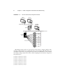
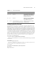
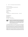
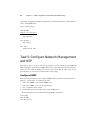
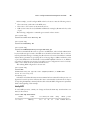
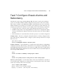
The OoB (Out of Band) management topology is illustrated in Figure 1.1. Based on this figure,
you can see that the IP address of the terminal server is 10.0.1.101, and that its asynchronous
interfaces are connected in ascending order to the console ports of each router that is associated
with your test pod.
The testing center will provide you with both user EXEC and privileged EXEC mode passwords for the terminal server (or their equivalents should a non–IOS-based terminal server be
in use). You’ll sometimes need the privileged EXEC mode login to reset connections when you
receive error messages about ports being busy or when you see messages about connections
being refused. The following is an example of a typical login session to the terminal server:
telnet 10.0.1.101
Trying 10.0.1.101...
Connected to 10.0.1.101.
Escape character is ‘^]’.
User Access Verification
Password:
cert-ts>enable
Password:
cert-ts#
Chapter 1
4
FIGURE 1.1
Initial Configuration and Platform Troubleshooting
The Out of Band (OoB) management network
RADIUS,
SNMP, FTP, etc.
10.0.200.0/24
Proctor
Workstation
.2
.1
Candidate
Workstation
Firewall
.102
.101
.100
10.0.1.0/24
r1
fxp0
Terminal
Server
fxp0
fxp0
fxp0
Console Ports
fxp0
fxp0
r7
fxp0
Depending upon the specifics of your test bed, you may want to configure symbolic name
mappings on the terminal server to simplify the task of reverse telnetting. This will enable you to
use symbolic names in lieu of specifying the reverse telnet port and IP address on the command
line. In the preceding example, these name-to-address mappings have already been configured on
the terminal server:
ip
ip
ip
ip
ip
ip
ip
host
host
host
host
host
host
host
r1
r2
r3
r4
r5
r6
r7
2001
2002
2003
2004
2005
2006
2007
10.0.1.101
10.0.1.101
10.0.1.101
10.0.1.101
10.0.1.101
10.0.1.101
10.0.1.101
Task 1: Access Routers Using a Terminal Server
5
In this configuration, you can see that port 2001 on the terminal server, which maps to its
first asynchronous port, is associated with the symbolic name of r1. Now, to establish a reverse
telnet connection to the console port of router 1, the user need only enter r1 on the terminal
server’s command line. If host mappings have not been configured on your terminal server, you
will need to specify the correct port identifier and IP address on the command line, as shown here:
cert-ts#telnet 10.0.1.101 2001
Trying 10.201.1.253, 2001 ... Open
<operator hits “enter”>
Amnesiac (ttyd0)
login:
In the foregoing example, you can see that the reverse telnet session to r1 has succeeded, in
that the router is now presenting its login prompt.
The Amnesiac prompt shown in the previous example is indicative of a router
that is booting from a factory-fresh JUNOS software load, which, by definition,
will not have a hostname configured. When preparing the lab for JNCIP testing,
it is standard practice for the proctor to flash every router using removable media
(PCMCIA) cards at the end of each certification attempt. This ensures that each
new candidate will begin his or her test from a known starting point and will
prevent possible difficulties caused by a previous candidate’s tampering with
the system’s binaries or file structure.
Initial Console Login
Because the router is booting from a factory-fresh load, the only existing login account will be
the user root. Initially, this account has no associated password. When logging in as root, the
user is presented with the shell prompt, so the JUNOS software command-line interface (CLI)
must be started manually as shown here:
login: root
--- JUNOS 5.2R1.4 built 2002-03-10 01:12:05 UTC
Terminal type? [vt100]
root@% cli
root>
6
Chapter 1
Initial Configuration and Platform Troubleshooting
Switching Among Reverse Telnet Sessions
Although the reverse telnet sessions can be opened in any order, it is highly recommended that
you open the sessions to your routers in a sequential fashion. This will make it easy to switch
among sessions using session numbers that map directly to corresponding router numbers. To
regain the IOS command prompt, the user must enter an escape sequence consisting of a simultaneous Ctrl+Shift+6 followed by pressing the x key (the escape sequence is not echoed back to
the user but is shown in angle brackets in the following to illustrate use of the escape sequence):
root> <control-shift-6 x>
pod2-ts#r2
Trying r2 (10.0.1.101, 2002)... Open
Amnesiac (ttyd0)
login:
After entering the escape sequence, the user is presented with an IOS prompt. If the user simply presses Enter at this point, the connection to r1 will be resumed. In this example, the user
establishes a reverse telnet session to the next router (router 2) using the symbolic name r2. To
switch between these two sessions, the user can now enter the escape sequence followed by the
connection number, which will be either a 1 or a 2 at this stage:
login: <control-shift-6 x>
pod2-ts#1
[Resuming connection 1 to 10.0.1.101 ... ]
root>
Clearing Terminal Server Sessions
Although it’s rarely necessary, sometimes you have to manually clear one or more reverse telnet
sessions on the terminal server when connections cannot be correctly established to a given
router’s console port. This will require that you regain a privileged EXEC mode IOS command
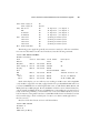
prompt to display and clear the problem line. Listing 1.1 is an example of this process. It demonstrates the clearing of Line 2 after a problem with access to r2 has been encountered:
Listing 1.1: Clearing Terminal Server Lines (IOS-Based Terminal Server)
pod2-ts#r2
Trying r2 (10.0.1.101, 2002)...
% Connection refused by remote host
Task 1: Access Routers Using a Terminal Server
pod2-ts#show line
Tty Typ
Tx/Rx
0 CTY
* 1 TTY
9600/9600
* 2 TTY
9600/9600
3 TTY
9600/9600
4 TTY
9600/9600
5 TTY
9600/9600
6 TTY
9600/9600
7 TTY
9600/9600
8 TTY
9600/9600
9 TTY
9600/9600
10 TTY
9600/9600
11 TTY
9600/9600
12 TTY
9600/9600
13 TTY
9600/9600
14 TTY
9600/9600
15 TTY
9600/9600
16 TTY
9600/9600
17 AUX
9600/9600
* 18 VTY
19 VTY
20 VTY
21 VTY
22 VTY
A Modem
-
Roty AccO AccI
-
Uses
0
3
4
3
3
1
1
1
1
1
2
0
0
0
0
0
0
0
26
0
0
0
0
Noise
0
0
2031
1546
0
0
72050
19691
0
0
0
0
0
0
0
0
0
0
0
0
0
0
0
7
Overruns
0/0
0/0
0/0
0/0
0/0
0/0
3/0
1/0
0/0
0/0
0/0
0/0
0/0
0/0
0/0
0/0
0/0
0/0
0/0
0/0
0/0
0/0
0/0
pod2-ts#clear line 2
[confirm]y [OK]
pod2-ts#r2
Trying r2 (10.0.1.101, 2002)... Open
<user hits enter>
Amnesiac (ttyd0)
login:
Reverse telnet sessions connect the user to a tty (asynchronous terminal line) on the terminal
server. You will want to focus on tty sessions that have an asterisk (*) next to them, because this
character indicates the line is in use. To clear a line, enter the clear line n command at the
privileged EXEC mode prompt, and confirm the clear by entering y when prompted.
8
Chapter 1
Initial Configuration and Platform Troubleshooting
A Caution About Clearing Sessions
The “failure” described in Listing 1.1 was simulated by trying to open a second telnet session
to port 2002 on the terminal server without first clearing the existing session. The operator
should have simply entered the session number (2 in this case) to switch back to the previously
established connection to resume the connection to router r2. Clearing sessions in the manner
described can result in session numbers that are no longer directly related to router numbers,
which can be very confusing—for example, the session associated with r2 might end up being
number 8. When reverse telnet problems are detected, many candidates find it simpler to simply
log out of an IOS-based terminal server, which causes the terminal server to clear all existing
connections (after the user confirms). After reconnecting to the terminal server, the telnet sessions to all routers can be reestablished in the correct numeric sequence.
Task 2: Configure the OoB Management
Network
Once you have opened reverse telnet sessions to each of the routers assigned to your test bed, you
will want to configure and test the fxp0-based OoB management network and assign the correct
hostname to each router. Once again referring to Figure 1.1, you can see that each router’s fxp0
interface connects to a shared Ethernet segment with a logical IP subnet of 10.0.1.0/24. Also, the
host value of each fxp0 address must match the router number, so router 1 will have the address
10.0.1.1 assigned to its fxp0 interface. The OoB management network must be reachable from the
proctor’s workstation, which is attached to subnet 10.0.200/24 behind a firewall router.
Because each router also requires a unique name, it makes sense to configure the router’s
hostname along with the OoB addressing and telnet service at this point. The following commands, entered on r1, will set the correct IP address and hostname for this exercise, and will
enable the telnet service:
root> configure
Entering configuration mode
[edit]
root# set system host-name r1
[edit]
root# set interfaces fxp0 unit 0 family inet address 10.0.1.1/24
[edit]
root# set system services telnet
Task 2: Configure the OoB Management Network
9
The resulting configuration is now as follows:
[edit]
root# show interfaces
fxp0 {
unit 0 {
family inet {
address 10.0.1.1/24;
}
}
}
[edit]
root# show system
host-name r1;
services {
telnet;
}
syslog {
user * {
any emergency;
}
file messages {
any notice;
authorization info;
}
}
With the correct configuration now in r1, you decide to commit the changes to place them
into effect:
[edit]
root# commit and-quit
commit complete
Exiting configuration mode
root@r1>
After the candidate configuration has been successfully committed, the router’s command
prompt takes on the newly assigned hostname. Although the configuration steps performed thus
far will make telnet access available to the candidate, the router currently does not have a route
back to the proctor’s subnet, which will prevent proctor-initiated telnet connection to your
10
Chapter 1
Initial Configuration and Platform Troubleshooting
routers. To rectify this situation, you must add a static route on each router for the 10.0.200/24
proctor subnet, using the firewall router (10.0.1.102) as the next hop. This route should have
the no-readvertise tag to ensure the router does not inadvertently redistribute the static route
in a later lab scenario. The following commands create the necessary static route and show the
resulting configuration change:
[edit routing-options static route]
root@r1# set 10.0.200/24 next-hop 10.0.1.102 no-readvertise
[edit routing-options]
root@r1# show
static {
route 10.0.200.0/24 {
next-hop 10.0.1.102;
no-readvertise;
}
}
To confirm that the OoB management network and static routing are operational, try to ping
the RADIUS/FTP server on the proctor subnet, like this:
root@r1> ping 10.0.200.2
PING 10.0.200.2 (10.0.200.2): 56 data bytes
64 bytes from 10.0.200.2: icmp_seq=0 ttl=255 time=1.228 ms
64 bytes from 10.0.200.2: icmp_seq=1 ttl=255 time=0.701 ms
^C
--- 10.0.200.2 ping statistics --2 packets transmitted, 2 packets received, 0% packet loss
round-trip min/avg/max/stddev = 0.701/0.964/1.228/0.264 ms
Based on the successful results shown in this output, things are now looking good for your
OoB management network.
Task 3: Create User Accounts
When the OoB management network and its associated routing are confirmed to be operational,
you will likely want to configure various user accounts. These accounts should make use of both
local and remote authentication, and should also verify your ability to use allow and deny commands to provide local control of user authorization levels.
In the example shown in Table 1.1, the following accounts (and permissions) will be configured to demonstrate typical user account configuration and validation techniques.
Task 3: Create User Accounts
TABLE 1.1
11
User Account Parameters
User
Password Class/Permission
Notes
root
root
superuser
SSH with 1024-bit RSA public key
authentication. Local password and
RADIUS authentication criteria are
the same as for user lab.
lab
lab
superuser
RADIUS/local password with automatic login in the event of RADIUS
failure. RADIUS secret is jni.
ops
operator
Can view standard show interfaces RADIUS/local password, 5-minute
output and conduct ping testing only. inactivity time-out.
Configuring the Root Account
As noted in Table 1.1, the root user’s account must be configured for SSH public key and
RADIUS/local password authentication. The following commands configure the root account
with the required SSH version 1 RSA public key (version 2 RSA keys are not supported at the time
of this writing so a version 1 key must be loaded). It is important to note that the operator must
manually add the opening and closing quotes ("") so that white spaces in the key string do not
cause syntax errors if the key is pasted from a terminal buffer. You could also choose to edit the
~/.ssh/authorized_keys file manually to add the public RSA key (by escaping to a shell and
using vi), or you could transfer the key file to the router using the load-key-file option with an
appropriate URL, such as ftp://user:password@hostname/file-name. However, the CLI
paste approach demonstrated here is generally considered to be the most straightforward:
[edit system root-authentication]
root@r1# set ssh-rsa “key-data-pasted-from-terminal”
And now, to enable the SSH service on the router, which by default will support both SSH
version 1 and 2:
[edit system]
root@r1# set system services ssh
Since the use of SSH public key authentication for the root account has no effect on local
console-based logins, we also set the required root password:
[edit system]
root@r1# set root-authentication plain-text-password
New password:
Retype new password:
12
Chapter 1
Initial Configuration and Platform Troubleshooting
The following is the resulting configuration for the root account and the SSH service:
[edit system]
root@r1# show root-authentication
encrypted-password “$1$n/lx3$RNtF9uDlCsMsAL8gi/qA31”; # SECRET-DATA
ssh-rsa “1024 65537
14507521839282798432482521835023055326381401663452058669080886491465544700784392
81114055822376198290722320666268020211763429857348456378696103199986915461962494
35479692894437417780898017483440313841107367122670080439972894195679320796753410
731222833899141869327583231170906047985814682544941905107416839803283 root”; #
SECRET-DATA
lab@r2# show system services
ssh;
telnet;
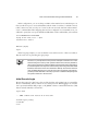
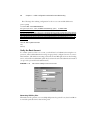
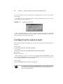
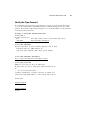
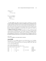
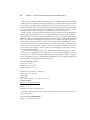
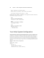
Verify the Root Account
To confirm operation of the root account, you should test local authentication using the root
password, and test SSH authentication using an appropriately configured session on your terminal emulator. The SSH session settings used in the SecureCRT application are shown in Figure 1.2; it should be noted that RSA (public key) has been selected as the authentication method
(as opposed to password-based authentication).
FIGURE 1.2
SSH session settings for the root account
Generating SSH Key Pairs
The method used to generate your own SSH public/private key pair will vary based on SSH version and the particular client software being used.
Task 3: Create User Accounts
13
For a Unix-like operating system Generate a 1024-bit SSH version 1 RSA key pair using the
ssh-keygen program with the –b flag set to 1024 and the -t flag set to rsa1. By default, the
resulting public key will be written to $HOME/.ssh/identity.pub. The contents of this file
would then be loaded into the router using the techniques described in the section “Configuring
the Root Account” earlier in this chapter. Typical ssh-keygen output is shown here:
[harry@dr-data harry]$ ssh-keygen -b 1024 -t rsa1
Generating public/private rsa1 key pair.
Enter file in which to save the key (/home/harry/.ssh/identity):
Enter passphrase (empty for no passphrase):
Enter same passphrase again:
Your identification has been saved in /home/harry/.ssh/identity.
Your public key has been saved in /home/harry/.ssh/identity.pub.
The key fingerprint is:
d1:ac:20:9b:f6:82:04:06:09:69:11:57:66:8d:17:be [email protected]
After loading the resulting public key into the router, SSH connectivity can be tested:
[harry@dr-data harry]$ ssh -l root -1 10.0.1.1
The authenticity of host '10.0.1.1 (10.0.1.1)' can't be established.
RSA1 key fingerprint is 10:e1:82:2f:6b:c3:9c:5e:84:d5:6c:0b:df:1c:3d:ea.
Are you sure you want to continue connecting (yes/no)? yes
Warning: Permanently added '10.0.1.1' (RSA1) to the list of known hosts.
Enter passphrase for RSA key '/home/harry/.ssh/identity':
Last login: Wed May 15 17:38:58 2002 from 10.0.1.201
--- JUNOS 5.2R2.3 built 2002-03-23 02:44:36 UTC
root@r1%
In this example, the -l switch was needed to indicate that the remote login name should be
root instead of the user’s local Unix login name, which would be harry in this case. The -1 was
also needed to indicate that SSH version 1 should be used, because the SSH configuration on this
author’s Linux machine causes it to first try SSH version 2.
For the SecureCRT application Generate a key pair by clicking the Advanced button in the
SSH Quick Connect dialog box, followed by selecting the Create Identity File option in the
resulting Advanced SSH Options dialog box, which will open the SecureCRT Key Generation
Wizard. The wizard will guide you through the remaining key generation steps. When the Wizard completes, you will be prompted to enter the directory and key filenames for your newly
generated secret and public keys. When using SecureCRT version 3.1.2, the default location and
filename for the secret key is C:\Program Files\SecureCRT 3.0\identity. The public key
will be stored in the same directory with a .pub file extension. As described in the previous “For
a Unix-like Operating System” section, the contents of this public key file should be loaded into
14
Chapter 1
Initial Configuration and Platform Troubleshooting
the router using the procedures outlined in the “Configuring the Root Account” section earlier
in this chapter.
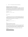
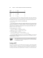
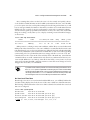
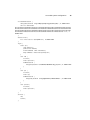
You will be asked to accept a “new host key” when testing SSH connectivity to the router
for the first time, as shown in Figure 1.3.
FIGURE 1.3
Accepting a new host key
After accepting the host key, you will be prompted to enter the pass phrase associated with
the session’s private key. When the correct pass phrase is entered, you should be logged in as the
root user and presented with a shell prompt.
Configuring the Lab Account
The following commands establish the lab account and associate the user with the superuser
login class:
[edit system]
root@r1# set login user lab class superuser
[edit system]
root@r1# set login user lab authentication plain-text-password
New password:
Retype new password:
Because the lab, root, and ops accounts are to be authenticated through RADIUS, you must
now configure the RADIUS server’s properties. The RADIUS-related parameters needed for this
task are configured with the following commands:
[edit system]
lab@r1# set radius-server 10.0.200.2 secret jni
If your test bench does not offer RADIUS support, you can reduce the delay
associated with the failed RADIUS authentication requests by setting the retry
and timeout parameters to 1.
Configuring the Lab Account
15
To tell the system that RADIUS authentication is to be used first, you must specify radius
as the first entry in the system’s authentication-order list with the following command:
[edit system]
root@r1# set authentication-order radius
The resulting lab account and RADIUS configuration are shown next:
root@r1# show login user lab
class superuser;
authentication {
encrypted-password “$1$nNISN$o7OGTEhEF5sOcgjS9p0Lf0”; # SECRET-DATA
}
root@r1# show radius-server
10.0.200.2 secret “$9$NQVs4Pfz36A”; # SECRET-DATA
[edit system]
root@r1# show authentication-order
authentication-order radius;
Verify the Lab Account
To verify the lab account, we log out as root and reconnect as the lab user:
root@r1% exit
logout
r1 (ttyd0)
login: lab
Password:
Last login: Fri Mar
8 16:20:47 on ttyd0
--- JUNOS 5.2B3.1 built 2001-12-28 18:50:44 UTC
lab@r1>
Though the previous capture indicates that your user account is functional, notice the terminology “automatic login in the event of RADIUS failure” in Table 1.1, shown earlier. This should
cause you to wonder what would happen if the RADIUS server should become unreachable. To
simulate a RADIUS failure, the shared secret is changed to foo and the lab account is retested:
[edit system radius-server]
lab@r1# set 10.0.1.102 secret foo
Chapter 1
16
Initial Configuration and Platform Troubleshooting
[edit system radius-server]
lab@r1# commit and-quit
commit complete
Exiting configuration mode
lab@r1> quit
r1 (ttyd0)
login: lab
Password:
Local password:
Last login: Mon Apr
1 12:36:17 on ttyd0
--- JUNOS 5.2B3.1 built 2001-12-28 18:50:44 UTC
lab@r1>
Note the second prompt that asks for a local password. This indicates that automatic login
is not functional. The problem lies in the omission of the password keyword in the system’s
authentication-order statement. Adding password after radius will cause the router to
automatically verify the user’s password against the local password database when access to the
RADIUS server fails. To meet the configuration criteria, you must enter the following command
to add password to the router’s authentication order list:
[edit]
lab@r1# set system authentication-order password
[edit]
lab@r1# show system authentication-order
authentication-order [ radius password ];
[edit]
lab@r1# commit and-quit
commit complete
Exiting configuration mode
With the changes committed, we now retest the lab login:
lab@r1> quit
r1 (ttyd0)
Configure the Ops Account
login: lab
Password:
Last login: Mon Apr
17
1 12:41:09 on ttyd0
--- JUNOS 5.2B3.1 built 2001-12-28 18:50:44 UTC
lab@r1>
The user is now automatically logged in using the local password database when access to
the RADIUS server is broken. After testing, you should reset the shared RADIUS secret to the
correct value as specified in Table 1.1, shown earlier.
The local password database is not consulted when the RADIUS server returns
an access reject message because of an unknown username or incorrect
password being used. You will need to remove (or deactivate) the system’s
RADIUS configuration or change the authentication order to allow local logins
if you feel that the RADIUS server has been misconfigured with regard to a
given account’s username or password.
Configure the Ops Account
You will now configure a user called ops that is only authorized to view the output of show
interfaces and conduct ping testing.
The commands in Listing 1.2 configure the ops account and display the resulting configuration:
Listing 1.2: Commands for Configuring the Ops Account
[edit system login]
root@r1# set user ops class ops authentication plain-text-password
New password:
Retype new password:
[edit system login]
root@r1# set class ops permissions network
[edit system login class]
root@r1# set ops idle-timeout 5
[edit system login class]
root@r1# set ops allow-commands “show interfaces $”
18
Chapter 1
Initial Configuration and Platform Troubleshooting
[edit system login class]
root@r1# set ops deny-commands “traceroute|telnet|ssh”
[edit system login class]
root@r1# up
[edit system login]
root@r1# show user ops
uid 2002;
class ops;
authentication {
encrypted-password “$1$SgJQQ$VYXXLPf9/TMOnb2ohWxOJ.”; # SECRET-DATA
}
[edit system login]
root@r1# show class ops
idle-timeout 5;
permissions network;
allow-commands “show interfaces”;
deny-commands “traceroute|telnet|ssh”;
Because these user account requirements involve custom settings of login class
permissions, care should be taken to avoid the use of the predefined login
classes (operator, read-only, superuser, and unauthorized). The parameters
associated with these accounts cannot be modified. Depending on the JUNOS
software version being used, you may be allowed to configure customized
settings for the predefined login classes, but these changes will not actually
have any effect on their default permissions.
This configuration example illustrates one possible solution to the ops account restrictions as
specified in this example. In this case, we begin with a login class that contains only the network
permission, which, by default, allows only access to the ping, telnet, traceroute, and SSH commands. Because the ops user should have access only to the ping utility, the deny-commands
option was used with a regular expression to explicitly deny access to the telnet, traceroute, and
SSH commands. In a similar fashion, the allow-commands option was included in the ops class
to explicitly permit the use of the show interfaces command. Further, the nature of this allowcommands regular expression will not allow arguments such as detail or terse with the show
interfaces command, so the ops user will be able to issue only the standard show interfaces
command. In contrast, specifying show interfaces$ as the regular expression for allowed commands will provide access to the full range of options supported by the show interfaces command.
Configure the Ops Account
19
Verify the Ops Account
To confirm the ops login and account permissions, we log in as ops and verify that we have
access to the standard show interfaces and ping commands. Listing 1.3 shows you this
sequence. Based on the results shown in Listing 1.3, you can see that all the account restrictions
for the ops user have been met.
Listing 1.3: Verify Ops Account Permissions
ops@r1> show ?
Possible completions:
host
Host name lookup service using domain name server
interfaces
Show interface information
ops@r1> show interfaces
Physical interface: fe-0/0/0, Enabled, Physical link is Down
Interface index: 10, SNMP ifIndex: 13
Link-level type: Ethernet, MTU: 1514, Speed: 100mbps,
. . .
ops@r1> show interfaces fxp0 detail
error: permission denied for interfaces: detail
ops@r1> ping 10.0.1.102
PING 10.0.1.102 (10.0.1.102): 56 data bytes
64 bytes from 10.0.1.102: icmp_seq=0 ttl=255 time=0.560 ms
^C
--- 10.0.1.102 ping statistics --1 packets transmitted, 1 packets received, 0% packet loss
round-trip min/avg/max/stddev = 0.560/0.560/0.560/0.000 ms
ops@r1> tra
^
unknown command.
ops@r1> tel
^
unknown command.
ops@r1>
20
Chapter 1
Initial Configuration and Platform Troubleshooting
Task 4: Configure Syslog Parameters
Now that your user accounts are configured and you have confirmed that they work, you can
move on to adjusting the default syslog parameters. The default syslog configuration on an
M-series router will be similar to this example:
[edit]
lab@r1# show system syslog
user * {
any emergency;
}
file messages {
any notice;
authorization info;
The default syslog settings will display emergency-level messages for all facility classes to any
user that is logged in, and will log at the notice and info levels to the file messages for all facility
classes and for the authorization class, respectively. The default archive settings will allow up
to ten 128KB files that are not world-readable.
In this example, your goal is to modify the default syslog parameters to achieve the following
criteria:
Place authorization messages into a log file named auth
Permit five copies of the auth file, each no larger than 5MB
The commands used to meet these requirements are as follows:
[edit system syslog]
lab@r1# delete file messages authorization
[edit system syslog]
lab@r1# set file auth authorization info
[edit system syslog]
lab@r1# set file auth archive files 5 size 5m
And here is the modified syslog stanza:
[edit system syslog]
lab@r1# show
user * {
any emergency;
}
Task 4: Configure Syslog Parameters
21
file messages {
any notice;
}
file auth {
authorization info;
archive size 5m files 5;
}
Verify Syslog Operation
Verifying the modified syslog parameters is relatively simple. You can open a second telnet connection to the router and monitor the log files while you log in and out, or you can view the log
files offline to confirm that authorization-related information is now being written to both the
auth and messages log files. The second approach is illustrated next:
lab@r1> quit
r1 (ttyd0)
login: anything
Password:
Login incorrect
login: ^CClient aborted login
r1 (ttyd0)
login: lab
Password:
Last login: Mon Apr
1 14:33:26 on ttyd0
--- JUNOS 5.2B3.1 built 2001-12-28 18:50:44 UTC
lab@r1> show log auth
Apr 1 14:36:25 r1 login: 1 LOGIN FAILURE ON ttyd0
Apr 1 14:36:30 r1 login: login on ttyd0 as lab
When modifying the syslog configuration, care should be taken to ensure that the remaining
default settings are left according to the lab scenario’s instructions. For example, the following
syslog configuration sets the default archive parameters of all files at the [edit system syslog]
level and below to five files of 5MB each. Such a setting will also affect the size and number of the
archived messages files stored on your router. Depending on the specifics of your configuration
22
Chapter 1
Initial Configuration and Platform Troubleshooting
requirement, changing the default size and number of archived messages files could result in lost
points on the JNCIP exam:
[edit system syslog]
lab@r1# show
archive size 5m files 5;
user * {
any emergency;
}
file messages {
any notice;
}
file auth {
authorization info;
}
Task 5: Configure Network Management
and NTP
Now that you have correctly set your syslog parameters, we next examine typical SNMP and
NTP configuration requirements. SNMP can be used to pull statistics and operational status
from your router, while the NTP protocol can be used to ensure that all of the routers in your
test bench have an accurate and consistent time-of-day setting.
Configure SNMP
In the following example, we will configure SNMP with the parameters listed next. Refer to
Figure 1.1, shown earlier, for addressing specifics:
Only allow SNMP access from the SNMP server
Only allow SNMP access over the fxp0 interface
Use a community string of test
Send all link up and down related traps to the SNMP server
These requirements are met with the following SNMP configuration:
[edit snmp]
lab@r1# show
interface fxp0.0;
Task 5: Configure Network Management and NTP
23
community test {
clients {
10.0.200.2/32;
}
}
trap-group interface {
categories link;
targets {
10.0.200.2;
}
}
By default, SNMP requests will be accepted over any interface. Specifying one or more interface names under the interface keyword will cause SNMP requests on nonmatching interfaces
to be ignored. Similarly, all clients are allowed to make requests by default; specifying one or more
client IP addresses after the clients keyword causes requests from nonmatching clients to be
ignored. This example includes a trap group named interface that has been configured to send
link up and down traps to the SNMP server by including the link keyword under the categories
hierarchy. By default, both SNMP versions 1 and 2 traps will be sent, but either version can be forced
through appropriate trap group configuration.
SNMP uses community strings for authentication. Failure to include a community string will
result in the denial of all SNMP requests, while specifying the wrong community string will result in
otherwise legitimate requests being denied, so take care when configuring your SNMP community
values, and pay special attention to the community string case as the strings are case sensitive. By
default, SNMP clients are authorized to view only. Read and write access (SNMP get and put) can
be granted by including the read-write keyword under the community definition as shown next:
[edit snmp]
lab@r1# set community test authorization read-write
Verify SNMP
The verification of correct SNMP configuration can be difficult without access to the SNMP
management station. There are a few things you can do to test your SNMP configuration, however. You can start by verifying that the router is now listening on UDP port 161, which is the
port associated with SNMP requests:
lab@r1> show system connections
Active Internet connections (including servers)
Proto Recv-Q Send-Q Local Address
Foreign Address
tcp4
0
0 *.23
*.*
tcp4
0
0 *.22
*.*
tcp4
0
0 10.0.1.1.22
10.0.1.100.2346
tcp4
0
0 *.666
*.*
(state)
LISTEN
LISTEN
ESTABLISHED
LISTEN
24
udp46
udp4
udp4
udp46
udp4
udp4
udp4
Chapter 1
0
0
0
0
0
0
0
Initial Configuration and Platform Troubleshooting
0
0
0
0
0
0
0
*.161
*.161
*.500
*.1025
*.1024
*.*
*.123
*.*
*.*
*.*
*.*
*.*
*.*
*.*
Proper trap group operation can be verified by monitoring traffic on the system’s OoB interface
using the following steps. First, open a second telnet session to the router for the purpose of monitoring UDP traffic on the router’s fxp0 interface. This is done using the following command:
root@r1> monitor traffic interface fxp0 matching udp
Listening on fxp0
Second, assign an arbitrary address to the router’s lo0 interface in order to generate a link up
trap. Once the configuration is committed, an SNMP trap should be generated on the router’s
fxp0 interface. If the trap group is configured correctly, you will see something that is similar
to the following. Note that the destination address for the trap matches the address of the
SNMP server shown earlier in Figure 1.1.
15:34:45.871146 Out 10.0.1.1.1024
> 10.0.200.2.snmptrap: C=interface Trap(36)
E:2636.1.1.1.2.5 10.0.1.1 linkUp 1467547 [|snmp]
15:34:45.871250 Out 10.0.1.1.1024
> 10.0.200.2.snmptrap: C=interface V2Trap(35)
system.sysUpTime.0=1467547 .iso.org.dod.internet=[|snmp]
You can monitor SNMP command response operation through SNMP protocol tracing, but
the monitor traffic mechanism shown previously is the best way to verify that your router is
sending SNMP traps as required.
After verifying the trap, be sure to remove any arbitrary addressing that you
have assigned to the lo0 interface. Neglecting to do so could cause problems
in a subsequent lab scenario.
Configure NTP
Once again, refer to Figure 1.1 for the addressing specifics needed to complete this task. In this
example, you will need to configure your router as a unicast NTP client because the NTP server
is not directly attached to your OoB management network and the lack of multicast/broadcast
forwarding on the firewall router will prevent the use of multicast or broadcast client modes.
Task 5: Configure Network Management and NTP
25
In this example, you will configure NTP on the local router to meet the following criteria:
The router must synchronize to the NTP server.
The router’s clock cannot set automatically at boot.
NTP version 4 must be used, with MD5 authentication using key ID 101 and a key value
of jni.
The following configuration commands get us started on these criteria:
[edit system ntp]
lab@r1# set server 10.0.200.2 key 101
[edit system ntp]
lab@r1# set trusted-key 101
[edit system ntp]
lab@r1# set authentication-key 101 type md5 value jni
The first command tells the router to operate as an NTP client, and to include authentication
key 101 in the messages it sends to the NTP server identified as 10.0.200.2. The second command specifies that messages containing a key ID of 101 are to be trusted, and the last command
defines the key parameters by specifying the use of message digest 5 (MD5) and the key value
of jni. Since NTP version 4 is the default for unicast NTP in JUNOS software 5.2, no NTP version–related configuration is necessary, but explicit version configuration is never a bad idea
when you are unsure about the system’s default version.
The resulting NTP configuration is shown next:
[edit system ntp]
lab@r1# show
authentication-key 101 type md5 value “$9$Q5J23/tleWLxd”; # SECRET-DATA
server 10.0.200.2 key 101;
trusted-key 101;
It should be noted that the boot-server statement has been omitted from the previous configuration, because its presence will cause the router to automatically synchronize its clock upon
bootup using the ntpdate command, which would violate the NTP configuration requirements
listed at the beginning of this example.
Verify NTP
To verify NTP operation, commit your changes and issue the show ntp associations command, as shown next:
lab@r1> show ntp associations
remote
refid
st t when poll reach
delay
offset jitter
==============================================================================
10.0.200.2
LOCAL(0)
11 u
25
64
37
0.492 2542804 4000.00
26
Chapter 1
Initial Configuration and Platform Troubleshooting
Many operators find the output of this command to be confusing. The key to this display is the
overall fate of the clock selection and synchronization process, which is indicated by various characters in the far left margin. In this example, the presence of a space in front of the 10.0.200.2
address indicates that the peer has been rejected due to failed sanity checks or a stratum level that
is too high. Synchronization with a particular NTP server is indicated with an asterisk (*) in the
left margin, and this is what we need to see for 10.0.200.2 before we can move on.
However, the non-zero delay and offset fields in the previous display indicate that NTP messages are being received from the server, and that the messages are being correctly authenticated, which is a good start. So what is preventing the local router from synchronizing with the
NTP server? The answer lies in the NTP specification and the fact that it will not allow the NTP
protocol to make gross adjustments in a system’s clock. According to the NTP specification,
synchronization requires that the two system clocks be off by at least 128 milliseconds, but no
more than 128 seconds, before synchronization can begin. Use of the boot-server option will
set the system’s clock at boot time, regardless of how far off it may be from that of the specified
server, but this option requires a reboot to take effect, and automatic clock setting at reboot is
not permitted in this example.
So, it would seem that the solution to this dilemma is the manual setting of your router’s
clock to bring it to within 128 seconds of the server’s clock. To obtain the NTP server’s view
of the time, you could manually decode NTP messages using tcpdump or monitor traffic,
or you could take the easy route of telnetting into the NTP server to issue a date command. The
following commands demonstrate the latter approach:
lab@r1> telnet 10.0.200.2
Trying 10.0.200.2...
Connected to 10.0.200.2.
Escape character is ‘^]’.
Red Hat Linux release 6.0 (Hedwig)
Kernel 2.2.17 on an i686
login: lab
Password:
Last login: Mon Apr 1 08:23:21 from yoda
[lab@ntp]$ date
Mon Apr 1 15:45:29 PST 2002
[lab@ntp]$ exit
logout
Connection closed by foreign host.
Now that you know the server’s view of the current time, you can manually set your router’s
clock as shown next:
lab@r1> set date 200204011545
Mon Apr 1 15:45:00 UTC 2002
Task 5: Configure Network Management and NTP
27
Now, assuming that you have set the local router’s clock accurately (and quickly), the two
clocks should be within the limits needed for NTP synchronization. However, since the NTP
protocol requires several successful packet exchanges before allowing synchronization, you will
have to wait approximately five minutes to determine your relative success in this matter. Because
NTP slowly steps a system’s clock into synchronization, it may take a seemingly inordinate
amount of time to get the proper NTP synchronization on all of your routers. You can tell when
things are working correctly when you see a display containing an asterisk in the left margin,
as shown next:
lab@r1> show ntp associations
remote
refid
st t when poll reach
delay
offset jitter
==============================================================================
*10.0.200.2
LOCAL(0)
11 u
10
64
17
0.491
12.991 10.140
NTP operation is confusing to many exam candidates, and the delays associated with normal
NTP operation have been known to cause some candidates to assume that they have made a mistake when things do not work as expected right away. When all else fails, remember that NTP
works slowly, and that the system clocks have to be within 128 seconds of each other to get things
synchronizing. Also, keep in mind that time zone settings will affect your local clock, and
remember that non-zero values in the offset and delay fields of the show ntp associations
command indicate successful communication and, when in use, authentication between your
router and the NTP server. As a final tip, when all else has failed, you may want to try deactivating and reactivating the NTP configuration stanza to ensure that recent changes are in fact
being put into effect after you commit them.
A possible shortcut to the problem of manual clock setting would be the use of
the boot-server option coupled with a reboot to get your router’s clocks initially
synchronized to the NTP server’s. Once you have obtained synchronization, you
can simply remove the boot-server statement and move on with your life, with
no one being the wiser as to how initial synchronization was achieved.
Set Your Local Time Zone
Even though your router is now synchronized with the NTP server, you will likely find that the
local time is being displayed incorrectly because of the router’s default use of the UTC time zone.
The following commands show the router’s view of the local time before and after the correct local
time zone is configured:
lab@r1> show system uptime
Current time:
2002-04-02 01:35:42 UTC
System booted:
2002-04-01 18:33:27 UTC
Protocols started: 2002-04-01 18:33:17 UTC
Last configured:
2002-04-02 01:25:14 UTC
1:35AM up 7:02, 2 users, load averages:
(07:02:15 ago)
(07:02:25 ago)
(00:10:28 ago) by lab
0.00, 0.00, 0.00
28
Chapter 1
Initial Configuration and Platform Troubleshooting
Though this author often works well past 6:00 P.M., it would be rare to see me working at
1:35 A.M.! The following commands correctly set the router’s time zone based on the location
of the test bed:
[edit]
lab@r1# set system time-zone America/Los_Angeles
lab@r1# commit and-quit
commit complete
Exiting configuration mode
lab@r1> show system uptime
Current time:
2002-04-02 01:36:00 UTC
System booted:
2002-04-01 18:33:27 UTC (07:02:33 ago)
Protocols started: 2002-04-01 18:33:17 UTC (07:02:43 ago)
Last configured:
2002-04-02 01:35:57 UTC (00:00:03 ago) by lab
5:36PM up 7:03, 2 users, load averages: 0.08, 0.02, 0.01
The router’s time of day now shows the correct value of 5:36 P.M.
Task 6: Perform General Maintenance
and Software Upgrade
At this stage, your basic system configuration should be completed and its operational status
confirmed. If you have not already looked for hardware anomalies or alarms, now might be a
good time to issue some chassis/hardware related show commands to confirm that all is good
to go with your gear. You should also take note of the JUNOS software version on each router,
because an upgrade or a downgrade may be necessary to meet the requirements of your scenario.
The following commands illustrate the most common ways of accessing the state of your hardware. The syntax and output can vary depending on M-series router type, but the general concept
and results are similar for all Juniper Networks routers.
First, verify that there are no chassis alarms:
lab@r1> show chassis alarms
No alarms currently active
The lack of alarms indicates the router is free from serious hardware and environmental
defects. Next, check out the general hardware environment of each router:
lab@r1> show chassis environment
Class Item
Status
Measurement
Task 6: Perform General Maintenance and Software Upgrade
Power Power Supply A
Power Supply B
Temp FPC Slot 0
FEB
PS Intake
PS Exhaust
Fans Left Fan 1
Left Fan 2
Left Fan 3
Left Fan 4
Misc Craft Interface
OK
Absent
OK
OK
OK
OK
OK
OK
OK
OK
OK
33 degrees C / 91 degrees
34 degrees C / 93 degrees
29 degrees C / 84 degrees
31 degrees C / 87 degrees
Spinning at normal speed
Spinning at normal speed
Spinning at normal speed
Spinning at normal speed
29
F
F
F
F
The missing power supply B is generally not an issue in a test bed, so all looks normal here.
For even more information on the router’s hardware, issue the following command:
lab@r1> show chassis hardware
Hardware inventory:
Item
Version Part number
Chassis
Midplane
REV 03
710-002650
Power Supply A
Rev 04
740-002497
Display
REV 04
710-001995
Host
FEB
REV 09
710-002503
FPC 0
PIC 0
REV 04
750-002992
PIC 1
REV 03
750-002971
Serial number
50779
HF2739
LK23083
AV8231
bb00000792cd4801
HF2037
Description
M5
HD4121
HE5549
4x F/E, 100 BASE-TX
4x OC-3 SONET, MM
AC
teknor
Internet Processor II
Based on this display, you can confirm you are working on an M5 router, with a single FPC
(only one FPC is supported on an M5), equipped with a four-port Fast Ethernet PIC and a fourport OC-3 SONET PIC. It is worth noting that this router, as with all M5s, M10s, M160s, and
M40e platforms, is IP II equipped. Because the IP II is needed for various enhanced functions,
such as firewalls and VPNs, the absence of an IP II in any router making up your test bed is certainly worth noting. Similarly, you should take note of any service PICs available in your test
bed. For instance, noting what routers have a tunnel PIC installed can be real handy if you later
find yourself trying to decide on which pair of routers to use when a tunnel application is
thrown your way.
Next, let’s check the software versions on all the machines:
lab@r2> show version
Hostname: r2
Model: m5
JUNOS base [4.4R1.5]
30
JUNOS
JUNOS
JUNOS
JUNOS
. . .
Chapter 1
Initial Configuration and Platform Troubleshooting
Kernel Software Suite [4.4R1.5]
Routing Software Suite [4.4R1.5]
Packet Forwarding Engine Support [4.4R1.5]
Online Documentation Files [4.4R1.5]
While r2 is probably free from rust, it is running a rather old version of JUNOS software.
Candidates taking the JNCIP exam are expected to know how to perform command line–based
FTP transfers, and should be prepared to perform JUNOS software upgrades (or downgrades)
using jinstall, jbundle, and individual jbundle components such as a jroute package,
when called for. In this sample scenario, all routers must be running some form of 5.x release,
so it looks like r2 is in line for some new bits pretty quickly.
Upgrading or downgrading an M-series router between 4.x and 5.x releases requires the use of
a jinstall package due to the resulting change from a.out to ELF binaries; use of a jinstall
package will affect both the system binaries and the JUNOS software components. Within a 4.x
or 5.x release, the operator should use either a jbundle or individual j-package for upgrade or
downgrade. Attempting to upgrade or downgrade between 4.x and 5.x releases using a jbundle
package will result in wasted time, as the install script will abort without making any modifications to the system being upgraded or downgraded.
Since r2 is running a 4.x release, we know that we need to locate a 5.x related jinstall on
the FTP server. The following capture illustrates typical FTP session commands and the actual
file transfer. The capture begins by showing the initial FTP login:
lab@r2> ftp 10.0.200.2
Connected to 10.0.200.2.
220-cert-lab NcFTPd Server (free personal license) ready.
220-Warning!!!
220-This is a restricted computer system.
220220-ALL ACTIONS ARE LOGGED!
220
Name (10.0.200.2:lab): lab
331 User lab okay, need password.
Password:
230-You are user #1 of 3 simultaneous users allowed.
230230-Welcome to the FTP site.
230 Restricted user logged in.
Remote system type is UNIX.
Using binary mode to transfer files.
Task 6: Perform General Maintenance and Software Upgrade
31
Now that we are logged into the FTP server, let’s see what packages are available by obtaining a file listing:
ftp> ls
200 PORT command successful.
150 Opening ASCII mode data connection for /bin/ls.
-rw-r--r-- 1 ftpuser ftpusers 19538662 Apr 2 04:23
-rw-r--r-- 1 ftpuser ftpusers 19512433 Apr 2 04:23
-rw-r--r-- 1 ftpuser ftpusers
433758 Apr 2 04:23
-rw-r--r-- 1 ftpuser ftpusers 7927224 Apr 2 04:23
-rw-r--r-- 1 ftpuser ftpusers 6530202 Apr 2 04:23
-rw-r--r-- 1 ftpuser ftpusers 7774361 Apr 2 04:23
-rw-r--r-- 1 ftpuser ftpusers 8687924 Apr 2 04:23
-rw-r--r-- 1 ftpuser ftpusers 9187867 Apr 2 04:23
-rw-r--r-- 1 ftpuser ftpusers 9202130 Apr 2 04:23
-rw-r--r-- 1 ftpuser ftpusers 9208526 Apr 2 04:23
-rw-r--r-- 1 ftpuser ftpusers 9871826 Apr 2 04:23
-rw-r--r-- 1 ftpuser ftpusers 10094406 Apr 2 04:23
-rw-r--r-- 1 ftpuser ftpusers 6530202 Apr 2 04:23
-rw-r--r-- 1 ftpuser ftpusers 24217723 Apr 2 04:23
domestic-signed.tgz
-rw-r--r-- 1 ftpuser ftpusers 19685721 Apr 2 04:23
domestic.tgz
-rw-r--r-- 1 ftpuser ftpusers 21543210 Apr 2 04:23
domestic.tgz
-rw-r--r-- 1 ftpuser ftpusers 21530984 Apr 2 04:23
domestic.tgz
226 Listing completed.
4.1R1.5-domestic.ls120.tgz
4.1R1.5-domestic.pcm110.tgz
jbase-4.0B3-domestic.tgz
jbundle-3.4R3.2.tgz
jbundle-4.0R4.tgz
jbundle-4.1R1.5.tgz
jbundle-4.2R2.4-domestic.tgz
jbundle-4.3R1.4-domestic.tgz
jbundle-4.3R2-domestic.tgz
jbundle-4.3R3-domestic.tgz
jbundle-4.4B1.2-domestic.tgz
jbundle-4.4R1.5-domestic.tgz
jbundle-4_0R4.tgz
jbundle-5.2R2.3jinstall-4.4R1.5jinstall-5.2R2.3jinstall-5.0B1.2-
In this example, there are many packages from which to choose, but it has already been
determined that a 5.x version of jinstall package is needed to satisfy the requirements of this
example. In this case, the operator takes the “easy” way out by using the globbing character (*)
in conjunction with the mget FTP transfer option, which results in a prompt for the transfer of
each matching file:
ftp> mget jinstall*
mget jinstall-4.4R1.5-domestic.tgz? n
mget jinstall-5.2R2.3-domestic.tgz? y
200 PORT command successful.
150 Opening BINARY mode data connection for jinstall-5.2R2.3-domestic.tgz
(21543210 bytes)
32
Chapter 1
Initial Configuration and Platform Troubleshooting
226 Transfer completed.
21543210 bytes received in 22.07 seconds (953.15 Kbytes/s)
ftp>quit
Now that the correct 5.x jinstall package has been transferred to r2, the operator instructs
the router to load the new software and to automatically reboot so that the new code is put into
effect:
lab@r2> request system software add jinstall-5.2R2.3-domestic.tgz reboot
Installing package ‘/var/home/lab/jinstall-5.2R2.3-domestic.tgz’ ...
WARNING:
WARNING:
WARNING:
WARNING:
WARNING:
This package will load JUNOS 5.2R2.3 software.
It will save JUNOS configuration files, log files, and SSH keys
(if configured), but erase all other files and information
stored on this machine. This is the pre-installation stage
and all the software is loaded when you reboot the system.
Saving the config files ...
NOTICE: uncommitted changes have been saved in /var/db/config/juniper.conf.preinstall
. . .
After the two reboots associated with jinstall package installation, r2 comes back up and
the new code installation is confirmed:
lab@r2 show version
Hostname: r2
Model: m5
JUNOS Base OS boot [5.2R2.3]
JUNOS Base OS Software Suite [5.2R2.3]
JUNOS Kernel Software Suite [5.2R2.3]
JUNOS Routing Software Suite [5.2R2.3]
JUNOS Packet Forwarding Engine Support [5.2R2.3]
JUNOS Crypto Software Suite [5.2R2.3]
JUNOS Online Documentation [5.2R2.3]
Task 7: Configure Chassis Alarms and Redundancy
33
Task 7: Configure Chassis Alarms and
Redundancy
Some M-series routers support Routing Engine (RE) and system control board redundancy
options. You should be familiar with the configuration and operation of the various redundancy features available on the M20, M160, M40e, and T640 platforms, and you should be
familiar with the ways in which various problems can be mapped to system alarm states. An
example system alarm and redundancy scenario might consist of the following requirements:
Configure the router to generate a yellow alarm when the fxp0 interface goes down.
Set RE0 to be the primary, and configure RE failover in the event of routing daemon failure.
You may assume that the configuration files have already been mirrored on the two REs for
this task.
Ensure that failure of router flash will not affect the operation of your initial configuration.
Configure alarms Alarms are configured at the [edit chassis alarms] configuration hierarchy. The following command is used to configure a yellow alarm upon detection of an fxp0
link down event:
[edit chassis alarm]
lab@r2# set management-ethernet link-down yellow
Configure redundancy System redundancy is configured at the [edit chassis redundancy]
configuration hierarchy. The following commands are used to explicitly configure RE0 as the
primary RE, which is the default, and to evoke a switchover to RE1 in the event of routing daemon
(rpd) failure. The following commands were issued on a M20 router, because the M5 platform
does not support RE redundancy:
[edit]
lab@m20# set chassis redundancy routing-engine 0 master
[edit]
lab@m20# set system processes routing failover other-routing-engine
Perform a system snapshot To ensure that a failure of the router’s flash will not cause the loss
of your initial system configuration, you must perform a system snapshot to mirror the contents
of the router’s flash onto the router’s hard drive:
lab@r1> request system snapshot
umount: /altroot: not currently mounted
Copying / to /altroot.. (this may take a few minutes)
34
Chapter 1
Initial Configuration and Platform Troubleshooting
umount: /altconfig: not currently mounted
Copying /config to /altconfig.. (this may take a few minutes)
The following filesystems were archived: / /config
Resulting alarms and redundancy configuration The configuration stanzas that resulted from
the tasks in this example are shown next:
[edit]
lab@sanjose# show system processes
routing failover other-routing-engine;
[edit]
lab@sanjose# show chassis redundancy
routing-engine 0 master;
[edit]
lab@sanjose# show chassis alarm
management-ethernet {
link-down yellow;
}
Your Initial System Configuration
After performing the configuration tasks outlined in this chapter, you have a configuration that
resembles the complete router configuration example shown in Listing 1.4. If you have not
already done so, you will now need to replicate the common portions of this configuration in
all of the routers that make up your test bed so that this baseline functionality is available
throughout your entire network before proceeding to the next chapter. The highlighted redundancy options shown in this example are supported only on the M20, M40e, M160, and T640
platforms.
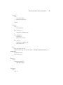
Listing 1.4: r1’s Initial Configuration
[edit]
lab@r1# show | no-more
system {
host-name r1;
time-zone America/Los_Angeles;
authentication-order [ radius password ];
Your Initial System Configuration
35
root-authentication {
encrypted-password “$1$j5nxWQ9r$p6XQ9eKqpgsGe51DYySGI/”; # SECRET-DATA
ssh-rsa “1024 65537
14507521839282798432482521835023055326381401663452058669080886491465544700784392
81114055822376198290722320666268020211763429857348456378696103199986915461962494
35479692894437417780898017483440313841107367122670080439972894195679320796753410
731222833899141869327583231170906047985814682544941905107416839803283 root”; #
SECRET-DATA
}
radius-server {
10.0.1.102 secret “$9$.fQnEhrevL”; # SECRET-DATA
}
login {
class ops {
idle-timeout 5;
permissions network;
allow-commands “show interfaces”;
deny-commands “traceroute|telnet|ssh”;
}
user lab {
uid 2000;
class superuser;
authentication {
encrypted-password “$1$nNISN$o7OGTEhEF5sOcgjS9p0Lf0”; # SECRET-DATA
}
}
user ops {
uid 2002;
class ops;
authentication {
encrypted-password “$1$SgJQQ$VYXXLPf9/TMOnb2ohWxOJ.”; # SECRET-DATA
}
}
user proctor {
uid 2001;
class superuser;
}
}
services {
ssh;
telnet;
}
36
Chapter 1
Initial Configuration and Platform Troubleshooting
syslog {
user * {
any emergency;
}
file messages {
any notice;
}
file auth {
authorization info;
archive size 5m files 5;
}
}
processes {
routing failover other-routing-engine;
}
ntp {
authentication-key 101 type md5 value “$9$fQ39SyKM87”; # SECRET-DATA
server 10.0.200.2 key 101;
trusted-key 101;
}
}
chassis {
redundancy {
routing-engine 0 master;
}
alarm {
management-ethernet {
link-down yellow;
}
}
}
interfaces {
fxp0 {
unit 0 {
family inet {
address 10.0.1.1/24;
}
}
}
}
Your Initial System Configuration
snmp {
interface fxp0.0;
community test {
clients {
10.0.200.2/32;
}
}
trap-group interface {
categories link;
targets {
10.0.200.2;
}
}
}
routing-options {
static {
route 10.0.200.0/24 {
next-hop 10.0.1.102;
no-readvertise;
}
}
}
The Case for Cut and Paste on the Exam
Time is a critical factor in the JNCIP examination, and any technique that can save time is well
worth deploying during the lab. Deciding when a configuration is common enough to warrant
pasting into the remaining routers is a decision that has to be made by each individual, and
should be based on factors such as your familiarity with using load (merge|override)
terminal, and the potential time savings that are expected. Cut and paste is a double-edged
sword, and as with any such tool, you can cause serious problems by using it incorrectly in an
effort to save time. For example, forgetting to change a lo0 address can result in duplicate
router IDs (RIDs) in a subsequent OSPF scenario, and this type of problem can be very difficult
to diagnose in the heat of battle. Generally speaking, it is advisable to paste configurations (or
particular stanzas) into a text editor such as Word Pad, where you can easily edit the variables
to suit the router that you plan to paste the configuration into.
37
Chapter 1
38
Initial Configuration and Platform Troubleshooting
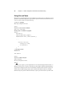
Using Cut and Paste
The following commands illustrate how an edited version of the previous configuration can be
pasted into r2. In this example, the only fields that required modification between the various
routers are the hostname and fxp0 addressing:
root@host> configure
Entering configuration mode
[edit]
lab@host# load override terminal
[Type ^D to end input]
<select paste in emulation program>
system {
host-name r2;
time-zone America/Los_Angeles;
authentication-order [ radius password ];
. . .
route 10.0.200.0/24 {
next-hop 10.0.1.102;
no-readvertise;
}
}
} <carriage return>
<control d>
load complete
[edit]
lab@host# commit and-quit
commit complete
Exiting configuration mode
lab@r2>
In the previous capture, operator input that is not echoed back is displayed in italics with “< >”
delimiters. The first such occurrence is when the user selects Paste from their terminal emulation
program after entering the load override terminal command. At the end of the capture, the
operator enters a single carriage return to place a new line after the last curly brace, and then
terminates the paste operation with the Ctrl+d key sequence (per the instructions provided at the
Your Initial System Configuration
39
beginning of the terminal paste operation). Because no errors are reported, the paste operation
appears to have been successful. You now commit the new configuration, which results in the
router’s hostname becoming r2, as highlighted.
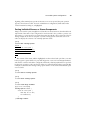
Pasting Individual Stanzas or Stanza Components
Using load override is pretty straightforward, but there are many instances when the wholesale
replacement of the entire router configuration is not desired. It is also possible to paste in complete stanzas, or components from a particular stanza, though this can be a bit tricky. The following example shows the cut and paste of just the routing-options stanza. We start on r2
where we display the contents of its routing-options stanza:
[edit]
lab@r2# show routing-options
static {
route 10.0.200.0/24 {
next-hop 10.0.1.102;
no-readvertise;
}
}
The contents of the stanza, which is highlighted, are then selected and copied into your emulation program’s capture buffer. To paste this snippet into r1, we use load merge terminal,
and must be careful to include the configuration hierarchy routing-options before performing the paste operation so the router knows where to put the information that is pasted. In this
example, we first delete the existing routing-options stanza on r1 to demonstrate that the paste
was successful:
[edit]
root@r1# delete routing-options
[edit]
root@r1# show routing-options
[edit]
root@r1# load merge terminal
[Type ^D to end input]
routing-options static {
route 10.0.200.0/24 {
next-hop 10.0.1.102;
no-readvertise;
}
}-<carriage return>
40
Chapter 1
Initial Configuration and Platform Troubleshooting
<control-d>
load complete
[edit]
root@r1# show routing-options
static {
route 10.0.200.0/24 {
next-hop 10.0.1.102;
no-readvertise;
}
}
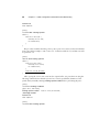
The procedure is similar when the goal is to paste a portion of a stanza, such as an individual
static route. In this example, a static route to 1.1.1.1 has been added to r2, and this route will
be pasted into r1:
[edit]
lab@r2# show routing-options
static {
route 10.0.200.0/24 {
next-hop 10.0.1.102;
no-readvertise;
}
route 1.1.1.1/32 discard;
}
After copying the 1.1.1.1 static route into the capture buffer, it is pasted into r1 using the
following commands. Note that the operator has correctly specified the destination of the
pasted data by manually entering routing-options static before performing the paste:
[edit]
root@r1# load merge terminal
[Type ^D to end input]
routing-options static route 1.1.1.1/32 discard;
/<carriage return>
<control-d>
load complete
[edit]
root@r1# show routing-options
Summary
41
static {
route 10.0.200.0/24 {
next-hop 10.0.1.102;
no-readvertise;
}
route 1.1.1.1/32 discard;
}
Summary
This chapter provided configuration and operational mode examples for a variety of initial system
configuration scenarios that are similar to the type of tasks that will confront a JNCIP candidate.
At this stage, you should have a good idea of what types of configuration tasks will confront you
as you begin your JNCIP examination, and you should now be comfortable with terminal server
use and OoB management network establishment; creating user accounts and permissions; configuring SNMP, NTP, chassis alarms, system redundancy, and syslog; and general software maintenance procedures.
42
Chapter 1
Initial Configuration and Platform Troubleshooting
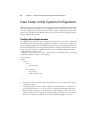
Case Study: Initial System Configuration
This section presents a list of initial system-configuration tasks that resemble the examples demonstrated throughout this chapter. For each configuration task, the relevant portions of a typical router configuration are shown and described. The complete configuration from one of the
routers is provided at the end, to illustrate a known good solution for the configuration requirements provided in the case study.
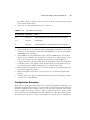
Configuration Requirements
To complete this case study, you must configure all seven routers in your test bed to comply with
the following criteria. It should take approximately 45 minutes to complete your configuration,
and you should start with a factory-fresh JUNOS software install. A reasonable approximation of
such an install will result if you load and commit the skeleton configuration found at the following
location on routers running a 5.x JUNOS software version: /packages/mnt/jbase/sbin/
install/default-juniper.conf.
Whether you opt to flash your routers, or load the skeleton configuration file, your starting
configuration should be similar to the following:
root@r1# show
system {
syslog {
user * {
any emergency;
}
file messages {
any notice;
authorization info;
}
}
}
Assign each router a hostname of the form rn, where n is a router number in the range of
1 through 7 inclusive.
Configure the fxp0 network according to Figure 1.1, and ensure that you and the proctor
station will have telnet access to all seven routers using the OoB management network.
Modify the syslog parameters to log all interactive CLI commands to a file called rn-cli,
where n is equal to the router number. Configure the CLI log to permit four archived copies
that will be no larger than 128K, and ensure that CLI-related logging is also sent to
Case Study: Initial System Configuration
43
10.0.200.2, which is providing a remote syslog service. All other syslog parameters should
be left at their default setting.
Create user accounts and permissions based on Table 1.2.
TABLE 1.2
Case Study User Accounts
User/Password
Permissions
Notes
lab
superuser
Telnet, SSH version 2 only with password, and console
root
superuser
Console only
noc
View only
Telnet, SSH version 2 only with password, and console
Ensure that all users are first authenticated through RADIUS, and that the local password
database is not automatically consulted should the RADIUS server become unreachable.
The RADIUS secret is juniper.
Allow SNMP access from all IP addresses, but only allow SNMP request over the fxp0
interface. Use a community value of public for read-only access and private for read/
write access. Send only version 1 authentication–related traps to the SNMP server.
Configure all routers as broadcast NTP clients, and authenticate all messages using MD5,
key ID 200, and key value juniper. Ensure that manual clock synchronization steps are
not required. For this example, the NTP service is provided by 10.0.1.102.
Ensure that all routers display the correct value for local time. You should assume that you
are testing in Sunnyvale, California.
Without using DNS, ensure that you can ping the proctor workstation using the name
proctor.
Configure the router to ignore management interface link status and enable the auxiliary
console port for vt100 terminals.
Configuration Examples
Each of the case study requirements will now be echoed back along with the configuration commands that would typically be used to correctly meet the operational criteria. Due to the innate
flexibility of JUNOS software, multiple solutions to the case study requirements will normally
exist; for example, the operator could opt to deploy configuration groups for common configuration elements such as the RADIUS server and authentication order. The examples shown
next attempt to show the most common and straightforward solutions to the configuration
44
Chapter 1
Initial Configuration and Platform Troubleshooting
tasks. An example of configuration group usage to support RADIUS will be provided to demonstrate this flexibility and, indirectly, to demonstrate why a JNCIP candidate is graded on
results and not on their particular configuration approach.
Assign each router a hostname of the form rn, where n is a router number in the range of
1 through 7 inclusive:
[edit]
root@host# set system host-name r2
[edit]
root@host# show system host-name
host-name r2;
Configure the fxp0 network according to Figure 1.1, and ensure that you and the proctor
station will have telnet access to all seven routers using the OoB management network:
[edit]
root@r2# set system services telnet
[edit interfaces]
root@r2# set fxp0 unit 0 family inet address 10.0.1.2/24
[edit routing-options]
root@r2# set static route 10.0.200.0/24 next-hop 10.0.1.102 no-readvertise
The resulting OoB-related configuration is now as follows:
[edit]
root@r2# show system services
telnet;
[edit]
root@r2# show interfaces fxp0
unit 0 {
family inet {
address 10.0.1.2/24;
}
}
root@r2# show routing-options
static {
route 10.0.200.0/24 {
Case Study: Initial System Configuration
45
next-hop 10.0.1.102;
no-readvertise;
}
}
Modify the syslog parameters to log all interactive CLI commands to a file called rn-cli,
where n is the router number. Configure the CLI log to permit four archived copies that will
be no larger than 128K, and ensure that CLI-related logging is also sent to 10.0.200.2,
which is providing a remote syslog service. All other syslog parameters must be left at their
default setting:
[edit system syslog]
root@r2# set file r2-cli interactive-commands any
[edit system syslog]
root@r2# set file r2-cli archive files 4
[edit system syslog]
lab@r1# set host 10.0.200.2 interactive-commands any
The modified syslog parameters are now displayed:
[edit system syslog]
lab@r1# show
user * {
any emergency;
}
host 10.0.200.2 {
interactive-commands any;
}
file messages {
any notice;
authorization info;
}
file r2-cli {
interactive-commands any;
archive files 4;
}
Create user accounts and permissions based on Table 1.3.
46
Chapter 1
TABLE 1.3
Initial Configuration and Platform Troubleshooting
Case Study User Accounts
User/pass
permissions
Notes
lab
superuser
Telnet, SSH version 2 only with password, and console
root
superuser
Console only
noc
View only
Telnet, SSH version 2 only with password, and console
The commands used to correctly configure and display user account and permission settings
are shown in Listing 1.5.
Listing 1.5: User Account Configuration
[edit system]
root@r2# set root-authentication plain-text-password
New password:
Retype new password:
[edit system login]
root@r2# set user lab class superuser
root@r2# set user lab authentication plain-text-password
New password:
Retype new password:
[edit system login]
root@r2# set class noc permissions view
[edit system login]
root@r2# set user noc class noc
[edit system login]
root@r2# set user noc authentication plain-text-password
New password:
Retype new password:
[edit]
root@r1# set system services ssh protocol-version v2
[edit]
lab@r2# set system services ssh root-login deny
Case Study: Initial System Configuration
47
[edit]
lab@r2# show system services
ssh {
root-login deny;
protocol-version v2;
}
telnet;
[edit]
root@r2# show system root-authentication
encrypted-password “$1$RTyGDGYG$ukqr37VGRgtohedSlruOk/”; # SECRET-DATA
[edit]
root@r2# show system login
class noc {
permissions view;
}
user lab {
class superuser;
authentication {
encrypted-password “$1$L6ZKKWYI$GxEI/7YzXes2JXDcHJvz7/”; # SECRET-DATA
}
}
user noc {
class noc;
authentication {
encrypted-password “$1$Z5Sb1eVg$R8.iZMCAMAOTdEeS2svvd0”; # SECRET-DATA
}
}
By default, all users except root can log in via console, telnet, or SSH. The root user can log
in by using either the console or SSH by default, so to meet the criteria for this case study you
must disable root’s ability to log in using SSH. The correct SSH version must also be set in this
example, because the default JUNOS software behavior will support SSH versions 1 and 2.
Ensure that all users are first authenticated through RADIUS, and that the local password
database is not automatically consulted should the RADIUS server become unreachable.
The RADIUS secret is juniper.
[edit system]
root@r2# set authentication-order radius
Chapter 1
48
Initial Configuration and Platform Troubleshooting
[edit system]
root@r2# set radius-server 10.0.200.2 secret juniper
The resulting system authentication configuration is now displayed:
[edit system]
root@r2# show radius-server
10.0.200.2 secret “$9$-UbYoDi.z39JG39ApREdbs”; # SECRET-DATA
[edit system]
root@r2# show authentication-order
authentication-order radius;
By omitting the password option from the system’s authentication order statement, you
ensure that the local password database is not automatically consulted when the RADIUS server
becomes unreachable, which results in the operator being prompted for a local password in the
event of RADIUS connectivity problems.
Configuration Groups
As previously mentioned, JUNOS software is extremely flexible, and this flexibility can translate
to the ability to satisfy a configuration requirement using what can appear to be orthogonal
approaches. Configuration groups provide excellent proof of this concept in that they allow
common elements of a configuration to be specified at the [edit groups] configuration hierarchy.
Once configured, these groups can then be applied to the appropriate level of the system’s configuration to affect the inheritance of group-related configuration. You can override this group
inheritance through explicit configuration where needed. For example, consider the following
configuration group called authentication, which will result in the required RADIUS and
authentication order behavior when applied as shown:
[edit]
lab@r1# show groups
authentication {
system {
authentication-order radius;
radius-server {
10.0.1.201 secret "$9$9ftBt0IylMNdsEcds24DjCtu"; # SECRET-DATA
}
}
}
Case Study: Initial System Configuration
49
[edit]
lab@r1# set system apply-groups authentication
To confirm the correct application of a configuration group, you should pipe configuration output
through the inheritance filter as shown here:
[edit]
lab@r1# show system | match radius
[edit]
lab@r1# show system | display inheritance | match radius
## 'radius' was inherited from group 'authentication'
authentication-order radius;
radius-server {
You should practice with the effects of configuration group usage before deciding to deploy the
technique on a live examination. Some candidates have been burned by failing to completely
anticipate the effects of configuration group usage. For example, the inadvertent configuration
(and operation) of an IGP on your fxp0 OoB management interface (which is never a good idea)
can easily result when a configuration group is used to add protocol families to your interfaces
in conjunction with a command such as set protocol isis interface all.
Allow SNMP access from all IP addresses, but only allow SNMP request over the fxp0
interface. Use a community value of public for read-only access and private for read/
write access. Send only version 1 authentication–related traps to the SNMP server:
[edit snmp]
root@r2# set interface fxp0
[edit snmp]
root@r2# set community public
[edit snmp]
root@r2# set trap-group foo categories authentication
[edit snmp]
root@r2# set trap-group foo targets 10.0.200.2
[edit snmp]
root@r2# set community private authorization read-write
50
Chapter 1
Initial Configuration and Platform Troubleshooting
The resulting configuration changes are now confirmed:
[edit snmp]
root@r2# show
interface fxp0.0;
community public;
community private {
authorization read-write;
}
trap-group foo {
version v1;
categories authentication;
targets {
10.0.200.2;
}
}
By including interface fxp0, you disallow access from all other interfaces. The lack of a
client statement results in the default of access being allowed from all clients. The default for
SNMP traps is to send both version 1 and version 2, so version 1 traps must be specified.
Configure your routers as broadcast NTP clients, and authenticate all messages using
MD5, key ID 200, key value juniper. Ensure that manual clock synchronization steps are
not required. For this example, you may assume that the NTP service is provided by
10.0.1.102:
[edit system ntp]
root@r2# set authentication-key 200 type md5 value juniper
[edit system ntp]
root@r2# set trusted-key 200
[edit system ntp]
root@r2# set broadcast-client
[edit system ntp]
root@r2# set boot-server 10.0.1.102
Once again, the changes to the configuration are confirmed:
[edit system ntp]
root@r2# show
boot-server 10.0.1.102;
Case Study: Initial System Configuration
51
authentication-key 200 type md5 value “$9$KoAWX-YgJHqfVwqfTzCAvWL”; # SECRET-DATA
broadcast-client;
trusted-key 200;
Because manual synchronization is not permitted in this example, you must include the
boot-server statement to allow initial clock synchronization at boot. You must also configure
your router as a broadcast client to tell it to listen to NTP broadcasts. If all goes according to
plan, you should have NTP associations like the following example on all your routers after
they are rebooted; it should be noted that the server type (t) is now set to broadcast (b):
root@r1> show ntp associations
remote
refid
st t when poll reach
delay
offset jitter
==============================================================================
*10.0.1.102
LOCAL(1)
11 b
64 377
0.000
39.204
1.045
Ensure that all routers display the correct value for local time. You should assume that you
are testing in Sunnyvale, California:
[edit system]
root@r2# set time-zone America/Los_Angeles
There is no CLI option for America/Sunnyvale, but Los Angeles and the San Francisco Bay
Area are both on Pacific Time so this does the trick.
Without using DNS, ensure that you can ping the proctor workstation using the name
proctor.
You must configure a static host mapping to accomplish this task because DNS services are
not available in this example:
[edit system]
lab@r2# set static-host-mapping proctor inet 10.0.200.1
Configure the router to ignore management interface link status and enable the auxiliary
console port for vt100 terminals.
[edit chassis alarm]
lab@r2# set management-ethernet link-down ignore
[edit system ports]
lab@r2# set auxiliary type vt100
The Completed Case Study Configuration
The configuration of r2 is shown in Listing 1.6. This configuration satisfies all case study
requirements.
52
Chapter 1
Initial Configuration and Platform Troubleshooting
Listing 1.6: Case Study Configuration for r2
[edit]
lab@r2# show | no-more
version 5.2R2.3;
system {
host-name r2;
time-zone America/Los_Angeles;
authentication-order radius;
ports {
auxiliary type vt100;
}
root-authentication {
encrypted-password “$1$RTyGDGYG$ukqr37VGRgtohedSlruOk/”; # SECRET-DATA
}
radius-server {
10.0.200.2 secret “$9$-UbYoDi.z39JG39ApREdbs”; # SECRET-DATA
}
login {
class noc {
permissions view;
}
user lab {
uid 2000;
class superuser;
authentication {
encrypted-password “$1$L6ZKKWYI$GxEI/7YzXes2JXDcHJvz7/”; #
SECRET-DATA
}
}
user noc {
uid 2001;
class noc;
authentication {
encrypted-password “$1$Z5Sb1eVg$R8.iZMCAMAOTdEeS2svvd0”; #
SECRET-DATA
}
}
}
static-host-mapping {
proctor inet 10.0.200.1;
}
Case Study: Initial System Configuration
services {
ssh {
root-login deny;
protocol-version v2;
}
telnet;
}
syslog {
user * {
any emergency;
}
host 10.0.200.2 {
interactive-commands any;
}
file messages {
any notice;
authorization info;
}
file r2-cli {
interactive-commands any;
archive files 4;
}
}
ntp {
boot-server 10.0.1.102;
authentication-key 200 type md5 value “$9$KoAWX-YgJHqfVwqfTzCAvWL”; #
SECRET-DATA
broadcast-client;
trusted-key 200;
}
}
chassis {
alarm {
management-ethernet {
link-down ignore;
}
}
}
interfaces {
fxp0 {
unit 0 {
53
Chapter 1
54
Initial Configuration and Platform Troubleshooting
family inet {
address 10.0.1.2/24;
}
}
}
}
snmp {
interface fxp0.0;
community public;
community private {
authorization read-write;
}
trap-group foo {
version v1;
categories authentication;
targets {
10.0.200.2;
}
}
}
routing-options {
static {
route 10.0.200.0/24 next-hop 10.0.1.102;
}
}
You should now ensure that the remaining routers in your test bed have a similar initial system
configuration. The use of cut and paste using load override terminal is recommended as a
time-saving technique. You should attempt to validate as much of your initial configuration as
possible using the techniques demonstrated in this chapter because “silly” mistakes such as fatfingering the IP address associated with the proctor subnet are hard to spot when simply viewing the router’s configuration.
Spot the Issues: Review Questions
55
Spot the Issues: Review Questions
1.
Will the following login class provide superuser privileges while preventing the user’s ability to
enter the configuration mode?
[edit system login]
lab@t1# show class test
permissions all;
deny-commands “^config$”;
2.
Will this syslog configuration alter the default size of the messages file?
[edit system syslog]
lab@t1# show
archive size 10m files 5;
user * {
any emergency;
}
file messages {
any notice;
authorization info;
archive size 128m files 10;
}
file r1-cli {
interactive-commands any;
archive files 5;
}
3.
You must ensure that your router’s cold start trap is sent to a non–directly attached SNMP
server. What command is needed?
4.
Your router is not synchronizing with the NTP server after a reboot. What could be wrong with
this NTP configuration? (You may assume that the secret is correctly configured.)
lab@t1# show system ntp
boot-server 10.0.1.201;
authentication-key 10 type md5 value “$9$2XoJDn6AIEy”; # SECRET-DATA
server 10.0.1.201 key 10 version 3; # SECRET-DATA
56
5.
Chapter 1
Initial Configuration and Platform Troubleshooting
How can you configure an M-series router to source all SNMP trap messages from its lo0 interface without affecting the source addresses of other traffic?
[edit]
lab@r4# show snmp
community public {
clients {
0.0.0.0/0 restrict;
10.0.1.102/32;
}
}
trap-options {
source-address lo0;
}
Spot the Issues: Answers
57
Spot the Issues: Answers
1.
No. The deny-commands regular expression incorrectly matches on the exact sequence
config, which is not a valid command. A user in this class would still be able to use the
configure command. The correct regular expression would be ^configure$.
2.
Yes. The global syslog archive parameters have been set to retain five 10MB files, and the operator’s attempt at returning the messages file archive settings to the default setting of ten 128KB
files has failed due to incorrect use of the Mega (m) suffix.
3.
You will need to use the backup-router statement with the correct gateway address. The
backup-router is used while the system is booting, and in the event that the routing daemon
cannot be started.
4.
The NTP configuration is missing the trusted-key definition. Without a list of trusted keys, the
router will not use, or accept, key-id 10 in NTP messages.
5.
You must use the source-address option at the [edit snmp trap-options] hierarchy when
configuring SNMP. Use of default-address-selection at the [edit system] hierarchy
affects all locally generated packets, not just SNMP.