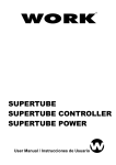
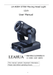
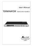
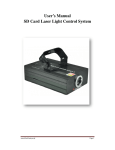
1
DMX controller for LED Tube
DMX CONTROLLER FOR LED TUBE
User Manual
www.flash-butrym.pl
1
DMX controller for LED Tube
Led controller can be controlled by DMX 512 console. Our LED color changing tube / wall combined with
the controller makes colorful and dynamic light scenery effects. It is widely applied to entertainment hall,
stage, social club and outdoor building decoration.
A: Specification:
3. Weight: 1.14 kg
4. Size: 210×125.2×44.2(mm)
5. Communication mode: Proprietary data protocol/DMX-512
6. Power input: DC9V-12V/500 mA
7. 4-pin female connector for signal output
8. 3-pin connector for DMX512 connection
9. 1000 separate DMX addressing for each channel
B:MODE/SETUP/UP/DOWN four function sets
1. Press “MODE” button to adjust accordingly
BLACK, STATIC RED, STATIC GREEN, STATIC YELLOW, STATIC BLUE, STATIC PURPLE,
STATIC CYAN, STATIC WHITE, COLOR CHANGE, SLOW FLOW 1,SLOW FLOW 2,ROLL CHASE
1, ROLL CHASE 2, MULIT COLOR, FAST FLOW 1,FAST FLOW 2, 2 COLOR CHASE, 2 COLOR
FLOW, COLOR FADE, AUTO RUN, SYSTEM MODE
2. Press “SETUP” button to adjust accordingly
R××G××B×× Select“R”“G”“B”Dimming by pressing“UP”、“DOWN”key.
RUN SPEED: 1-100
FLASH FREQ: 1-100
COLOR SORT: select 2 COLOR FLOW or 2 COLOR CHASE (range: 0-20)
UNIT TIMES: running times for each type of display under auto-run mode
SET ADDRESS: [YES] : Please set sequential addressing for all color-changing tube/wall light
(Reset address while startup for the first time, amended array order, and quantity minus or
plus so as to get correct display) The addressing would be stored in color-changing
tube/wall light once it is set
● address-setting method for sort order connection
First set start- address as “1”, then set color-changing /wall address
● address-setting method for bus connection
Every branch should be set its separate address.
For example:
1st branch: Set the start- address “1”
2nd branch: set the start- address value equitable to “ tube/wall light amount for the first
branch”
3rd branch: set the start-address value equitable to “ tube/wall light amount for the first
branch and the second branch”
[NO]: no address
DMX Channel: [0]: No DMX controlling, controlled by keyboard
[1-512]: controlled by DMX, the starting channel as its value
TUBE AMOUNT: tube/wall light controller amount setting (1-1000 pcs, 1M/1 pcs)
For example:
One DMX controller control 2 pcs led controller. Set the first controller’s DMX address
value as “1”, it would occupy 1-4 channel, then the second one’s DMX address value
should be set as “5”, and it would occupy 5-8 channel.
3. UP: plus parameter
4. Down: minus parameter
5. Enter DMX mode with DMX signal and receive 4 channel DMX signals, adjust the starting address
www.flash-butrym.pl
2
DMX controller for LED Tube
(1-512) by pressing “ UP” or “ DOWN” button.
1>: The first channel(0~11) can control output for Red, Green and Blue
The second DMX channel control output for red ;
0
darker
255
brighter
The third DMX channel control output for Green ;
0
darker
255
brighter
The fourth DMX channel control output for Blue :
0
255
darker brighter
2>: The first channel (12-255) can control 20 types of displays as below;
11-23: BLACK
132-143: SLOW FLOW 2
24-35: RED
36-47: GREEN
48-59: YELLOW
60-71: BLUE
72-83: PURPLE
84-95: CYAN
96-107: WHITE
108-119: COLOR CHANGE
144-155: ROLL CHASE 1
156-167: ROLL CHASE 2
168-179: MULTI COLOR
180-191: FAST FLOW 1
192-203: FAST FLOW 2
204-215: 2 COLOR CHASE
216-227: 2 COLOR FLOW
228-239: COLOR FADE
120-131: SLOW FLOW
240-255: AUTO RUN
The second DMX channel(0-255)controls speed
0: 1 step/min
255: 100 steps/sec
The third DMX channel(0-255) controls flash frequency
0: 1 Hz
255: 20 Hz
The fourth DMX channel (0-255) selects “ 2 color flow” or “ 2 color chase “
0-11: red + green
12-23:red+ yellow
24-35: red + blue
36-47: red+ purple
48-59: red+ cyan
132-143: yellow + blue
144-155: yellow+ purple
156-167: yellow +cyan
168-179: yellow + white
180-191: blue+ purple
60-71: red+ white
72-83: green+ yellow
84-95: green + blue
96-107:green+ purple
108-119: green+ cyan
120-131: green+ white
192-203: blue + cyan
204-215: blue+ white
216-227: purple+ cyan
228-239: purple+ white
240-255: cyan+ white
www.flash-butrym.pl
3
DMX controller for LED Tube
C: led controller function structure
Front plant
Rear plant
A) Power switch
B) - Minus
C) + Plus
D) Function set
E) Selectable display mode
F) LCD screen
G) DMX512 signal output
H) DMX512 signal input
I) Color-changing tube/ wall light signal output
J) Power input (DC 9V- 12V)
www.flash-butrym.pl
4
DMX controller for LED Tube
D: Electrical Connection diagram
Plug----2pin female plug spigot
Description:
•
Connect the first color-changing tube with led controller signal connector and put it through, the
following color-changing tubes are to be connected with power supply in order;
•
The signal amplifier must be used every other 60 pcs of color-changing tubes, the signal between
60X and 60X+1 (X stands for natural number) should be enhanced by the amplifier;
•
The 90Xth color-changing tube( X stands for natural number) must be reconnected with power
supply (100V-240V) and the power output should be stopped by P3. The power (240V/50Hz) and
signal output connector for the last tube should be stopped by Teminator (1 pc 120Ω resistor inside)
in order to prevent water. Each group of circuit can be connected with 1000 pcs color-changing tube
(All disconnected interface should be connected with waterproof spigot, and all-joints
should be used sealants)
www.flash-butrym.pl
5