1
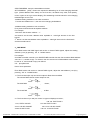
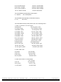
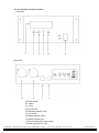
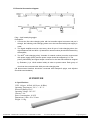
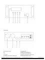
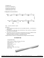
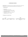
SUPERTUBE
SUPERTUBE CONTROLLER
SUPERTUBE POWER
User Manual / Instrucciones de Usuario
USER MANUAL
SUPERTUBE CONTROLLER
PAGE 1
SUPERTUBE
PAGE 5
SUPERTUBE POWER
PAGE 6
MANUAL DE USUARIO
SUPERTUBE CONTROLLER
PAGE 7
SUPERTUBE
PAGE 11
SUPERTUBE POWER
PAGE 12
This symbol on the product or on its packaging indicates that this product
shall not be trated as household waste. Instead it shall be handed over to
the applicable collection point for the recycling of electrical an electronic
equipment. By ensuring this product is disposed of correctly, you will help
prevent potential negative consequences for the environment and human
health, which could otherwise be caused by inappropriate waste handling
of this product. The recycling of amterials will help to conserve natural
resources. For more detailed information sabout recycling of this product,
please contact your local city office, your household waste disposal service
or the shop where you purchased the product.
Este símbolo en su equipo o embalaje, indica que el presente producto
no puede ser tratado como residuos domésticos normales, sino que deben
entregarse en el correspondiente punto de recogida de equipos electrónicos
y eléctricos. Asegurándose de que este producto es desechado
correctamente, Ud. está ayudando a prevenir las consecuencias negativas
para el medio ambiente y la salud humana que podrían derivarse de la
incorrecta manipulación de este producto. EL reciclaje de materiales
ayuda a conservar las reservas naturales. Para recibir más información,
sobre el reciclaje de este producto, contacte con su ayuntamiento, su
punto de recogida más cercano o el distribuidor donde adquirió el producto.
SUPERTUBE CONTROLLER
Led controller can be controlled by DMX 512 console. Our LED color changing tube
combined with the controller makes colorful and dynamic light scenery effects. It is widely
applied to entertainment hall, stage, social club and outdoor building decoration.
A: Specification:
1. Weight: 1.14 kg
2.
Size: 210×125.2×44.2(mm)
3.
Communication mode: Proprietary data protocol/DMX-512
4.
Power input: DC9V-12V/500 mA
5.
4-pin female connector for signal output
6.
3-pin connector for DMX512 connection
7.
1000 separate DMX addressing for each channel
B:MODE/SETUP/UP/DOWN four function sets
1. Press “MODE” button to adjust running modes accordingly. there are three running modes:
DMX mode, system setup mode, running built-in programs mode.
2. Press “SETUP” button to adjust accordingly
Move curser, Press “SETUP” button to set up the current mode, then change the
parameter of this mode by “UP” and “down” buttons.
3. Press “ UP “ button to increase the number of the parameter under the curser.
4. Press “down “ button to reduce the number of the parameter under the curser.
C: OPERATION
1.
.The built-in programs are as follows:
DIMMER, STATIC COLOR, COLOR CHANGE, SLOW FLOW 1,SLOW FLOW 2,ROLL
CHASE 1, ROLL CHASE 2, MULIT COLOR, FAST FLOW 1,FAST FLOW 2, 2 COLOR
CHASE, 2 COLOR FLOW, COLOR FADE,TU BE CHASE1, TUBE CHASE2, AUTO RUN,
When running built-in programs mode, press “SETUP” button to move the curser, then change
the parameter under the curser by “up” and “down” buttons.
a:
R:0~255 G:0~255 B:0~255 RGB dimmer
a:
SP: 1-100
RUN SPEED
b:
FS: 1-100
FLASH FREQ
c:
d:
when STATIC COLOR, you choose one color, there are 8 color sorts including black
when
2 COLOR FLOW and 2 COLOR CHASE, you can choose 2 color combination,
there are 28 color combination sorts.
e:when TUBE CHASE1 and TUBE CHASE2, you can choose color, there are 7 color sorts.
f: FREQUENCY: running times for each type of display under auto-run mode
2,
, system setup mode,
TUBE NUMBER: (set up the quantity of tubes)tube/wall light controller amount setting (1-1000
pcs,1M/1 pcs)
SUPERTUBE - SUPERTUBE CONTROLLER - SUPERTUBE POWER
User Manual/Manual de Usuario
Page/Página 1
START ADDRESS: set up the start address of tubes.
SET ADDRESS: [YES] : Please set sequential addressing for all color-changing tube/wall
light
(Reset address while startup for the first time, amended array order, and quantity
minus or plus so as to get correct display) The addressing would be stored in color-changing
tube/wall light once it is set
● address-setting method for sort order connection
First set start- address as “1”, then set color-changing /wall address
● address-setting method for bus connection
Every branch should be set its separate address.
For example:
1st branch: Set the start- address “ 1”
2nd branch: set the start- address value equitable to “ tube light amount for the first
branch”
3rd branch: set the start-address value equitable to “ tube light amount for the first branch
and the second branch”
3、
、DMX MODE
Enter DMX mode with DMX signal and receive 4 channel DMX signals, adjust the starting
address (1-512) by pressing UP or DOWN button.
For example:
One DMX controller controls 2 pcs SUPERTUBE controller. Set the first controllers DMX address
value as “1”, it would occupy 1-4 channel, then the second one´s DMX address value should
be set as “5”, and it would occupy 5-8 channel
UP:
plus parameter
Down: minus parameter
Enter DMX mode and receive 4 channel DMX signals, adjust the start address (1-512) by
pressing “ UP” or “ DOWN” button
1>: The first channel(0~16) can control output for Red, Green and Blue
The second DMX channel control output for red ;
0
255
darker
brighter
The third DMX channel control output for Green ;
0
255
darker
brighter
The fourth DMX channel control output for Blue :
0
darker
255
brighter
2>: The first channel (17-255) can control 15 types of displays as below;
128-143: FAST FLOW 1
17-31, STATIC COLOR
144-159: FAST FLOW 2
32-47: COLOR CHANGE
48-63: SLOW FLOW 1
SUPERTUBE - SUPERTUBE CONTROLLER - SUPERTUBE POWER
160-175: 2 COLOR CHASE
176-191: 2 COLOR FLOW
User Manual/Manual de Usuario
Page/Página 2
64-79: SLOW FLOW 2
192-207: COLOR FADE
80-95: ROLL CHASE 1
208-223: TUBE CHASE1
96-111: ROLL CHASE 2
224-239: TUBE CHASE2
112-127: MULTI COLOR
240-255: AUTO RUN
The second DMX channel(0-255) controls speed
0: 1 step/min
255: 100 steps/sec
The third DMX channel(0-255) controls flash frequency
0: 1 Hz
255: 20 Hz
The fourth DMX channel (0-255) selects color sort in following cases:
1> when “2 color flow” or “2 color chase”
0-8:black+red
9-17:black+ green
18-26:black+ yellow
27-35:black+ blue
36-44:black+ purple
126-134: green + blue
135-143:green+ purple
144-152: green+ cyan
153-161: green+ white
162-170: yellow + blue
46-53:black+ cyan
171-179: yellow+ purple
54-62:black+ white
180-188: yellow +cyan
63-71: red + green
189-197: yellow + white
72-80:red+ yellow
198-206: blue+ purple
81-89: red + blue
207-215: blue + cyan
90-98:red+purple
99-107: red+ cyan
108-116: red+ white
117-125: green+ yellow
216-224:blue+white
225-233: purple+ cyan
234-242: purple+ white
243-255: cyan+ white
2> when “static color”
0-31:black
128-159: blue
32-63: red
160-191:purple
64-95: green
96-127: yellow
192-223: cyan
224-255: white
3> when “tube chase1” or “tube chase2”
107-142: blue
0-35: red
143-178:purple
36-70: green
179-214: cyan
71-106: yellow
215-255: white
SUPERTUBE - SUPERTUBE CONTROLLER - SUPERTUBE POWER
User Manual/Manual de Usuario
Page/Página 3
D: led controller function structure
Front plant
Rear plant
A) Power switch
B) - Minus
C) + Plus
D) Function set
E) Selectable display mode
F) LCD screen
G) DMX512 signal output
H) DMX512 signal input
I) Color-changing tube signal output
J) Power input (DC 9V- 12V)
SUPERTUBE - SUPERTUBE CONTROLLER - SUPERTUBE POWER
User Manual/Manual de Usuario
Page/Página 4
E: Electrical Connection diagram
Plug----2pin female plug spigot
Description:
1. Connect the first color-changing tube with led controller signal connector and put it
through, the following color-changing tubes are to be connected with power supply in
order;
2. The signal amplifier must be used every other 60 pcs of color-changing tubes, the
signal between 60X and 60X+1 (X stands for natural number) should be enhanced by
the amplifier;
3. The 90Xth color-changing tube( X stands for natural number) must be reconnected
with power supply (240V) and the power output should be stopped by P3. The
power (240V/50Hz) and signal output connector for the last tube should be stopped
by Teminator (1 pc 120 Ω resistor inside) in order to prevent water. Each group of
circuit can be connected with 1000 pcs color-changing tube
(All disconnected interface should be connected with waterproof spigot, and all-joints
should be used sealants)
SUPERTUBE
A: Specifications:
LED: 144 pcs ( 48 Red, 48 Green, 48 Blue)
Operating Temperature: -20 º C + 45 º C
Protection Rating: IP 65
Operating Voltage: DC 12V
Current: 1.4 A
Power Consumption: 16.8 W
Dimensions: 1000 x 50 x 25 mm
Weight: 1.0 Kg.
SUPERTUBE - SUPERTUBE CONTROLLER - SUPERTUBE POWER
User Manual/Manual de Usuario
Page/Página 5
SUPERTUBE POWER
Supertube Power is designed to enhance the power and amplify the deteriorating or distorted
signal. One Supertube power should be used every other 8pcs of 12V LED multi color
changing tube linked in series.
A: Specification:
1.
2.
3.
4.
5.
6.
weight: 1.9kgs
size: 29.4x11.7x5.1cm
4-pin male connector for signal in
4-pin female connector for signal out
power in: AC 240V
power out:2-pin female connector, DC 12V
7. operating temperature:-20ºC~40ºC
B. Electrical Connection Diagram.
SUPERTUBE
POWER
SUPERTUBE
POWER
CONTROLLER
POWER
POWER
SUPERTUBE - SUPERTUBE CONTROLLER - SUPERTUBE POWER
User Manual/Manual de Usuario
Page/Página 6
SUPERTUBE CONTROLLER
Este controlador de LEDs puede ser controlado con una consola DMX 512. El tubo
cambia-color combinado con el controlador, es capaz de crear efectos de luz dinámicos y
coloridos. Tiene un amplio número de aplicaciones en salas, escenarios, clubs sociales o
decoraciones al aire libre.
A: Especificaciones:
1. Peso 1.14 kg
2. Tamaño : 210×125.2×44.2(mm)
3. Modo de comunicación: Protocolo DMX 512
4. Alimentación: DC9V-12V/500 mA
5. Conector hembra de 4 pines para salida de señal
6. Conector de 3 pines para el conexionado DMX
7. 1000 direccionamientos DMX separados para cada canal
B:MODE/SETUP/UP/DOWN configuración de las cuatro funciones
1. Presione el botón “MODE” para ajustar los modos de ejecución. Hay 3 modos: DMX,
System Setup y programas incorporados.
2. Presione “SETUP” para ajustar a su elección.
Mueva el cursor, presione “SETUP” para configurar el modo, entonces cambie los
parámetros de ese modo con las teclas “UP” y “DOWN”.
3. Presione “UP” para incrementar el valor del parámetro en curso
4. Presione “DOWN” para rojoucir el valor del parámetro en curso
C: FUNCIONAMIENTO
1.
.Los programas incorporados son:
DIMMER, STATIC COLOR, COLOR CHANGE, SLOW FLOW 1,SLOW FLOW
2,ROLL CHASE 1, ROLL CHASE 2, MULTI COLOR, FAST FLOW 1,FAST FLOW 2, 2
COLOR CHASE, 2 COLOR FLOW, COLOR FADE,TUBE CHASE1, TUBE CHASE2,
AUTO RUN,
Cuando ejecute los programas incorporados, presione la tecla “SETUP” para mover
el cursor, entonces cambia el parámetro del modo en curso con las teclas “UP”,
“DOWN”.
a: R:0~255 G:0~255 B:0~255 RGB dimmer
a: SP: 1-100 VELOCIDAD DE EJECUCION
b: FS: 1-100 FRECUENCIA DE FLASH
c:
En color STATIC, puede elegir un color, hay 8 incluyendo el negro.
d: en 2 COLOR FLOW y 2 COLOR CHASE, puede elegir la combinación de dos
colores, hay 28 combinaciones de color posibles.
e: En modo TUBE CHASE 1 y TUBE CHASE 2, puede elegir color de entre 7
variaciones
f: FREQUENCY: Veces que se ejecuta pa ra cada tipo de visualización en modo
auto-run.
SUPERTUBE - SUPERTUBE CONTROLLER - SUPERTUBE POWER
User Manual/Manual de Usuario
Page/Página 7
2.,
, Modo System Setup,
TUBE NUMBER: (Configura la cantidad de tubos) (1-1000 piezas,1M/1 pieza)
START ADDRESS: Configura la dirección de inicio de los tubos
SET ADDRESS: [YES] : Configure la sec uencia de inicio para todos los tubos
cambia-color (Reinicie la dirección cuando inicia por vez primera, corrigiendo el orden y
la cantidad en menos o más hasta conseguir el efecto correcto ) La dirección debe ser
almacenada una vez configurada.
● Configurando la dirección por orden de conexión
Configure la primera unidad como “ 1”
● Configurando la dirección por bus de conexión
Cada “rama” debe ser configurada con dirección separada.
Por ejemplo:
1ª rama: Se configure la dirección de inicio en “ 1”
2ª rama: Se configure a un valor equitativo a la dirección de la primera salida
3ª rama: Se configure a un valor equitativo a la dirección de la segunda salida
3、
、MODO DMX
Al introducir señal DMX, la unidad ocupará 4 canales de control DMX, ajuste la dirección
de inicio (1-512) presionando las teclas “UP” y “DOWN”.
Por ejemplo:
Una mesa DMX controla dos controladores de tubos. Configure el primero controlador
con la dirección DMX “1” que usa los canales 1-4, entonces el segundo controlador se
configura a la dirección “5” para ocupar los canales 5-8.
UP: Incrementa el valor del parámetro
DOWN: Reduce el valor del parámetro
Introduzca el modo de control DMX para ocupar 4 canales DMX, ajusta la dirección de
inicio (1-512) presionando las teclas “UP” y “DOWN”.
1>: El primer canal (0~16) puede controlar la salida de Rojo, Verde y Azul.
El Segundo canal DMX controla la salida del color ROJO
0
255
oscuro
claro
El Tercer canal DMX controla la salida del color VERDE
0
255
oscuro
claro
El Cuarto canal DMX controla la salida del color AZUL
0
oscuro
255
claro
2>: El primer canal (17-255) puede controlar hasta 15 tipos de dibujos;
17-31, STATIC COLOR
32-47: COLOR CHANGE
48-63: SLOW FLOW 1
64-79: SLOW FLOW 2
128-143: FAST FLOW 1
144-159: FAST FLOW 2
160-175: 2 COLOR CHASE
176-191: 2 COLOR FLOW
192-207: COLOR FADE
SUPERTUBE - SUPERTUBE CONTROLLER - SUPERTUBE POWER
User Manual/Manual de Usuario
Page/Página 8
80-95: ROLL CHASE 1
96-111: ROLL CHASE 2
112-127: MULTI COLOR
208-223: TUBE CHASE1
224-239: TUBE CHASE2
240-255: AUTO RUN
El Segundo canal (0-255) controla la velocidad
0: 1 paso/minuto
255: 100 pasos/segundo
El tercer canal (0-255) controla la frecuencia de Flash
0: 1 Hz
255: 20 Hz
El cuarto canal (0-255) seleccciona la clase de color de entre los siguientes casos:
1> Cuando se elige “ 2 color flow” o “2 color chase”
0-8:negro + rojo
126-134: verde + azul
9-17:negro + verde
135-143:verde + púrpura
18-26:negro + amarillo
144-152: verde + cyan
27-35: negro + azul
153-161: verde + blanco
162-170: amarillo + azul
36-44:negro + púrpura
46-53:negro+ cyan
54-62:negro+ blanco
63-71: rojo + verde
72-80:rojo+ amarillo
81-89: rojo + azul
90-98: rojo+ púrpura
99-107: rojo+ cyan
108-116: rojo+ blanco
117-125: verde+ amarillo
2> Al elegir “static color”
0-31:negro
32-63: rojo
64-95: verde
96-127: amarillo
171-179: amarillo+ púrpura
180-188: amarillo +cyan
189-197: amarillo + blanco
198-206: azul+ púrpura
207-215: azul + cyan
216-224: azul+ blanco
225-233: púrpura+ cyan
234-242: púrpura+ blanco
243-255: cyan+ blanco
128-159: azul
160-191:púrpura
192-223: cyan
224-255: blanco
3>Al elegir “tube chase1” o “tube chase2”
107-142: azul
0-35: rojo
36-70: verde
71-106: amarillo
143-178:púrpura
179-214: cyan
215-255: blanco
D: TECLAS DE FUNCION Y CONTROLES
Vista Frontal
SUPERTUBE - SUPERTUBE CONTROLLER - SUPERTUBE POWER
User Manual/Manual de Usuario
Page/Página 9
Vista trasera
A) Interruptor de red
B) C) +
D) Funcion
E) Selector de modo de visualización
SUPERTUBE - SUPERTUBE CONTROLLER - SUPERTUBE POWER
F) Pantalla LCD
G) Salida de señal DMX 512
H) Entrada de señal DMX 512
I) Salida de señal al tubo cambia color
J) Alimentación (DC 9V- 12V)
User Manual/Manual de Usuario
Page/Página 10
F) Pantalla LCD
G) Salida de señal DMX 512
H) Entrada de señal DMX 512
I) Salida al tubo cambia color
J) Alimentación (DC 9V- 12V)
E: Diagrama de conexión eléctrica
Plug---- Conector hembra de 2 pines
Descripción:
1. Conecte el primer tubo cambia-color con el controlador de señal , y a continuación el
siguiente tubo.
2. El amplificador de señal debe usarse cada 60 tubos. Entre este tubo y el siguiente
debe colocarse el amplificador.
3. Cada 90 tubos, debe ser reconectado a la alimentación (240 V AC) la salida de señal
del último tubo debe ser cerrada con una resistencia de 120 ohmios.
Cada grupo puede ser conectado con 1000 tubos de color.
Cualquier toma de conexión no conectada debe ser protegida contra la intemperie)
SUPERTUBE
A: Especificaciones:
LEDs: 144 pcs ( 48 Rojos, 48 Verdes, 48 Azules)
Temperatura de uso: -20 º C + 45 º C
Grado IP: IP 65
Alimentación: DC 12V
Corriente: 1.4 A
Consumo: 16.8 W
Dimensiones: 1000 x 50 x 25 mm
Peso: 1.0 Kg.
SUPERTUBE - SUPERTUBE CONTROLLER - SUPERTUBE POWER
User Manual/Manual de Usuario
Page/Página 11
SUPERTUBE POWER
Supertube Power está diseñado para realzar y amplificar la señal deteriorada o distorsionada.
Un Supertube Power debe ser usado cada 8 tubos cambia color conectados en serie.
A. Especificaciones:
1.
2.
3.
4.
5.
6.
Peso: 1.9kgs
Dimensiones: 29.4x11.7x5.1cm
Conector macho 4 pin para la señal de entrada
Conector hembra de 4 pin para la señal de salida
Alimentación: AC 240V
Alimentación :Conector hembra 2 pin DC 12V
7. Temperatura de uso:-20 ºC~40ºC
B. Diagrama de conexión eléctrica.
SUPERTUBE
POWER
SUPERTUBE
POWER
CONTROLLER
POWER
POWER
SUPERTUBE - SUPERTUBE CONTROLLER - SUPERTUBE POWER
User Manual/Manual de Usuario
Page/Página 12
Equipson, S.A.
www.equipson.es
[email protected]