1
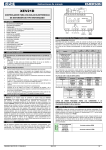
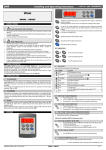
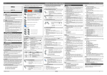
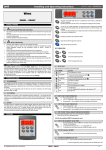
dIXEL SET: XJP40D Displaying and modify SET POINT: by pressing and releasing the key, the instrument displays value of set-point for 5 seconds. By pressing and holding this button at least for 3 seconds you can modify the SET value. SECTION: Section menu access: by pressing and releasing this key you enter in section menu. One instrument can have up to 4 section (par. 1). ACQUISITION MODULE COPY: CONTENT 1. 2. 3. 4. 5. 6. 7. 8. 9. 10. 11. 12. 13. 1592010250 Operating Instructions General warning _____________________________________________________ 1 General description ___________________________________________________ 1 Programming keyboard (KB1 PRG) ______________________________________ 1 Main functions _______________________________________________________ 1 Parameters programming for section _____________________________________ 2 Alarm management ___________________________________________________ 2 X-REP & KB1 PRG & HOT KEY _________________________________________ 2 Installation and mounting_______________________________________________ 2 Electrical connections _________________________________________________ 3 Serial communications ________________________________________________ 3 Technical data _______________________________________________________ 3 WIRING Connections _________________________________________________ 3 Default values _______________________________________________________ 3 It permits to copy total configuration of one section into another section. During normal operation it allows the data upload from module to “Hot Key”. 3.1 ABOUT LED The display always shows the active section, either via remote keyboard or via the XREP. There are three different colour LEDs, in the following table are presented the states it can be displayed: LED Yellow Yellow Yellow Green Red 1. GENERAL WARNING State of Led Blink ON OFF ON ON Function RX/TX in progress The module receive but not transmit It’s absent the serial communication Power supply is present Alarm N.B: Section 7.1. : LEDs states displayed during Hot Key usage. 1.1 • • • 1.2 • • • • • • • • PLEASE READ BEFORE USING THIS MANUAL 4. MAIN FUNCTIONS The instrument is provided with two type of parameters map: The global parameters map The section parameters map Modification of global parameters map influence all active sections, while every section has one independent section map. Through “Section” button you can modify the global section parameters, while with “Prg” button you can modify the specific section parameters. This manual is part of the product and should be kept near the instrument for easy and quick reference. The instrument shall not be used for purposes different from those described hereunder. It cannot be used as a safety device. Check the application limits before proceeding. SAFETY PRECAUTIONS Check the supply voltage is correct before connecting the instrument. Do not expose to water or moisture: use the controller only within the operating limits avoiding sudden temperature changes with high atmospheric humidity to prevent formation of condensation Warning: disconnect all electrical connections before any kind of maintenance. Fit the probe where it is not accessible by the End User. The instrument must not be opened. In case of failure or faulty operation send the instrument back to the distributor or to “Dixell S.p.a.” (see address) with a detailed description of the fault. Consider the maximum current which can be applied to each relay (see Technical Data). Ensure that the wires for probes, loads and the power supply are separated and far enough from each other, without crossing or intertwining. In case of applications in industrial environments, the use of mains filters (our mod. FT1) in parallel with inductive loads could be useful. Global menu - “SECTION” Key The “Section” key allows the sections administration (up to four sections) in which the instrument can be divided, moreover it’s possible to display the measured value from input of active section. With “Section” it’s possible to modify the number of sections and the parameters of global map. In the following table there is the complete list of labels of global menu: Label Snc SE# Pr1 out Where with SE# indication it’s intended that if there are four active sections, on global menu we will have 4 labels: SE0, SE1, SE2, SE3 one for each section. 2. GENERAL DESCRIPTION 4.1 HOW TO ENTER MENU: The XJP40D in DIN RAIL format is an acquisition module able to read up to 4 temperature via PT100 probes and is provided of 4 digital inputs at supply voltage. PT100 probes with 2 or 3 wires can be used through configuration of instrument parameter. Every XJP40D can have up to 4 sections. More precisely, it’s possible to subdivide the instrument resources in 4 parts independent: with autonomous parameters and so with unique or different serial address. you enter in section menu by pressing and releasing the “Section” button. Immediately the display shows the label Snc (First label of the list) 2. Through Up or Down arrows you can move ahead or behind cyclically into menu. You enter in section menu and immediately you’ll view the Snc label: 3. PROGRAMMING KEYBOARD (KB1 PRG) o (UP) n(DOWN) During programming mode they slide the labels of parameters or they change the values displayed. By pressing and holding one of these buttons during modifying procedure, values change faster. 1592010250 XJP40D GB r1.0 05.06.06.doc 1. 4.2 HOW TO MODIFY THE NUMBER OF SECTIONS SNC Through RS485 serial output it can be integrated in a monitoring systems created by dIXEL or in whichever Modbus-RTU compatible system. It’s programmable through useful Hot Key or through KB1-PRG and it’s possible to link it to X-REP display to view the temperature values of probe linked to active section. PRG: Description It contains the number of enabled sections The states of section # General parameters Quit to menu 1. By pressing and releasing “Section” button, it’ll appear the number of enabled sections. With Up or Down arrows you can modify the number of sections. 2. By pressing and releasing another time “Section” key, you store the number of sections and you return in main visualisation (By pressing key, number will blink for 3 seconds). 3. If the number of section isn’t modified by pressing “Section” button you view the label SE0 (label after Snc). N.B.: The sections number is able to be modified in order to number of active sections. For example, if the fourth section is active (Se3) the number of sections is always at least four; if the second section is active (Se1), the number of sections is always at least two. Displaying active section: by pressing and releasing this key the name of active section is displayed. Parameters access: by pressing and holding the key for 3 seconds the instrument enters in programming menu of active section. 4.3 DISPLAYING MEASURED VALUES When you have finished the configuration of the number of section, “Section” menu shows a number of labels equals to number of active sections. XJP40D 1. By pressing and releasing “Section” key on the label “SE#” you can view the temperature measured by probe relative to section while the functional state of digital input is monitored by D.I.1 dot with delay did. 2. By pressing and releasing “Section” key you’ll go to SE#+1 label 1/3 dIXEL 3. Operating Instructions If you don’t press a key for 15 seconds you’ll return to main visualisation. dic 4.4 ACTIVATION OF WORKING SECTION did Adr To enable a section, you display a label that represent it and you press “Section” key for 3 seconds (by default active section is Se0). 1592010250 Digital input operating mode: StA = State; ALL = Alarm; dFr = defrost; oFF = if digital input is enabled the section goes to Standby Time interval/delay for digital input alarm:(0÷120 min. ) Serial Address (1÷247): Identifies the instrument address when connected to Mod-BUS compatible monitoring system. N.B.: By entering in programming mode you view always the active section parameters. 6. ALARM MANAGEMENT 4.5 HOW TO MODIFY THE GLOBAL PARAMETERS MAP “PR1” The alarm control is disabled when: the sections aren’t active or aren’t enabled during dAo interval at power-on and as soon as digital input configured as oFF is disabled if digital input is configured at defrost and it is active during EdA interval after defrost end You enter in Section menu and slide the labels until you display “Pr1” label, then: 1. Press and release “Section” key: it’ll show the first label of the global parameters map (dAO); 2. move in menu using Up or Down arrows keys until you display the label that you want to modify; 3. Press “Set” key to display the parameter value; 4. Modify the parameter value through Up or Down arrows; 5. Press “Set” to store parameter and to go to next label. If the value of parameter is modified it’ll blink for three seconds. 6. To go out from programming mode, you press “Set + Up” when a parameter label is showed or you return to function menu and wait 15 seconds. The type of managed alarms are reassumed in the following table: Mess. Causes “HA” High temperature alarm “LA” Low temperature alarm “PF” Probe fault in active section “EE” Communication error with internal EEPROM GLOBAL PARAMETERS dAO EdA rES CF Pbc Ptb rEL N.B.: Every alarm stops automatically when the alarm situation is finished. Delay of temperature alarm at start-up: (0 ÷ 23h 50min) time interval between detection of alarm condition and alarm signalling after power-on. This delay is counted also when digital input configured as oFF is disabled. Alarm delay at the end of defrost: (0 ÷ 120 min) Time interval after defrost before alarm signalling. Resolution (for °C): (in = 1°C; de = 0,1°C) it allows visualisation with decimal point. Measurement unit: °C = Celsius; °F = Fahrenheit Probe input configuration: P2F = PT100 2 wires; P3F= PT100 3 wires Parameters map: (read only) it shows the original code of the dIXEL parameter map Release Software(read only). 6.1 COPY FUNCTION To facilitate module programming operations, it’s possible to copy the parameter list from “work section” to another. 1. Enter the section menu (“Section” key). 2. Slide using “UP” and “DOWN” keys the list of sections until the label of section to program is displayed. 3. By pushing “COPY” key until the code of the section flashes, the parameter list of the “work section” is pasted in the new section. 7. X-REP & KB1 PRG & HOT KEY The XJP has a connector on the front to connect the programming keyboard KB1-PRG which can be used to program the modules, to connect the X-REP to display the input status or the “Hot Key”. 4.6 EXIT There are two possibility to go out from menu: • By pressing Section button on “out” label 7.1 USE OF THE PROGRAMMING HOT KEY • If you don’t press keys for 15 seconds 7.1.1 Download from the Hot Key to the module If the programming key is plugged in, when the instrument is switched ON, the automatic DOWNLOAD of the parameters list from the “Hot Key” to the instrument will start. During this phase, RED and GREEN LEDs are turned on fixed. Section Menu – “PRG” Key Through “Prg” button is possible to modify the parameters map of active section. These parameters influence the behaviour of single section. At the end of data transfer phase the module displays one of the following messages: Green Led " ON" : right programming. Red Led "ON" : failed programming. 5. PARAMETERS PROGRAMMING FOR SECTION 5.1 HOW TO MODIFY SECTION PARAMETERS If the programming has failed, the instrument has to be switch OFF and ON to repeat the operation or to start the normal regulation. (The normal regulation start if you remove the “Hot Key”). To modify the parameter value work in the following manner: 1. enter in programming mode (by pressing “Prg” for 3 seconds) 2. slide the parameters list with oornarrows until you display the code of parameter. 3. Press ”SET” key and display the value. 4. Witho or n you modify the value. 5. Press Set to store parameter and to go to next label. 7.1.2 Upload from the module to the “Hot key” The module can UPLOAD the parameters list from own E2 (internal memory) to the Hot Key. The programming keyboard has to be connected and the module switched ON. During the normal displaying, push “COPY” key for up to 3 seconds until the label "uPL" will appear. Quit: Press SET + o, when view a label or wait 15 seconds without press a key. Note: the new value is stored even if you go out from modification procedure after timeout interval is terminated Pressing “SET” key, the module is ready to operation of UPLOAD. Removing the keyboard and inserting the “Hot Key” within 30 sec the UPLOAD will start. During this phase, the two Led (RED and GREEN) are turned on fixed. SECTION PARAMETERS At the end of the data transfer phase the module displays one of the following messages: SET PP ALU ALL ALd Ot diP Set point: it allows to modify the Set Point (-200 ÷ 600°C / -328 ÷ 999°F) Temperature probe presence: (Yes or No) it permits to disable the input probe to use only digital input Maximum temperature alarm setting: (0÷200°C or 0÷360°F) when SET+ALU temperature is reached and after the ALd delay time the HA alarm is enabled Minimum temperature alarm setting: (0÷200°C or 0÷360°F) SET-ALL temperature is reached and after the ALd delay time, the LA alarm is enabled. Temperature alarm delay: (0÷120 min) time interval between the detection of an alarm condition and the corresponding alarm signalling. Thermostat probe calibration: (-12.0÷12.0°C/ -21÷21°F) allows to adjust possible offset of the thermostat probe. Digital input polarity: cL = D.I. is active if voltage is present, oP = D.I. is active if voltage isn’t present; nP = D.I. not used 1592010250 XJP40D GB r1.0 05.06.06.doc Only Green Led " ON" : right programming. Only Red Led "ON": failed programming. After removing the “Hot Key” the instrument waits 30sec before restarting normal regulation. If another “Hot key” is plugged in, the UPLOAD will be done again. 8. INSTALLATION AND MOUNTING XJP modules shall be mounted on omega DIN RAIL. The ambient temperature range allowed for correct operation is 0 ÷ 60 °C. Avoid places subject to strong vibrations, corrosive gases, excessive dirt or humidity. The same recommendations apply to probes. Let air circulate by the cooling holes. XJP40D 2/3 dIXEL 1592010250 Operating Instructions 9. ELECTRICAL CONNECTIONS 12. WIRING CONNECTIONS The instruments are provided with screw terminal block to connect cables with a cross section up to 2,5 mm2. Before connecting cables make sure the power supply complies with the instrument’s requirements. Separate the input connection cables from the power supply cables, from the outputs and the power connections. Do not exceed the maximum current allowed on each relay, in case of heavier loads use a suitable external relay. 10. SERIAL COMMUNICATIONS Factory serial address configuration is Adr_0=1. The instrument permits to decide if you want to use unique serial address to manage all sections or if you want to use different serial address for each section. The Adr parameter permits to do this choice: • By setting the same Adr parameter value for each section, you use unique address for all sections; • By setting different Adr parameter for each section, you use a serial address for each section All alarms, the states and the data measured by the modules XJP can be sent by RS485 serial to ModBUS-RTU compatible monitoring system. Pt100 2 wires: connect to not dashed terminal 24/110Vac Power Supply: connect to 23-24 terminals N.B.: With XWEB series unique addressing system must be used. By default the unique addressing system is used, so at first time that new section is created it gets the same address of the previous section. 13. DEFAULT VALUES 11. TECHNICAL DATA 13.1 GLOBAL PARAMETERS Housing: self extinguishing ABS Case: 4 DIN modules 70x85 mm; depth 61mm Mounting: DIN RAIL mounted in an omega din rail Connections: Screw terminal block ≤ 2,5mm2 wiring Power Supply: 230Vac ± 10% 50/60Hz (opz. 110Vac ± 10% 50/60Hz; 24Vac ± 10% 50/60Hz) Power absorption: 3VA max Display: through KB1-PRG: Three digits, LED red, height 14,2 mm Analog inputs: 4 PT100 probes 2 or 3 wires Inputs: 4 main supply digital inputs RS485 Output: RS485 serial output with ModBUS-RTU protocol Data Storage: on the non-volatile memory(EEPROM) Operating temperature: 0÷60 °C Storage temperature: -30÷85 °C Relative humidity: 20÷85% (no condensing) Measuring and regulation range: -200 ÷ +600 °C Resolution: 0,1 °C o 1°C or 1 °F Precision a 25°C: ±0,5 °C, ±1 digit Label dAo EdA rES Description Delay of temperature alarm at start-up Alarm delay at the end of defrost Resolution CF Measurement unit Pbc Input probe configuration Ptb rEL Parameters map Release Software Range 0 ÷ 23h50’ 0’ ÷ 120’ in = integer / dE = decimal °C / °F P2F=2 wires / P3F=3 wires --- 13.2 SECTION PARAMETERS Label Set PP ALd Ot Description Set Point Temperature probe presence Maximum temperature alarm setting Minimum temperature alarm setting Temperature alarm delay Thermostat probe calibration diP Digital input polarity ALU ALL dic did Adr Digital input configuration Time interval/delay for digital input alarm Serial Address Range -200 ÷ 600°C / -328 ÷ 999°F Yes / no 0 ÷ 200°C / 0 ÷ 360°F 0 ÷ 200°C / 0 ÷ 360°F 0’ ÷ 120’ ±12°C -- ±20°F cL = closed / oP = open / nP = not present StA = state / ALL = alarm / dFr = defrost / oFF = Standby 0’ ÷ 120’ 1 ÷ 247 dIXEL S.p.a. Z.I. Via dell’Industria, 27 - 32010 Pieve d’Alpago (BL) ITALY tel. +39 - 0437 - 98 33 - fax +39 - 0437 - 98 93 13 http://www.dixell.com E-mail: [email protected] 1592010250 XJP40D GB r1.0 05.06.06.doc XJP40D 3/3