1
5 Connecting to power supply
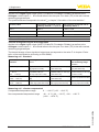
Electronics compartment
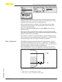
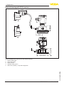
5.7 Double chamber housing with DIS-ADAPT
1
2
3
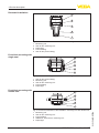
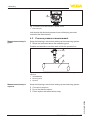
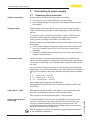
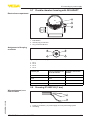
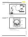
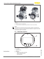
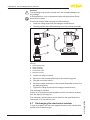
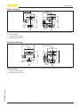
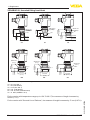
Fig. 29: View to the electronics compartment
1 DIS-ADAPT
2 Internal plug connection
3 Plug connector M12 x 1
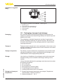
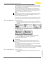
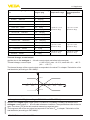
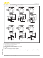
Assignment of the plug
connector
4
3
1
2
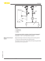
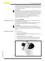
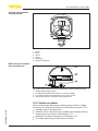
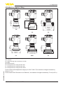
Fig. 30: Top view of the plug connector
1
2
3
4
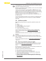
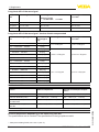
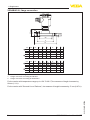
Wire assignment, connection cable
Pin 1
Pin 2
Pin 3
Pin 4
Contact pin
Colour connection cable in the sensor
Terminal, electronics
module
Pin 1
Brown
5
Pin 2
White
6
Pin 3
Blue
7
Pin 4
Black
8
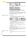
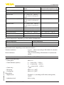
5.8 Housing IP 66/IP 68 (1 bar)
1
45028-EN-131010
2
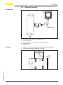
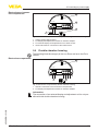
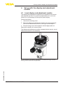
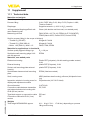
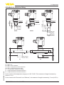
Fig. 31: Wire assignment fix-connected connection cable
1 brown (+) and blue (-) to power supply or to the processing system
2 Shielding
VEGABAR 82 • 4 … 20 mA/HART
29