1
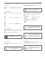
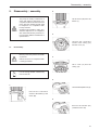
Disassembly / assembly
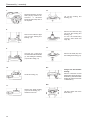
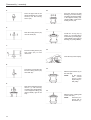
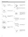
10.
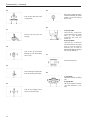
5.
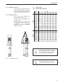
Press the deep groove ball
bearing (5) into the bearing
mounting (25)(design B/BF)
or the support housing (70)
(design M/MF) against the
locking sleeve (24).
Press the upper half of the
thrust ball bearing (6) (shaft
washer) into the locking
sleeve (24).
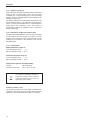
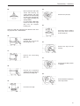
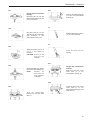
6.
11.
Push the locking sleeve (24)
onto the shaft (22).
Install the circlip (27) by
means of a mounting pliers
in the bearing mounting (25)
(design B/BF) or the support
housing (70) (design M/MF).
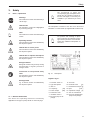
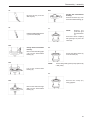
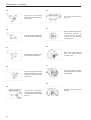
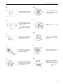
7.
12.
Bore the locking sleeve (24)
with shaft (22) to final
dimension.
Insert the key in the keyway.
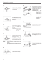
8.
Drive in the grooved pin (26)
into the locking sleeve (24)
and shaft (22).
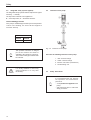
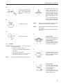
13.
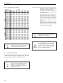
Shift the Spacer bush (2) on
the shaft (22).
NOTE:
In the design
with central
grease pump
replaced by a vbelt pulley.
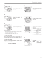
9.
Push-in the shaft (22) into the
lantern (1) with bearing
mounting (25) (design B/BF)
or the support housing (70)
(design M/MF) right to the
stop.
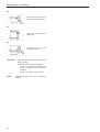
14.
Shift the lower coupling half
on the shaft (22).
NOTE:
44
Install the protection grid on
the lantern (1)!