1
Catalogue 2010
Preface
1
2
3
4
DEAR READER!
You will understand that we as manufacturers of air heating and ven-
INSTALLATION CONCEPTS
In addition to separate applications for heating and cooling, ventila-
tilation systems are proud of our product. Of course we love to see you suc-
ting and domestic hot water, Brink also supplies installation concepts. These
cessfully install our product. We have compiled this catalogue to a help you
complete solutions offer a healthy, durable and low energy living and wor-
as much as possible. The catalogue also lists the distributed products that
king climate so they fit in closely with present-day comfort requirements
were marketed under the brandname Innosource until the end of 2009. In
among end-users.
5
6
this booklet you will find all information you need - with your expertise
- to order the correct product or system. Here you will find the answer to
almost all your questions. If not, please contact our Sales Department or
QUALITY
7
The appliances and parts are of the highest quality, subject to con-
one of our consultants.
tinuous inspection throughout the production process, and they come
Our people will be happy to serve you.
with the CE mark. In addition, our appliances have a high efficiency. Brink
Climate Systems B.V. is certified under ISO 9001 and ISO 14001.
8
CLIMATE OK
In dwellings and non-residential buildings, the systems by Brink
Climate Systems B.V. contribute to a healthy, low-energy and comfortable
SUPPORT
Do you need support when making a design? Then call the people of
indoor climate. It will be obvious that our products satisfy the highest qua-
our Export Department. They will give you advice and come up with ideas
lity requirements. But we want more. That's why we are launching Climate
for an optimum solution for any installation.
9
OK. Climate OK is an initiative by Brink Climate Systems to arouse more
interest for the quality of the indoor climate among architects, developers,
Any questions? Please, do not hesitate to contact our Sales Department,
installers and end users.
phone +31 522 46 99 44.
FROM MANUFACTURING TO ASSEMBLY
Kind regards,
At Brink Climate Systems, member of the Centrotec Group, equipment
10
11
Brink Climate Systems B.V.
and parts are expertly and efficiently designed and produced in-house.
Ventilation units and air heaters by Brink Climate Systems are available in
many capacities and versions, including the necessary accessories.
All components are prefabricated and perfectly geared for each other,
making assembly effortless. You will find Brink Climate Systems applications
Johan van Renselaar, managing director
anywhere: in dwellings, bungalows, offices, health centres, sports centres,
schools, workshops, showrooms and production halls.
3
Table of contents
1
New products and concepts
1.1
1.2
1.3
1.4
1.5
2
3
4
9
New Sonair
Breathing Window
Renovent Excellent
Brink Sun Set
New Allure
9
10
11
12
13
Installation concepts
15
2.1
2.2
2.2.1
2.2.2
2.2.3
2.2.4
15
15
16
17
18
18
Introduction
Examples installation concepts
Ventilation and solar concepts for dwellings
Passive house concept
BQLS Concept
School ventilation concepts
Ventilation
19
3.1
3.2
3.2.1
3.2.2
3.2.3
3.2.4
3.3
3.3.1
3.3.2
3.4
3.4.1
3.4.2
3.5
3.5.1
3.5.2
3.5.3
19
20
20
30
41
47
50
50
53
58
58
62
66
66
68
80
Ventilation
Central ventilation
Renovent
Renovent accessories
Air Comfort Control (ACC) Dwelling ventilation
Flexivent
Distributed ventilation
Advance
Sonair stand-alone ventilation
School ventilation
Air Comfort Control (ACC) School ventilation
Renovent HR School ventilation
Miscellaneous ventilation
Dwelling ventilation box
Roof fans
Fan casing Allure
Air heating
4.1
4.2
4.2.1
4.2.2
4.2.3
4.2.4
4.2.5
4.3
4.3.1
4.3.2
4.3.3
Air heating
Indirect-fired appliances
BQLS, Brink quality of life system
Elan appliances general
Elan Duo
Elan heating/cooling
Elan
Direct-fired appliances
Allure
Brink HRE central heating appliance
Passive House
83
83
84
84
89
92
104
112
126
126
141
145
5
1
2
3
4
5
6
7
8
9
10
11
Table of contents
5
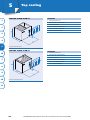
Top cooling
149
6
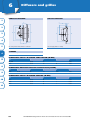
Diffusers and grilles
155
7
Air distribution systems
163
1
2
7.1
7.2
3
4
Brink Air Excellent System
Brink Air System
163
165
8
Thermostats and zone control
167
9
Filters
171
10 Service parts
10.1
10.1.1
10.1.2
10.1.3
10.2
10.2.1
10.2.2
10.2.3
10.3
10.3.1
10.3.2
10.3.3
10.3.4
10.3.5
10.3.6
10.3.7
10.3.8
10.3.9
10.3.10
10.3.11
10.3.12
5
6
7
8
9
10
11
11
General information
11.1
11.2
6
Service parts distributed ventilation
Renovent
ACC Dwelling ventilation
Flexivent
Service parts distributed ventilation
Advance
Sonair stand-alone ventilation
Dwelling ventilation box
Service parts air heater
BQLS, Brink quality of life system
Elan Duo
Elan heating/cooling
Elan
Allure
Furore
N appliance
Brink HRE central heating appliance
IN appliance
Flair
Capacitors
Fuses
General design information
General information, including general conditions of sale
and delivery
www.brinkclimatesystems.nl Phone +31 522 46 99 44 Fax +31 522 46 94 00
177
177
177
182
183
186
186
187
188
189
189
190
192
193
195
198
200
202
203
204
205
206
207
207
220
1
New products and concepts
1.1
1
1 New So
Sonair
GENERAL INFORMATION
1
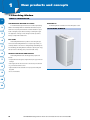
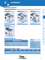
THE NEW SONAIR
The completely renewed Sonair is a wall ventilation appliance for
AVAILABILITY
The new Sonair is available as from the third quarter of 2010.
2
use in high-noise environments such as near airports, railways or busy
motorways. The air supply unit Sonair has a number of major innovations
SONAIR
such as the fan unit which is integrated in the wall sleeve. The installed
fan (with EC technology) guarantees a low energy consumption. Since the
3
fan remains outside the room, the system noise is limited and the design
indoor part is compact. Other important characteristics include the userfriendliness through the high-quality air filters and push buttons. With this
4
appliance Brink Climate Systems anticipates on the recently set ceilings for
maximum noise quantities that road and rail traffic may cause.
In addition to application in high-noise environments, of course the
5
new Sonair is also suitable for quickly and simply improving the ventilation
in other existing situations.
6
PRODUCT PROPERTIES AND BENEFITS
The new Sonair has the following product properties and benefits:
• The fan unit is integrated in the wall sleeve
7
• Low-energy EC fan
• High noise reduction through the exterior wall
SONAIR
• Possibility for (high-performance) air filtering
• Very simple installation
8
• Choice of front finishes
9
10
11
9
1
New products and concepts
1.2 Breathing Window
GENERAL INFORMATION
1
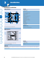
THE BREATHING WINDOW APPLIANCE
In 2010 Brink Climate Systems introduces the revolutionary Breathing
2
AVAILABILITY
The Breathing Window is available as from the third quarter of 2011.
Window. The Breathing Window is a distributed wall ventilation system
with heat recovery and optional demand-controlled ventilation. A special
BREATHING WINDOW
feature is the highly compact flat heat exchanger containing fine copper
3
wire. Application of this type of heat exchanger has made it possible to
develop a compact wall ventilation unit.
4
EPC GAINS
The Breathing Window makes it possible to achieve EPC gains up to
0.32. Because the Breathing Window does not require long air ducts, it is
5
excellently suitable for renovation of existing dwellings and buildings. Also
in new buildings, a Breathing Window contributes to improving the energy
label (for instance in dwellings, offices, hotels and health centres).
6
PRODUCT PROPERTIES AND BENEFITS
The Breathing Window has the following product properties and
benefits:
7
• Compact dimensions through use of high-efficiency fine copper wire heat
exchanger
• Fans integrated in the wall sleeve make for an extremely low sound level
8
• CO2 sensor-based automatic control
• Simple installation makes it suitable for new projects and existing buildings alike
9
• Choice of front finishes
10
11
10
www.brinkclimatesystems.nl Phone +31 522 46 99 44 Fax +31 522 46 94 00
1
New products and concepts
1.3 Renovent Excellent
GENERAL INFORMATION
1
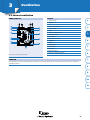
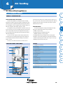
RENOVENT EXCELLENT
Brink Climate Systems developed further the familiar Renovent HR for
PARTS
The new appliance has many functionalities as standard. A bypass
balanced ventilation with heat recovery and equipped it with the latest
diffuser and an intelligent preheater are standard. The internal resistance
technology; the Renovent Excellent. The appliance has a capacity of 400
has been reduced to realise a low sound level and a low energy consump-
m3/h. The heat exchanger is broader for improved heat transfer and a lower
tion. The bypass is activated when the preconditions are met and it ensures
pressure drop.
that the indoor air is not unnecessarily heated under summary conditions.
2
3
If necessary, the preheater heats up the outdoor air to prevent the heat
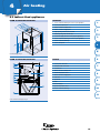
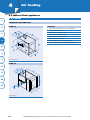
VERSIONS
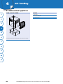
The Renovent Excellent is available in three versions:
A: Four air connections at the top (4b).
exchanger from freezing at low outdoor temperatures. It is activated when
the exchanger starts to freeze up. That guarantees optimum balanced
4
ventilation under all conditions.
B: Two connections at the top and two connections at the bottom (2b/2o).
C: Three connections at the top and one connection at the bottom (3b/1o).
The appliances are available in a right-handed or left-handed version.
AVAILABILITY
The new Renovent HR is available as from the second quarter of 2011.
5
COMPLETE NEW CONTROL SYSTEM
The ease of operation of this state-of-the-art control system has been
6
RENOVENT EXCELLENT
optimised. The electric rated power has been reduced by installing efficient
fans in combination with constant flow rate control. This control ensures
7
that the required flow rate is actually realised at changing duct pressures.
FILTERS
The appliance comes as standard with a G3 filter (F7 supply filter
8
optional). The filters are easily taken out. Of course this appliance also has
the familiar filter indication. On the basis of time or volume the indication
appears on the display, on the 3-way switch with LED indication and, if
9
installed, on the control panel for demand-controlled ventilation.
10
11
11
1
New products and concepts
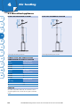
1.4 Brink Sun Set
GENERAL INFORMATION
1
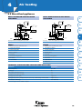
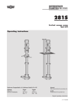
BRINK SUN SET
Every Brink Sun Set is composed of the following parts:
In cooperation with German sister company Wolf Heiztechnik Ger-
2
3
4
- Sealing plug set
Brink Sun Set. The Brink Sun Set comes in three standard sets, including
- Couplings pump group 4 x 22 mm
solar water heaters with capacities of 115, 200 and 300 litres. In addition
- Collector connectors (if necessary)
to these standard sets, Brink also offers made-to-measure solutions. Brink
- Pump group 10, with high head
offers a complete range of accessories so there is a fitting solution for any
- Expansion vessel
situation. The three standard versions are suitable for single households up
- Connecting kit
to households of four tot six.
- Flexible connecting kit
- Solar water heater
PARTS
5
6
- Solar thermal collector Top Son F3-1
many, B developed a completely new line of solar water heater systems, the
- Manual bleeder
Every Brink Sun Set features unique solar thermal collectors that are
- ANRO fluid, KIWA approved
excellently suitable for the European climate. The use of special glass
- Controller, SM1
guarantees a high efficiency, also in the European climate.
- Mixing valve
BRINK SUN SET
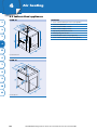
VERSIONS
As stated above, the Brink Sun Set comes in three standard versions.
A: Sun Set CV 1-115, with one solar thermal collector and one
7
115-litre solar water heater.
B: Sun Set CV 2-200, with one solar thermal collector and one
200-litre solar water heater.
C: Sun Set CV 3-300, with three solar thermal collectors and one
8
300-litre water heater.
9
10
11
Basic diagram Brink Sun Set central heating 1-115
12
www.brinkclimatesystems.nl Phone +31 522 46 99 44 Fax +31 522 46 94 00
1
New products and concepts
1.5 New Allure
GENERAL INFORMATION
1
THE NEW ALLURE
Brink Climate Systems developed the familiar Allure series further.
Three new appliances have been added to the range. The appliance B-16
VERSIONS
The new Allure is available in six versions in Upflow as well as Down-
2
flow.
3
HR is available with three different air flow rates and a
A: B-16 HR with 1350 m /h
B-25 HR with two different air flow rates. That way the appliance can be
B: B-16 HR with 2100 m3/h
tuned even better to the installation, more air for cooling capacity, without
C: B-16 HR with 3400 m3/h
a too great heating capacity.
D: B-25 HR with 2100 m3/h
The new Allure has a new burner controller. The controller complies
with the latest requirements and uses less energy. This has been combined
3
E: B-25 HR with 3400 m3/h
F: B-40 HR with 3400 m3/h
4
with a new operating system with a graphic display for improved tuning
and reading out of the appliance. In addition, a new room thermostat has
been developed. This beautifully designed clock thermostat with display is
easily operated, with a time program (clock function) as well as by manual
NEW CONTROL SYSTEM
The new control system and the operation of the new Allure are fully
in line with the state-of-the-art and ease of operation.
5
control.
AVAILABILITY
6
The new Allure is available as from the second quarter of 2010.
7
8
9
10
11
13
2
Installation concepts
2.1 Introduction
GENERAL INFORMATION
1
EPC REDUCTION
We are happy to consult with the client on the energetic and comfort
It requires ever more installation engineering measures to further
requirements made upon the dwelling(s). When the wishes have been de-
reduce the energy consumption in dwellings. The intention is to reduce the
fined, Brink Climate Systems can take care of the right system choice, with
EPC for newly built dwellings even further in 2011, with the eventual target
or without the required technical specifications and starting points for the
of developing energy-neutral dwellings in 2020.
building-physical characteristics of the dwelling(s).
TOTAL SOLUTION
CLIMATE OK
2
3
The measures that must be implemented cannot be realised by just
In addition to energy efficiency, realising sufficient quality is another
one product. That increasingly becomes a joint effort between building
requirement. With ‘Climate Ok’ by Brink Climate Systems we can map out
physics and total installation engineering solutions.
the quality aspects considered important by the residents and make them a
4
subject of discussion, but more importantly, we can guarantee them.
BRINK CLIMATE SYSTEMS ELIMINATES YOUR
5
WORRIES
Brink Climate Systems is your partner of choice with regard to installation solutions. For new projects, but expressly also for existing buildings,
6
Brink Climate Systems developed installation concepts to actually realise the
various savings targets. Is the focus on CO2-emission, or is it all about the
energy costs for the end user? We have the right solution. Our consultants
7
can provide advice during the development process.
2.2 Examples installation concepts
8
GENERAL INFORMATION
9
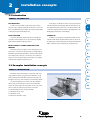
Brink Climate Systems offers installation concepts in the field of solar
energy, ventilation, heating, cooling and hot water. Installation concepts
require customised advice. Brink Climate Systems makes it possible to go
10
through the entire process, from calculation up to and including realisation.
The following examples give you an idea of the options that Brink
Climate Systems can offer with respect to the various total installation
11
solutions. The various examples are only indicative. Of course other combinations of systems are possible. Every system has its own solution.
2.2.1: Brink Ventilation and solar concepts for dwellings
2.2.2: Brink Passive House concept
2.2.3: Brink BQLS concept
2.2.4: Brink School Ventilation concepts
15
2
Installation concepts
2.2 Examples installation concepts
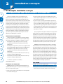
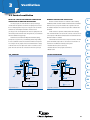
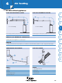
2.2.1 VENTILATION AND SOLAR CONCEPT FOR DWELLINGS
1
In many cases, installation concepts are not standard. For every
2
situation it is assessed what the most favourable energetic solution is.
demand is higher, through application of a collector area of some 4.6 m2
But it is not only about the energetically most favourable solution. The
and a 200 litre solar water heater.
balance between investment costs, EPC reduction and a good mutual match
3
4
2. The Sun Set CV 2-200 is a perfect choice for dwellings were the water
3. The Sun Set CV 3-300 is commonly used in dwellings occupied by more
between the separate products is another consideration. Yet in for instance
than four or were the water demand is very high. The 300 litre solar wa-
renovation projects is often possible to use a standard solution despite
ter heater in combination with the solar thermal collectors ensures a very
the diversity of the individual dwellings. To facilitate that, for instance in
high yield. Both the energy savings and the reduction of CO2-emissions
the field of solar systems Brink Climate Systems developed three different
are guaranteed with these carefully composed sets. Savings in gas for hot
standard systems, known as Brink Sun Set. In combination with the various
domestic water may increase to as much as 60%. This standard set has a
ventilation solutions offered by Brink Climate Systems, great steps can be
major influence on the EPC.
made in various disciplines. In new projects, municipalities and housing
5
corporations set great store by the EPC value, but they also have other
ambitions, such as with regard to CO2- emission.
By way of supplement with regard to ventilation in new projects, Brink
Climate Systems can also supply customised ventilation systems. The Renovent HR heat recovery unit ensures a continuous supply of fresh air in the
CERTIFICATE OF EQUIVALENCE
6
7
dwelling and it comes in three versions. Four connections at the top, two
Certificates of equivalence are available for all solar and ventilation
connections at the top and two at the bottom, and three connection at the
concepts. This certificate is awarded after a test by an independent body.
top and one at the bottom. Every situation requires its own appliance. The
The tests were carried out at a consumption of 110 l/day, 15 °C => 60°C:
major EPC savings from application of the Renovent HR and the combina-
•
tion with a Brink Sun Set make it possible to realise very low EPC values.
Determining the energetic efficiency of the heat recovery appliance ‘Brink Renovent HR 4/0 R Small’ Measuring Certificate under
NEN 5138:2004
8
•
•
9
10
Example B: The Breathing Window and the Advance. The Breathing
Determining the energetic efficiency of the heat recovery appliance ‘Brink
Window and the Advance are excellently suitable to ventilate one habita-
Renovent HR 4/0 R Medium’ Measuring Certificate under NEN 5138:2004
ble room. Both products are also the perfect choice as the heart of a com-
Determining the energetic efficiency of the heat recovery appli-
plete dwelling ventilation system. Application of the Breathing Window or
ance ‘Brink Renovent HR 4/0 R Large’ Measuring Certificate under
the Advance for instance in the living room (where heat recovery is often
NEN 5138:2004
desired for reasons of comfort) combined with for instance mechanical ex-
•
Annual efficiency solar water heater Brink Sun Set CV 2-200 with cap-
haustion in the wet rooms and air supply with grilles in the other habitable
ped top heat exchanger for NEN 5128:2004
rooms (bedrooms) results in an excellent ratio between EPC reduction and
•
Annual efficiency solar water heater Brink Sun Set CV 3-300 with cap-
investment. The EPC can be reduced even further through the use of solar
ped top heat exchanger for NEN 5128:2004
water heater system by Brink Climate Systems. As a starting point, the Sun
Set CV 2-200 has been selected for the following example. This combination
11
The certificates of equivalence are available at
is excellently suitable for a dwelling occupied by four.
www.brinkclimatesystems.nl
EPC GAINS
EXAMPLES: EPC REDUCTION
Example A: Sunset CV 3-300 with Renovent HR. Every Brink Sun Set
supplied by Brink Climate Systems is a complete solar water heater system.
The series is composed of three systems:
Example A: Sun Set CV 3-300 and Renovent HR
0.04*
Example B: Sun Set CV 2-200, Breathing Window and Advance
0.4
* With CO2-sensor control, the EPC value can be reduced by another 0.030.08. These values are based on the Novem reference terraced house.
1. The Sun Set CV 1-115 with its compact dimensions is excellently suitable
for renovation and new projects.
16
www.brinkclimatesystems.nl Phone +31 522 46 99 44 Fax +31 522 46 94 00
2
Installation concepts
2.2 Examples installation concepts
EXAMPLES FROM D-LABEL TO A-/B-LABEL
Example A: Brink ACC system. Since the Brink ACC system is easily
may be the highly compact Sun Set CV 1-115, with a collector area of 2.3 m2
1
and a 115-litre solar water heater.
retrofitted, the ACC system is one of Brink's ventilation solutions for improving the energy label. Major energy savings are realised by the ventilation
system with demand-control per room.
ADVICE AND MORE INFORMATION
The above examples provide an indication of the savings to allow more
2
insight into the possibilities of the Brink ventilation and solar system conExample B: Brink Sun Set. If further improvement of the energy label is
cepts. Of course there are more solutions. The consultants of Brink Climate
desired or the client or occupant wants a sustainable installation solution,
Systems will be happy to give you advice. You will find more information
Brink Climate Systems can offer a customised system with the Sun Set. In
on the ventilation systems in Chapter 3 and on the Brink Sun Set in Chapter
view of the often limited room in existing social housing, a good choice
4 of this catalogue.
3
4
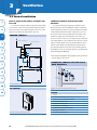
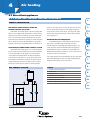
2.2.2 PASSIVE HOUSE CONCEPT
THE PASSIVE HOUSE APPLIANCE
The Passive House Appliance by Brink Climate Systems is an integra-
appliance. The vessel has a capacity of 200 litres of sanitary water for maxi-
5
mum utilisation of solar energy to guarantee perfect hot water comfort.
ted appliance in which various disciplines such as heating, ventilating and
Primary heating of the vessel is through the solar thermal collectors and, if
heating domestic hot water have been combined in one compact appliance.
necessary, a high-efficiency Brink HRE central heating boiler heats it further.
6
The unique control system and the fact that all components are mounted
together in one housing, reduce the risk of installation errors and guarantee maximum result. The Passive House Appliance is a giant leap forwards
towards energy-neutral dwellings.
APPLICATION
7
The Passive House concept is suitable for newly built dwellings that
comply with the Passive House criteria so they are almost energy-neutral,
referred to as Passive Houses. In addition, the concept is also suitable for
The Passive House concept is characterised by a compact solution,
innovative renovation projects. So far passive homes are mainly being built
integrating domestic hot water, ventilation and heating. As a result of the
in German-speaking countries, Scandinavia and Belgium. The Passive House
sophisticated dwelling design, heat can hardly escape from the Passive
Appliance offers an affordable solution for ensuring comfortable living and
House. That is because the design features excellent envelope insulation,
air quality, certainly at increasing energy costs.
9
without thermal bridges and with adequately sealed joints and cracks,
combined with carefully thought out sun orientation and sun screening.
8
ADVICE AND MORE INFORMATION
Consequently, it requires hardly or no energy to keep the dwelling at the
It is highly important for passive construction that the installation
right temperature in winter and the dwelling remains pleasantly cool in
design is taken into account in the early stages of the development of the
summer.
dwelling. Our consultants like to be involved in the development of passive
10
houses from the initial stage. Experience has taught us that timely planning
SOLAR WATER HEATER
Brink Climate Systems developed two Passive House Appliances. Both
11
of installations in these dwellings has a major influence on the correct
performance of the installation and will prevent delays in the construction
versions of the Passive House Appliance use a solar thermal collector to
process. The consultants of Brink Climate Systems are happy to participate
generate heat and to store it in a solar water heater. That is the heart of the
in this respect. You will find more information on the Passive House Ap-
system. The solar water heater supplies heat and domestic hot water. The
pliance in Chapter 5 of this catalogue.
way in which heat is generated and the capacity depend on the choice of
17
2
Installation concepts
2.2 Examples installation concepts
2.2.3 BQLS CONCEPT
1
BQLS, BRINK QUALITY OF LIFE SYSTEM
BQLS, the Brink Quality of Life System, is a modular concept for
2
3
highly comfortable and energy-friendly heating, cooling and ventilating
WIDELY APPLICABLE IN NEW PROJECTS AND
RENOVATION
Its modular design makes BQLS suitable for almost all types of dwel-
of dwellings. BQLS is built around the series Elan Duo 2-zone air heaters.
lings and comfort levels: from mass production to (very) luxurious dwellings
As standard, it has two independently operating zones for heating or coo-
and for new projects as well as renovation and renewal projects. From basic
ling. One for the living zone and one for the sleeping zone. The Renovent
to all-in comfort systems and everything in between. Extra functionalities
HR heat recovery unit recovers the heat from the ventilation air and the
and comfort can also be added when replacing an existing installation.
heat source is a Brink 36/30 HRE central heating appliance with integrated
4
5
DHW supply class CW-5. The complete installation is connected to a central
control panel, the Climate Master. The Climate Master automatically con-
ADVICE AND MORE INFORMATION
The broad range of solutions makes BQLS suitable for any dwelling.
trols all necessary functions for heating, cooling and ventilating. The basic
The interaction between supply and demand is the key to success. When
installation can be extended as desired with many options such as cooling
the wishes have been defined, Brink Climate Systems can arrange the right
and heating with a heat pump. Of course the BQLS system can also be
choices and installations. Our consultants will be happy to participate. You
complemented with the Brink Sun Set.
will find more information on BQLS in Chapter 5 of this catalogue.
6
2.2.4 SCHOOL VENTILATION CONCEPTS
7
BROAD RANGE SCHOOL VENTILATION
Improving the indoor climate in schools is a topical subject. Surveys
8
9
RENOVENT HR SCHOOL VENTILATION
The Renovent HR has been extended with a special supply duct for a
have shown that in more than 80% of current schools and daycare centres
very even air distribution in the classroom and a constructional cupboard
the indoor climate is seriously inadequate. Brink Climate Systems has deve-
for situations where it is not possible to place the Renovent HR in a nearby
loped a wide range of solutions with or without heat recovery for schools.
room, for instance a storage room. Automatic control with CO2-sensors and
automatically increased night ventilation to cool the classroom with cool
ACC SCHOOL VENTILATION
outdoor air are some of the special features.
The Brink ACC system is an extremely effective way for ventilating
10
classrooms. Demand-controlled ventilation (clock- or CO2-controlled),
distributed or central extraction, and the possibility to combine the system
with any existing ventilation systems are just a few of the special system
characteristics.
11
18
www.brinkclimatesystems.nl Phone +31 522 46 99 44 Fax +31 522 46 94 00
3
Ventilation
3.1 Ventilation
GENERAL INFORMATION
1
Brink Climate Systems is a total supplier in the field of integrated
The ventilation systems by Brink Climate Systems are also available
solutions for heating, ventilation and hot water. With regard to ventilation
without heat recovery. These too ensure constant and controlled supply of
there are many possibilities to make dwellings and buildings healthier,
fresh, filtered outdoor air.
2
more energy-efficient and more comfortable. Brink Climate Systems offers
an extensive product range. These ventilation solutions not only perform
effectively, but they are also easy to install. In addition, our products are
suitable for new projects and existing buildings alike.
NEW IN THE RANGE
In 2010 Brink Climate Systems introduces the Breathing Window (distri-
3
buted ventilation). Learn more about the Breathing Window in Chapter 1
New products and concepts.
Brink Climate Systems supplies central, distributed and school ventilation systems. Central ventilation systems cater for the ventilation need in
BENEFITS OF VENTILATION SOLUTIONS BY BRINK
various habitable rooms from a central point. Central ventilation products
CLIMATE SYSTEMS
include Renovent HR, ACC Dwelling ventilation and Flexivent.
• Make a major contribution to energy savings.
Distributed ventilation systems can do without long ventilation ducts
5
• Guarantee a healthy and comfortable indoor climate.
and they are installed separately in every room to realise the desired indoor
• Offer the highest EPC gains at the lowest costs.
climate. Distributed ventilation products include Advance and Sonair stand-
• It is the ultimate solution to comply with the standard (EPC and Building
alone. The Brink school ventilation systems are designed for improving the
6
Decree).
interior air quality, particularly in classrooms. The system are easily retrofit-
• Simple control.
ted and they fully automatically control the ventilation rate. Brink Climate
• Low-maintenance.
Systems offers Renovent HR en ACC School ventilation. ‘Miscellaneous ven-
• Fresh air 24 hours a day.
tilation’ includes the dwelling ventilation box, roof fans and the fan casing.
• Very low noise level.
The ventilation systems by Brink Climate Systems are available with
Products
with heat recovery results in continuous and controlled ventilation. Every
moment of the day the desired indoor climate is realised at the lowest pos-
Central
Renovent HR
With heat
Without heat
recovery
recovery
the warm exhaust air to the clean, fresh outdoor air. That way 95% of the
Distributed
9
•
Flexivent
•
Advance
•
Breathing Window
•
Sonair stand-alone
8
•
Ait Comfort Control
sible energy consumption. The heat recovery system transfers the heat of
heat is preserved and waste of energy is prevented.
7
VENTILATION PRODUCTS
balanced ventilation with heat recovery. Installation of balanced ventilation
4
10
•
Dwelling ventilation
box
•
Roof fans
•
Fan casing
•
11
19
3
Ventilation
3.2 Central ventilation
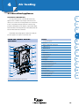
3.2.1 RENOVENT
1
GENERAL INFORMATION
2
THE RENOVENT HR APPLIANCE
Renovent HR Large, Medium and Small have specifically been designed
3
The electric and control system connections are placed on the outside.
The appliances come with a display for setting and reading out functions.
for balanced ventilation with heat recovery. The thermal energy in the foul
That enables continuous adjustment of the volume without having to open
air that is discharged from the dwelling is used to heat the fresh, clean out-
the appliance.
door air that is brought in. The heat exchanger transfers 95% of the heat,
so it is no longer necessary to heat the ventilation air.
4
5
6
The heat recovery units are made of a sheet steel, cream epoxy-coated
Renovent HR Medium and Large are both available in three versions.
A: Four air connections at the top (4b).
body (RAL 1013) containing a PETG heat exchanger and two 'constant flow'
B: Two connections at the top and two connections at the bottom (2b/2o).
fans. In addition, the appliances are suitable for three adjustable flow rates.
C: Three connections at the top and one connection at the bottom (3b/1o).
The interior is made of high-quality CFC-free synthetic. This synthetic
material has a high thermal resistance, is flame-extinguishing and non-
Renovent HR Small is available in the version with four air connections
hygroscopic. The appliances come with two standard filters (supply filter
at the top (4b). If required, the appliance can be mounted in a kitchen
G3, exhaust filter G3). The filters can easily be taken out through the dark-
cupboard.
blue filter door. These filters remove 95% of the dust from the air.
The accessories for the Renovent HR are listed in the chapter ‘Renovent
The air connections of all versions come with a groove for sealing
rings. The appliances are available in a right-handed or left-handed version.
HR, accessories’.
7
RENOVENT HR LARGE, MEDIUM AND SMALL
The control unit of the Renovent HR Large, Medium and Small controls
8
and monitors the safe operation of the appliance and ensures that the air
quantities remain constant and at the preset values.
9
10
11
20
www.brinkclimatesystems.nl Phone +31 522 46 99 44 Fax +31 522 46 94 00
3
Ventilation
3.2 Central ventilation
TECHNICAL INFORMATION
1
RENOVENT HR
RENOVENT HR
RENOVENT HR
2
3
4
Large and Medium 4b R
Large and Medium 3b/1o R
5
Large and Medium 2b/2o R
RENOVENT HR
6
7
8
9
Small 4b R
10
RENOVENT HR SMALL, MEDIUM EN LARGE
SLEEVES
Connection
right
Links
1 To dwelling
To dwelling
1
3
2 To atmosphere
To atmosphere
2
4
3 From dwelling
From dwelling
3
1
4 From atmosphere
From atmosphere
4
2
5 Electric connections
11
6 Condensate discharge
Display at the front
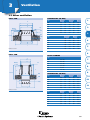
DIMENSIONS RENOVENT HR (IN MM]
Type
A
B
C
D
E
F
G
H
I
J
K
L
M
n
Large
336
126
165
675
89
114
53
602
220
385
430
455
-
-
Medium
321
121
165
675
89
99
45
602
210
385
420
445
-
-
Small
213
77
79
560
75
125
45
600
145
248
290
315
168
-
21
3
Ventilation
3.2 Central ventilation
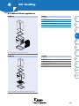
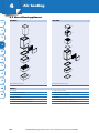
RENOVENT HR
PARTS
1
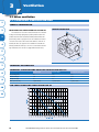
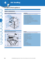
A Exhaust air flow
B Supply air flow
1 Indoor temperature sensor
2
2 Heat exchanger
3 Filters
4 Outdoor temperature sensor
3
5 Communication port
6 Metric swivel
7 OpenTherm connection
4
8 Option pcb (non-standard)
9 Supply fan
10 Basic pcb
5
11 Computer port
12 Control Panel
13 Exhaust fan
6
14 Connection orifices
Front view Renovent HR Large and Medium 2b/2o R
7
15 Connection condensate discharge
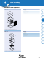
RENOVENT HR
8
9
10
PARTS
11
1 Bypass diffuser
Front view cross-section bypass unit for night ventilation
2 Diffuser control
for Renovent HR Large and Medium
3 Filters
REMARK
Renovent HR can be reversed. For that purpose the front and rear covers are interchanged. The air connections remain the same. This is described in the
installation instructions.
22
www.brinkclimatesystems.nl Phone +31 522 46 99 44 Fax +31 522 46 94 00
3
Ventilation
3.2 Central ventilation
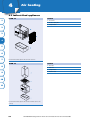
RENOVENT HR
PARTS
1
A Exhaust air flow
B Supply air flow
1 Indoor temperature sensor
2
2 Heat exchanger
3 Filters
4 Outdoor temperature sensor
3
5 Communication port
6 Metric swivel
7 OpenTherm connection
4
9 Supply fan
10 Basic pcb
11 Computer port
5
12 Control Panel
13 Exhaust fan
14 Connection orifices
6
15 Connection condensate discharge
Front view cross-section Renovent HR Small
REMARK
7
Renovent HR can be reversed. For that purpose the front and rear covers are interchanged. The air connections remain the same. This is described in the
installation instructions.
8
9
10
11
23
3
Ventilation
3.2 Central ventilation
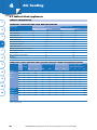
TECHNICAL SPECIFICATIONS RENOVENT HR LARGE
1
BYPASS UNIT)
Technical data
2
3
4
5
(BOTH FOR APPLIANCE WITH AND WITHOUT
Renovent HR Large
Dimension duct connection [mm]
Ø 160 and Ø 180
Weight [kg]
32 (exclusive of weight bypass unit of 3.5)
Supply voltage [V~/Hz]
230/50
Protection degree
IP31
Temperature efficiency [%]
95
Mode
Absence mode
Presence mode
Cooking/showering mode Maximum mode
Ventilation capacity [m3/h]
100
200
300
400
Resistance ducts system [Pa]
10
40
83
150
Rated power [W]
20
56
136
304
EPS calculation
Brink Climate Systems has information available for correctly entering data in an EPS calculation. Please contact our Consultancy Department.
6
7
8
SOUND CAPACITY LEVEL L W RENOVENT HR LARGE
Acoustic data
Absence mode
Presence mode
Cooking/showering mode
Static pressure [Pa]
40
80
240
Acoustic capacity housing emission [dB(A)]
<32
42
53
Acoustic capacity duct “from" dwelling [dB(A)]
<31
38
47
Acoustic capacity duct “to" dwelling [dB(A)]
51.5
62
69
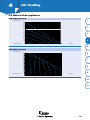
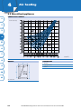
FAN GRAPH RENOVENT HR LARGE
Resistance ducts system [Pa]
9
10
SRZHUSHUIDQ:
11
Flow rate [m 3/h]
24
www.brinkclimatesystems.nl Phone +31 522 46 99 44 Fax +31 522 46 94 00
3
Ventilation
3.2 Central ventilation
TECHNICAL SPECIFICATIONS RENOVENT HR MEDIUM
(BOTH FOR APPLIANCE WITH AND
1
WITHOUT BYPASS UNIT)
Technical data
Renovent HR Medium
Dimension duct connection [mm]
Ø 150 and Ø 60
Weight [kg]
31 (exclusive of weight bypass unit of 3.5)
Supply voltage [V~/Hz]
230/50
Protection degree
IP31
Temperature efficiency [%]
95
2
3
Mode
Absence mode
Presence mode
Cooking/showering mode Maximum mode
Ventilation capacity [m3/h]
100
150
225
300
Resistance ducts system [Pa]
18
45
100
170
Rated power [W]
19
36
86
180
4
3
5
EPS calculation
Brink Climate Systems has information available for correctly entering data in an EPS calculation. Please contact our Consultancy Department.
6
SOUND CAPACITY LEVEL L W RENOVENT HR MEDIUM
Acoustic data
Absence mode
Presence mode
Cooking/showering mode
Static pressure [Pa]
40
80
160
Acoustic capacity housing emission [dB(A)]
29
38
47
Acoustic capacity duct “from" dwelling [dB(A)]
<24
33
41
Acoustic capacity duct “to" dwelling [dB(A)]
49
56
66
7
8
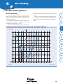
FAN GRAPH RENOVENT HR MEDIUM
Resistance ducts system [Pa]
9
10
SRZHUSHUIDQ:
11
Flow rate [m 3/h]
25
3
Ventilation
3.2 Central ventilation
TECHNICAL SPECIFICATIONS RENOVENT HR SMALL
1
2
3
Technical data
Renovent HR Small
Dimension duct connection [mm]
Ø 125
Weight [kg]
25
Supply voltage [V~/Hz]
230/50
Protection degree
IP31
Temperature efficiency [%]
95
Mode
Absence mode
3
4
Presence mode
Cooking/showering mode Maximum mode
Ventilation capacity [m /h]
75
100
150
180
Resistance ducts system [Pa]
24
42
102
150
Rated power [W]
25
34
74
116
EPS calculation
5
Brink Climate Systems has information available for correctly entering data in an EPS calculation. Please contact our Consultancy Department.
6
Acoustic data
SOUND CAPACITY LEVEL L W RENOVENT HR SMALL
7
8
Absence mode
Presence mode
Cooking/showering mode
Static pressure [Pa]
40
80
160
Acoustic capacity housing emission [dB(A)]
32
39
48
Acoustic capacity duct “from" dwelling [dB(A)]
31
37
46
Acoustic capacity duct “to" dwelling [dB(A)]
49
56
66
FAN GRAPH RENOVENT HR SMALL
Resistance ducts system [Pa]
9
10
SRZHUSHUIDQ:
11
Flow rate [m 3/h]
26
www.brinkclimatesystems.nl Phone +31 522 46 99 44 Fax +31 522 46 94 00
3
Ventilation
3.2 Central ventilation
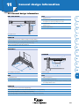
TECHNICAL INFORMATION RENOVENT HR APPLIANCES
1
EXTENSION WITH BYPASS UNIT FOR NIGHT
VENTILATION
Renovent HR large and Medium are available with a bypass for night
ventilation that shuts off almost completely. In summer this bypass unit
The wiring of this low-voltage rpm control must be installed separate
from the 230 V mains supply! Renovent HR Large, Medium and Small come
as standard with a power cable with plug. Renovent HR Large, Medium and
2
Small can optionally be fitted with a Perilex plug.
ensures that cool night air replaces in so far as possible the indoor air that
Refer to ISSO 61 and 62 for correct installation of ventilation systems
has been heated during the day. The air is routed through the bypass unit.
with heat recovery. These describe how a properly performing ventilation
The appliance comes with an automatic control system that opens and
system with heat recovery can be created.
3
closes the bypass valve.
A bypass unit can also be retrofitted by the installer or the user. This
bypass unit leads roughly 70% of the supply air around the Renovent HR
heat exchanger.
A suitable bypass unit that can be retrofitted is also available for the
RENOVENT HR LARGE, MEDIUM AND SMALL
Renovent HR Large, Medium and Small can be mounted on the floor
4
or on the wall. A mounting support for floor mounting is available.
Impact sound must be avoided. All versions of the Renovent HR Large,
Renovent HR 250 with ‘constant flow’ fans and the Renovent HR 325. These
Medium and Small come with a separate mounting set. It allows vibration-
appliances have been supplied until September 2004.
free mounting to the wall. This should preferably be done to a solid wall
5
with a mass of 200 kg/m2.
6
EXTENSION WITH OPTION PCB
Renovent HR Large and Medium can be fitted with an option pcb. It
can be used to control various accessories, for instance an electric preheater
and/or postheater (1000 W), a diffuser for sending extra ventilation air to
INSTALLATION BYPASS UNIT FOR NIGHT
VENTILATION
7
The bypass unit for night ventilation is mounted to the front of the
certain rooms or an emergency contact. In addition, the option pcb has
Renovent HR Large or Medium with the aid of the supplied screws. Then
an input for a CO2-sensor and a moisture sensor. The appliances can be
the standard front cover of the appliance for the bypass unit can be
supplied with premounted option pcb. The option pcb is also available as
mounted. The bypass unit comes with two filters which are longer than the
service kit for retrofitting.
standard filters for the Renovent HR Large and Medium. That is because the
8
appliance is 80 mm deeper after installation of the bypass unit. Installation
INSTALLATION GENERAL
It is important to place the appliance level and to choose an instal-
of the bypass unit is also possible for the version of the Renovent HR Large
and Medium.
9
lation room that is frost-free and allows installation of an adequate
condensate discharge with air trap. In addition, the condensate discharge
10
must be installed at a pitch.
At the front of the appliance there must be a free space of at least 700
mm for filter cleaning and appliance maintenance (780 mm for appliances
11
with a bypass unit).
For the low voltage rpm control, the installer must install a 4-core data
cable from the appliance to the 3-way switch. When using a 3-way switch
with filter indication, a 6-core modular data cable is required.
27
3
Ventilation
3.2 Central ventilation
3.2.2 RENOVENT ACCESSORIES
1
GENERAL INFORMATION
GENERAL
A properly performing heat recovery installation starts with a good
design, use of the right products and expert assembly. For the key starting
REMOTE CONTROL: 3-WAY SWITCH (WITH FILTER
INDICATION)
The 3-way switch allows the user to choose between three modes:
points for a proper design, we refer to the chapter ‘General design infor-
1. absence mode, 2. presence mode and 3. cooking/showering mode. The
mation’.
switch is quickly and easily connected on the outside of the appliance using
The Renovent HR forms the heart of a heat recovery installation. You
will find more information on this appliance in the chapter ‘Renovent
HR, appliances’. Information on ducts and diffusers can be found in the
chapters with those same names later in this catalogue. This chapter will
2
3
a data cable and a connector. With the aid of a splitter you can easily connect several switches, for instance an additional switch in the bathroom.
4
The 3-way switch has a filter indication light. That shows when the
filter has to be cleaned. Very convenient for the resident.
provide you with all information on the accessories necessary to create a
5
good installation.
6
7
8
9
10
11
29
3
Ventilation
3.2 Central ventilation
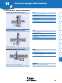
REMOTE CONTROL: WIRELESS
1
The switch on the transmitter allows the user to choose between absence
In addition to the 3-way switch (with filter indication) a wireless
remote control is available. The radiographically operated wireless remote
control consists of a transmitter unit (RF transmitter) and a receiver (RF
2
mode, presence mode, cooking/showering mode or the clock setting (time
function).
A kit containing a transmitter and a receiver is available for simply re-
receiver). Several transmitters can be set for one appliance, for instance in
trofitting a second switch in the bathroom. This kit can be used for the Small,
the kitchen as well as in the bathroom. Additional transmitters can easily
Medium, Large and SWB.
be signed on to the receiver.
3
RENOVENT HR LARGE, MEDIUM AND SMALL
4
:$<6:,7&+:,7+
),/7(5,1',&$7,21
5
$EVHQFHPRGH
32:(53/8*
9+]
3UHVHQFHPRGH
6
&RRNLQJ6KRZHUPRGH
7
8
9
3-way switch with filter indication
RENOVENT HR LARGE, MEDIUM, SMALL
RENOVENT HR LARGE, MEDIUM, SMALL
Transmitter with 2 settings
Transmitter with 4 settings
10
11
30
www.brinkclimatesystems.nl Phone +31 522 46 99 44 Fax +31 522 46 94 00
3
Ventilation
3.2 Central ventilation
BRINK CO2-SENSOR FOR DEMAND-CONTROLLED
VENTILATION IN ONE HABITABLE ROOM.
Over the past years, the carbon dioxide level (CO2) is increasingly
DEMAND-CONTROLLED VENTILATION
1
Demand-controlled ventilation is an installation solution enabling
distributed, demand-controlled ventilation within the balanced ventilation
considered the main parameter for the indoor air quality. The CO2 level in
with heat recovery concept. The ventilation rate is geared to the need.
the room mainly depends on the presence of people in the room and the
The available ventilation air is routed to the place where ventilation air is
ventilation rate. Controlling the ventilation on the basis of CO2
demanded.
percentage on the one hand guarantees the indoor air quality and on the
A TNO certificate of equivalence indicates that the EPC advantage
other hand it prevents ventilation at the wrong moment, excess ventilation.
from controlled demand is 0.072 (2-zone time control) to 0.081 (2-zone CO2-
That means additional energy savings.
control system). A TNO-authorised ‘Recalculation form demand-controlled
The Brink CO2-sensor with its Non-Dispersive Infra-Red measuring
principle has a long service life, is self-calibrating and has a high stability.
2
3
balanced ventilation’ is available.
Communication between the various components is wireless. The CBB
It comes as standard in a surface-mounted version with both a relay and a
(Control Panel Brink) components are connected to be 230 V mains in an
0-10 V output. The relay output can be used to switch between 2 settings
electrical box. The CBB has the following control options:
on the Renovent. The 0-10V output can be used for a continuous control
• Automatic based on presence (CO2-sensor)
system. Then the sensor must be connected to the Renovent option pcb.
• Automatic based on a time program (clock function)
4
5
• Manual control
6
CO 2 -SENSOR
CLOCK FUNCTION
&RQQHFWLRQFDEOH
KHDWUHFRYHU\:7:
&RQWUROER[
&RQQHFWLRQ
FDEOHGLIIXVHU
&RQQHFWLRQFDEOH
KHDWUHFRYHU\:7:
7
&RQWUROER[
&RQQHFWLRQ
FDEOHGLIIXVHU
&RQQHFWLRQ
FDEOHGLIIXVHU
&RQQHFWLRQ
FDEOHGLIIXVHU
6OHHSLQJ
]RQH
8
6OHHSLQJ
]RQH
9
&26HQVRU
'LIIXVHU
'LIIXVHU
$FRXVWLFKRVH
$FRXVWLFKRVH
10
/LYLQJ]RQH
/LYLQJ]RQH
&ORFN &%%
&26HQVRU
Setup with CO 2-sensor
11
Setup with clock function
31
3
Ventilation
3.2 Central ventilation
1
EASE OF VENTILATION, ENERGY ECONOMY AND
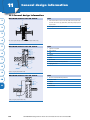
CONNECTOR CENTRAL HEATING WITH HEAT
EPS GAIN
RECOVERY
If an air heater is installed in combination with a Renovent HR, adding
2
In cooperation with Intergas Verwarming, an installation solution
a CO2-sensor in the return air flow enables demand-controlled ventilation.
has been developed for Renovent HR Medium en Small for combining the
Moreover, this feature creates additional EPS gains of about 0.06. For that
central heating discharge and heat recovery. The discharges of the Intergas
purpose Renovent HR must be equipped with an option pcb.
central heating boiler and Renovent HR are combined in one connector.
This connector is made of flue gas-resistant material and, because of the
3
DEMAND CONTROL
ventilation air exhaust, it has an internal diameter of 150 mm. The connector has one 80 mm connection for connecting the flue gas exhaust duct
([KDXVWWRDWPRVSKHUH
of the Intergas appliance. To prevent back flow of flue gases, the connector
2XWGRRUDLUVXSSO\
4
features a nonreturn diffuser. The Intergas central heating boiler* has an
internal nonreturn diffuser in the flue gas discharge. That prevents flue
gases and spent ventilation air from other storeys from flowing back into
&26HQVRU
5
the dwelling. In all cases a fire stop must be placed at every separating wall
between dwellings (under NEN 6069).
* Note! Intergas must supply these Intergas appliances with a special burner
6
controller suitable for the connector.
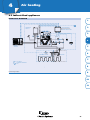
CONNECTOR CENTRAL HEATING WITH
HEAT RECOVERY
7
8
9
Principle demand control
10
CO 2 -SENSOR
Diagram connector central heating with heat recovery
11
PARTS
a Fire stop
b Connector central heating - heat recovery Ø 160 - 80 - 150
c
T-piece 150 - 80 - 150 spiro material insulated
d Renovent HR Medium or Small
e Intergas central heating boiler
f
Thick-walled alu or PP, Ø 80 mm
g PP tube Ø 160 mm, with thermal insulation
h Discharge under ISSO62
CO 2-sensor for Renovent HR with option pcb
32
i
Brink synthetic duct Ø 150 mm
www.brinkclimatesystems.nl Phone +31 522 46 99 44 Fax +31 522 46 94 00
3
Ventilation
3.2 Central ventilation
TECHNICAL INFORMATION
1
CONNECTING DUCTS RENOVENT HR
RENOVENT HR LARGE LEFT-HANDED
To prevent condensation on the outside of the outside air supply duct
2
and the air exhaust duct from the Renovent HR, these ducts must be provided with an external vapour barrier as far as the appliance. It is recommended to connect the ducts from and to the dwelling flexibly to the appliance
using Brink acoustic flexible hose with a minimum length of 1 m. Finished
3
mufflers are available for this purpose.
Brink carries a complete range of synthetic ducts with accessories. The
synthetic duct can easily be mounted and also provides good insulation.
4
The supply ducts system must be designed to comply with NEN 1070 in
nominal setting. Pay attention to crosstalk and installation noise, also for
Connection example
incorporated ducts. If necessary, the supply ducts must be insulated (for instance when they are installed outside the insulated envelope). For a more
5
RENOVENT HR MEDIUM LEFT-HANDED
comprehensive supply ducts system, it is recommended to place control
diffusers in the ducts where necessary.
6
SLEEVES RENOVENT HR
Outdoor air supply preferably comes from the wall. If the outdoor air
7
is taken from under the roof tiles, it must be done from the shadow side of
the dwelling. Condensate formation in the roof deck must be prevented and
no water may run in. In addition, the outdoor air supply duct must be designed to prevent surface condensation. The discharge duct must be taken
through the roof deck in such a manner that no condensate can be formed
8
Connection example
here either. In addition, surface condensation must be prevented when
installing the discharge duct. It is important to always use an insulated ventilation roof sleeve. The location of the mechanical ventilation air discharge
and the sewer vent must be chosen in such a manner that they do not cause
nuisance for the supply. The supply diffusers in the dwelling itself will have
to be located to prevent fouling and draught. In addition, sufficient overflow openings must be installed (see NEN 1087, door gap 20 mm).
PARTS
9
A No sewer vent in the same roof area as the ventilation supply
B Ventilation supply possibility at end roof area
C Preferred location for ventilation and supply
10
D Ventilated ridge construction
E Connect supply and exhaust ducts flexibly insulated, with vapour
barrier
11
F Renovent HR (place level)
G Connect condensate discharge according to installation instructions
H Connect supply and exhaust ducts acoustically insulated
I
Insulated ventilation roof sleeve
33
3
Ventilation
3.2 Central ventilation
RENOVENT HR LEFT-HANDED
1
2
3
4
5
6
Sleeves
SLEEVES
Description
7
1
8
2
Ventilation roof sleeve (exhaust) D125 insulated
Ø 125 mm
Ø 150 mm
Ø 160 mm
Ø 180 mm
< 180 m3/h
< 250 m3/h
250 - 325 m3/h
> 325 m3/h
•
Ventilation roof sleeve (exhaust) D150 insulated
•
Ventilation roof sleeve (exhaust) D166 insulated
•
Ventilation supply (under tiles) D125, insulated
Ventilation roof sleeve (supply) D125 insulated
Ventilation supply (wall) D125 insulated
Acoustic duct D125 (1 m)
•
•
•
Ventilation supply (wall) D180 insulated
5
•
•
Ventilation supply (wall) D150 insulated
11
•
•
Ventilation roof sleeve (supply) D180 insulated
4
•
•
Ventilation roof sleeve (supply) D150 insulated
10
•
•
Ventilation supply (under tiles) D180 insulated
3
•
•
Ventilation supply (under tiles) D150 insulated
9
•
•
Acoustic duct D150 (1 m)
•
Acoustic duct D160 (1 m)
•
Acoustic duct D180 (1.5 m)
6
HR duct D125
•
•
HR duct D150
•
Thermally insulated duct (D160)
•
HR duct D180
7
8
34
•
Adapter 180-150 and connector D150 accessory
•
Adapter 160-150 and connector D150 accessory
•
Adapter 180-160 and connector D180 accessory
•
www.brinkclimatesystems.nl Phone +31 522 46 99 44 Fax +31 522 46 94 00
3
Ventilation
3.2 Central ventilation
RESISTANCE CURVE
RESISTANCE CURVE
1
Each [Pa]
Each [Pa]
40
40
35
35
30
30
25
25
20
15
20
15
10
10
5
5
2
0
0
0
50
100
150
200
250
0
50
100
150
200
250
Q v [m 3/h]
Resistance ventilation supply (wall), D150 insulated
Resistance ventilation supply (under tiles), D150 insulated
RESISTANCE CURVE
RESISTANCE CURVE
Each [Pa]
3
Q v [m 3/h]
4
Each [Pa]
60
5
50
40
30
Supply
Supply
20
6
Exhaust
10
Exhaust
0
0
Resistance ventilation sleeve D125 insulated (supply and exhaust)
Q v [m 3/h]
RESISTANCE CURVE
50
100
150
200
250
300
Q v [m 3/h]
Resistance ventilation roof sleeve, D150 insulated (supply and exhaust)
RESISTANCE CURVE
8
Each [Pa]
Each [Pa]
7
60
50
9
40
30
Supply
20
Exhaust
10
10
D166 insulated, exhaust
0
0
50
100
150
200
250
300
Resistance ventilation roof sleeve, D166 insulated (exhaust)
350
400
Q v [m 3/h]
Q v [m 3/h]
Resistance ventilation roof sleeve, D180 insulated (supply and exhaust)
RESISTANCE CURVE
Each [Pa]
Resistance ventilation supply wall D125 insulated
Q v [m 3/h]
35
11
3
Ventilation
3.2 Central ventilation
3.2.3 AIR COMFORT CONTROL (ACC) DWELLING VENTILATION
1
GENERAL INFORMATION
2
AIR COMFORT CONTROL (ACC)
ACC is a demand controlled ventilation system for dwelling that automatically controls the ventilation rate as required for every habitable room.
3
Suitable air supply units for the ACC system are the Sonair (for wall
mounting) or the Innoventus (for mounting behind a heating radiator).
With its simple installation, ACC offers a unique ventilation concept to
create a healthy and comfortable indoor climate in new as well as existing
buildings at a low energy demand.
4
AIR SUPPLY UNITS
CONTROL PANEL
The Control Panel is the heart of the ACC system. This is where the
required ventilation rates and times and cooking/showering mode can be
WIDELY APPLICABLE IN NEW PROJECTS AND
set. The Control Panel also controls the Extraction Unit.
RENOVATION
5
6
The ACC system for dwellings is a simple and effective method for
EXTENSION WITH CO2-SENSOR
ventilating new and existing buildings at a low energy demand without
The ACC system can be extended with CO2-sensors. These sensors
a complex ventilation ducts system. Every habitable room receives fresh
measure the CO2-content in the habitable room(s) and automatically adapt
outdoor air through distributed mechanical air supply units (Sonair and/or
the quantity of supplied fresh outdoor air. That guarantees the correct
Innoventus) with excellent sound-proofing and air-cleaning characteristics.
ventilation rate and a healthy indoor climate at all times.
The whispering air supply be controlled automatically or set manually on
the Control Panel. A central exhaust unit removes the air through exhaust
7
points in the kitchen, the toilet and the bathroom. The exhaust air rate
stalled ducts system and exhaust diffusers in kitchen, toilet and bathroom.
ventilation.
The ventilation rate of the exhaust is adapted to the air supply rate
through the various air supply units to the habitable rooms of the dwelling.
DEMAND-CONTROLLED VENTILATION
The ACC Control Panel controls the ventilation in every habitable room
separately, if required at moments and flow rates as preprogrammed by
optimise the airflow to keep the air quality at a healthy level.
RF) can be connected to the Extraction Unit to temporarily activate a higher
extraction rate.
NET FILTERS
The ACC system must be fitted with a mains filter to comply with
mandatory EMC requirements. The mains filter keeps the powerline signal
SIMPLE INSTALLATION
The ACC features the unique Powerline Communication system
11
That creates a ventilation balance in the dwelling. A bathroom switch (also
the occupant. In addition, the ventilation can be controlled by sensors in
the room which, based on the ambient carbon dioxide concentration (CO2)
10
The Extraction Unit extracts the air from the dwelling through the in-
is automatically geared for the supply air rate, guaranteeing balanced
8
9
EXTRACTION UNIT
within the dwelling and contributes to reliable communication. The ACC
system must be connected to its own mains group to exclude external inter-
through the electric mains between the ACC components. As a result,
ference sources. The mains filter is available in a surface-mounted version
installation of control cables becomes superfluous, which saves installation
and in version for mounting on a DIN rail.
costs and makes the system suitable for use in existing dwellings.
40
www.brinkclimatesystems.nl Phone +31 522 46 99 44 Fax +31 522 46 94 00
3
Ventilation
3.2 Central ventilation
PHASE COUPLER
AIR BASIC SYSTEM (ABS)
The ACC phase coupler interlinks the Powerline signals from a maxi-
The ABS is a simplified version of the ACC ventilation system, intended
mum of three different mains phases. It is used in existing dwellings where
for dwellings that do not yet have a mechanical extraction system or for
the ACC system components (Sonair, Innoventus, Extractor, Control Panel,
dwellings with humidity problems. A Sonair or Innoventus is installed in the
CO2-sensor, and Extraction Unit) are divided over several phases of the
kitchen and the master bedroom, an Extraction Unit arranges extraction.
1
2
mains installation.
3
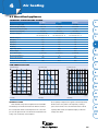
TECHNICAL SPECIFICATIONS AIR SUPPLY UNITS
Appliance type
Sonair A+
Sonair F+
Innoventus
Dimensions H x W x D [mm]
455 x 310 x 134
455 x 310 x 134
370 x 410 x 142
Housing
Synthetic, colour white (RAL 9003)
Synthetic, colour white (RAL 9003)
Metal, colour white (RAL 9010)
230/50
230/50
230/50
Power supply [V~/Hz]
3
Ventilation capacity [dm /s]
3
3
Max. flow rate 62.5 (225 m /h)
Max. flow rate 62.5 (225 m /h)
Max. flow rate 62.5 (225 m3/h)
with G3 filter, continuously adjustable
with G3 filter, continuously adjustable
with G3 and F6 Filter, continuously
4
5
adjustable on the Control Panel
Rated power [W]
3
3
9.6 at 17 dm /s (60 m /h)
9.6 at 17 dm /s (60 m /h)
9.6 at 17 dm3/s (60 m3/h)
52.3 at 62.5 dm3/s (225 m3/h)
52.3 at 62.5 dm3/s (225 m3/h)
52.3 at 62.5 dm3/s (225 m3/h)
+
3
3
+
Sound reduction* (G3 filter,
Sonair A :Dn,e,w= 52 dB
Sonair F :Dn,e,w = 56 dB
sleeve: DV 100F)
(ISO 717-1:1996)
(ISO 717-1:1996)
White mains cable [m]
1.80
1.80
6
Dn,e,w=54 dB (ISO 717-1:1996)
1.80
7
* Based on Peutz test report no. A. 1368
TECHNICAL SPECIFICATIONS SYSTEM ELEMENTS
Control Panel
CO2-sensor
Dimensions (mm]
100 x d 30
100 x d 25
Power supply [V~/Hz]
230/50
230/50
Rated power [W]
Nominal 1.5
Nominal 1.5
Maximum 2.5
Maximum 6.0
8
9
10
TECHNICAL SPECIFICATIONS ACC EXHAUST BOX
ACC exhaust box
Dimensions H x W x D [mm]
260 x 380 x 340
Power supply [V~/Hz]
230/50 (1 phase with europlug)
Sound pressure level* [dB(A)]
28 at 75 m3/h, 20 Pa
11
46 at 225 m3/hour, 150 Pa
Max. 55 at 300 m3/h
Rated power [W]
3
Maximum ventilation capacity [m /h]
440 at 150 Pa
* Sound pressure level in practical setup at 1 metre distance
TECHNICAL DATA MAINS FILTER
63 A
100 A
Dimensions H x W x D [mm]
90 x 72 x 71
138,5 x 105 x 57
Version
DIN rail mounting
Surface-mounted
41
3
Ventilation
3.2 Central ventilation
TECHNICAL DATA WALL SLEEVE
1
2
3
4
Type
DV100
DV100F
Flexible sleeve
Dimension ø x L [mm]
ø100 and L 500
ø 100 en L 500
ø 110 en L 420
TECHNICAL DATA WALL GRILLES
Type
Square synthetic
Round aluminium
Round monumental
Brick size (Waal size)
Size [mm]
125 x 125
ø 100
ø 130
55 x 210
Version
Square synthetic
Round aluminium
Round cast iron
Coated steel
Suitable for
DV100 / flexible sleeve
DV100 / flexible sleeve
DV100 / flexible sleeve
Flexible sleeve
wall sleeve
rond
rond
rond
facing brick
SYSTEM SOUND SONAIR ACC
Appliance Type
5
LI:AK [dB(A)]
LPA:10m [dB(A)]
LI:AK [dB(A)]
LPA:10m2 [dB(A)]
30 m3/h
< 16.0
< 15.0
< 12.5
< 11.5
45 m3/h
< 22.5
< 22.5
< 18.5
< 18.5
60 m /h
28.0
28.5
23.0
23.5
90 m3/h
36.5
38.0
32.5
34.0
47.0
49.5
42.0
43.5
3
140 m /h
7
Sonair F+
Volume rate
3
6
Sonair A+
2
SYSTEM SOUND SONAIR AT 30 DB(A)
Appliance Type
2
LPA:10m dB(A)
Sonair A+
3
63 m /hour
Sonair F+
76 m3/hour
8
9
10
11
42
www.brinkclimatesystems.nl Phone +31 522 46 99 44 Fax +31 522 46 94 00
3
Ventilation
3.2 Central ventilation
3.2.4 FLEXIVENT
1
GENERAL INFORMATION
2
THE FLEXIVENT APPLIANCE
The appliances are made of an ivory polypropylene, talcum-filled
Flexivent has specially been designed for balanced ventilation with
3
4
body containing a counterflow heat exchanger and rpm-controlled EC
heat recovery. The thermal energy in the foul air that is discharged from
motors. The aluminium plate heat exchanger is corrosion resistant and fully
the dwelling is used to heat the fresh, clean outdoor air that is brought in.
recyclable. In addition, the exchanger ensures fully separated air flows and
The heat exchanger transfers 90% of the heat, so it is no longer necessary
a low air-side resistance. The fans have back-bent vanes and vibration-free
to heat the ventilation air.
suspension. The fans have a low sound level, a very low fouling rate, low
Flexivent is a compact ventilation unit. It can be fitted with a full
bypass for ventilation in summer without heat exchange.
rated power, and a stable fan characteristic.
The appliances come with two G3 filters that can easily be taken out
and cleaned by the user himself.
5
FLEXIVENT 300 AND 400
The Flexivent is available in a right-handed and a left-handed version.
Flexivent comes in two versions: Flexivent 300 and 400. These appliances feature an advanced control system with 3-way switch. Every setting
The appliances may optionally be fitted with a complete bypass for ventilation in summer without heat exchange, including automatic control.
is continuously adjustable. In addition, the appliances have automatically
6
AVAILABILITY
controlled frost protection.
The Flexivent is exclusively available through specialised wholesalers.
7
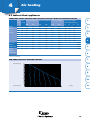
TECHNICAL INFORMATION
FLEXIVENT 300
8
9
Mode
Flow rate [m³/h]
Rated power [W]
Maximum
300
134
High
225
64
Medium
150
31
Low
100
19
Mode
Flow rate [m³/h]
Rated power [W]
Maximum
400
232
High
300
117
FLEXIVENT 400
10
11
Medium
200
45
Low
100
17
46
www.brinkclimatesystems.nl Phone +31 522 46 99 44 Fax +31 522 46 94 00
3
Ventilation
3.2 Central ventilation
FLEXIVENT 300
1
Resistance ducts system [Pa]
FXUYH
2
FXUYH
FXUYH
SUHVVXUHVLGHYHUWLFDO
3
4
5
6
Flow rate [m 3/h]
7
FLEXIVENT 400
Resistance ducts system [Pa]
8
FXUYH
FXUYH
9
FXUYH
SUHVVXUHVLGH
YHUWLFDO
10
11
Flow rate [m 3/h]
47
3
Ventilation
3.3 Distributed ventilation
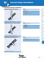
3.3.1 ADVANCE
1
GENERAL INFORMATION
2
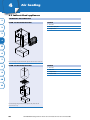
ADVANCE
ADVANCE DESIGN
Advance is a demand-controlled, distributed ventilation unit with heat
3
For wall feed-through a flexible wall sleeve is available with a choice
al buildings. Advance can be used as stand-alone ventilation unit or as ‘‘the
between a surface-mounted grille or a built-in grille in facing brick size.
heart’’ of a hybrid ventilation system.
Advance comes as standard with a mains cable, colour white, RAL 9010. The
Because Advance does not require long air ducts, it is not only suitable
4
for application in new dwellings, but it is also easily retrofitted in renova-
wall grilles are available in the colours RAL 9001, RAL 7016 and Old Iron. A
drilling jig is available as mounting tool.
tion projects, for instance to improve the energy label. Advance comes as
standard with CO2-sensor control, an enthalpy heat exchanger (keeping
5
Advance is composed of a ventilation unit and a wall mounting plate.
recovery for application in habitable rooms of dwellings and non-residenti-
the efficiency optimal, even at low outdoor temperatures) and a built-in
control interface with display. With the enthalphy heat exchanger, a
APPLICATION
The Advance is widely applicable in new projects and existing buildings, including offices, dwellings, health centres and hotels.
condensate discharge is not necessary, because the humidity is transferred/
ADVANCE
maintained.
6
STANDARD FUNCTIONS
• Automatic CO2- and RH control based on the indoor climate
7
• Manual control (Boost)
• Pause
• Increased summer night ventilation (only supply)
8
ADVANCE
A
B
9
indoor
outdoor
10
B
11
Connections and dimensions inclusive of wall mounting plate
A
Basic diagram
KEY
KEY
A Top view
I
To dwelling
A Exhaust foul air from dwelling
B Front view
II
To atmosphere
B Supply clean outdoor air
C Bottom view
III From dwelling
D Side view
IV From atmosphere
E Lead-through mains cable
F On/Off switch
G Service connector
50
www.brinkclimatesystems.nl Phone +31 522 46 99 44 Fax +31 522 46 94 00
3
Ventilation
3.3 Distributed ventilation
TECHNICAL DATA
ADVANCE
Supply voltage [V/Hz]
230/50
Protection degree
IP30
Dimensions inc.. wall mounting plate (B x H x D) [mm]
500 x 1200 x 180
Connection diameters [mm]
2x ø100
Mass (with wall plate) [kg]
31
Filter class
F7 supply air
Ventilation capacity [m3/h]
0 - 150
Rated power [W]
6 - 102
Rated current [A]
0.06 - 0.7
Cos [ij]
0.52 - 0.62
Enthalpy heatexchanger efficiency
80 - 90%
1
2
G3 exhaust air
3
4
5
6
7
8
9
10
11
51
3
Ventilation
3.3 Distributed ventilation
3.3.2 SONAIR STAND-ALONE VENTILATION
1
GENERAL INFORMATION
THE SONAIR
The Sonair is mounted on the inside of an exterior wall. A fan in the
The Sonair ensures constant and controlled supply of fresh, filtered
Sonair sucks in fresh outdoor air through a duct in the exterior wall. The
outdoor air. The Sonair ventilates at a whisper and effectively keeps out
Sonair fan sits in a sound-absorbing chamber, limiting the fan sound and
sounds from outside. In addition, the Sonair prevents unnecessary energy
noise from outside to a minimum. Then the Sonair blows the air through
losses through uncontrolled and excessive ventilation. All this combined
the filter into the room. The flow rate of the supplied outdoor air is set
results in a healthy, comfortable and low-noise indoor climate.
with the aid of push buttons on top of the Sonair that control the fan rpm.
2
3
4
SONAIR
5
6
7
8
9
10
11
TECHNICAL INFORMATION
INSTALLATION
The Sonair can simply be mounted on the inside of an exterior wall.
SONAIR A+ AND SONAIR F+
The Sonair is available as type A+ and F+. Both types ventilate using
An extensive range of wall sleeves, wall grilles and other fittings makes it
100% outdoor air and they have excellent soundproofing qualities. In
possible to install the Sonair at almost any location without affecting the
addition, they have what is known as a diaphragm valve to shut off the air
appearance of the exterior wall.
supply.
53
3
Ventilation
3.3 Distributed ventilation
The Sonair A+ also offers the option of recirculation. The mixing ratio
1
between outdoor air and recirculation air is adjustable. That makes it possible to also clean the indoor air through the built-in filter. That particularly
has a positive effect, for instance, for occupants who have respiratory
2
problems.
SONAIR
3
4
5
6
7
8
9
10
Sonair A + (left) and F + (right)
TECHNICAL SPECIFICATIONS SONAIR A + AND F +
Appliance type
Sonair A+
Sonair F+
Dimensions H x W x D [mm]
455 x 310 x 134
455 x 310 x 134
Housing
Synthetic, colour white (RAL 9003)
Synthetic, colour white (RAL 9003)
Power supply [V~/Hz]
230/50
230/50
Ventilation capacity [dm3/s]
Max. flow rate 62.5 (225 m3/h)
Max. flow rate 62.5 (225 m3/h)
with G3 filter, continuously adjustable
with G3 filter, continuously adjustable
Rated power [W]
9.6 at 17 dm3/s (60 m3/h)
9.6 at 17 dm3/s (60 m3/h)
3
Sound reduction* (G3 filter,
11
3
52.3 at 62.5 dm /s (225 m /h)
52.3 at 62.5 dm3/s (225 m3/h)
Sonair A+:Dn,e,w= 52 dB
Sonair F+:Dn,e,w = 56 dB
sleeve: DV 100F)
(ISO 717-1:1996)
(ISO 717-1:1996)
White mains cable [m]
1.80
1.80
*Based on Peutz test report no. A. 1368
TECHNICAL DATA WALL SLEEVE
Type
DV100
Flexible sleeve
Dimension ø x L [mm]
100 x 500
110 x 420
54
www.brinkclimatesystems.nl Phone +31 522 46 99 44 Fax +31 522 46 94 00
3
Ventilation
3.3 Distributed ventilation
TECHNICAL DATA WALL GRILLES
Type
Square synthetic
Round aluminium
Round monumental
Brick size (Waal size)
Dimension ø [mm]
125 x 125
ø 100
ø 130
55 x 210
Version
Square synthetic
Round aluminium
Round cast iron
Coated steel
Suitable for
DV100 / flexible
DV100 / flexible
DV100 / flexible
Flexible sleeve
wall sleeve
sleeve round
sleeve round
sleeve round
facing brick
1
2
SYSTEM SOUND SONAIR
3
Appliance type
SONAIR A+
FLOW RATE
LI:AK [dB(A)]
LPA:10m2 [dB(A)]
LI:AK [dB(A)]
LPA:10m2[dB(A)]
30 m3/hour
< 16.0
< 15.0
< 12.5
< 11.5
3
45 m /hour
< 22.5
< 22.5
< 18.5
< 18.5
60 m3/hour
28.0
28.5
23.0
23.5
3
36.5
38.0
32.5
34.0
47.0
49.5
42.0
43.5
90 m /hour
3
140 m /hour
SONAIR F+
4
5
SYSTEM SOUND SONAIR AT 30 DB(A)
Appliance Type
2
LPA:10m dB(A)
Sonair A+
3
63 m /hour
6
Sonair F+
76 m3/hour
7
8
9
10
11
55
3
Ventilation
3.3 Distributed
3.4
School ventilation
ventilation
3.4.1 AIR COMFORT CONTROL (ACC) SCHOOL VENTILATION
1
GENERAL INFORMATION
2
CUSTOMISED SOLUTIONS FOR NEW AND
EXISTING SCHOOLS
3
4
DEMAND-CONTROLLED VENTILATION
The ACC School ventilation system is a modular system that ventilates
The ACC School ventilation system is a unique solution for a healthy and
completely demand-controlled. Demand-controlled ventilation on the basis
comfortable indoor climate, combined with energy savings. No matter if
CO2-sensors makes it possible to guarantee the indoor air quality. These
it involves a new building or ventilation improvement in existing school
sensors are built-in in a wall outlet and connected to the 230 V mains. The
buildings.
sensors send measured values to the central control system, on the basis of
which the ventilation supply and exhaust are adjusted in order to realise
VENTILATION SUPPLY
the preset limit values for air quality (CO2-concentration).
Ventilation supply to each classroom is arranged by placing mechanical
5
6
air supply units behind heating radiators (type Innoventus) or on the wall
(type Sonair). These supply units suck in air through a sleeve to be placed
MECHANICAL EXHAUST
Central or distributed mechanical exhaust of indoor air can be realised
in the wall. The air is filtered before it gets into the room. The units are
by a roof fan with 0-10V control. The exhaust rate can be geared for the
connected to the 230 V mains. The supply units have high-quality, acoustic,
ventilation supply per classroom. When using a roof fan or exhaust box,
noise reducing and air filtering properties. The supply rate is controlled
allowance must be made for design and construction of exhaust ducts.
automatically through the central control system.
7
TECHNICAL INFORMATION
8
CENTRAL VENTILATION CONTROL
A central computer with ACC control software steers the demandcontrolled ventilation supply and exhaust for every classroom or space sepa-
9
rately. This computer uses mains modems to communicate through the 230
V mains network with a connected ventilation systems (ventilation supply,
CO2-sensors, mechanical exhaust) in the building. The ventilation control
10
offers various programs and options for ventilation of every classroom or
every space separately:
- Clock- or CO2-controlled ventilation.
- Flushing classrooms for instance during breaks.
11
- Monitoring the air quality in classrooms (CO2-concentration).
- Remote service and maintenance.
Refer to chapter 3.2.3 ACC Dwelling ventilation for further technical
information.
58
www.brinkclimatesystems.nl Phone +31 522 46 99 44 Fax +31 522 46 94 00
3
Ventilation
3.4 School ventilation
3.4.2 RENOVENT HR SCHOOL VENTILATION
1
GENERAL INFORMATION
2
RENOVENT HR SCHOOL VENTILATION
Two sleeves must be installed in the external wall for the supply and
The Renovent HR school ventilation system is designed for improving
3
A beautifully designed, coated duct (standard colour RAL 1013)
simply be retrofitted and fully automatically controls the ventilation flow
ensures optimum distribution of fresh and filtered outdoor air. All other
rate. Increased night ventilation is automatically switched on in summer for
services are placed in the wall cupboard, concealed from view.
For fully automatic control on the basis of indoor air quality, a CO2-
additional cooling of the classroom during the hours of the night.
sensor is available.
4
Central part of the Renovent HR school ventilation system is the fan
unit Renovent HR Large, equipped with bypass and option pcb. Dependent
5
exhaust air.
the interior air quality, particularly in existing classrooms. The system can
For more information please contact Consultancy Department.
on the required ventilation capacity, one or two units are installed in a
sound-absorbing wall cupboard. The wall cupboard can simply be constructed on site from individual panels.
The sound-insulated wall cupboard is not required if the Renovent HR
6
appliances can be installed in an adjacent room (for instance a storeroom).
EXAMPLE SCHOOL VENTILATION
CO 2 -SENSOR
7
a
8
9
e
b
c
10
d
11
Preview of a setup of Renovent HR school ventilation
CO 2-sensor for school ventilation
PARTS
a Supply fresh and heated outdoor air
b Return connection
c
Exhaust ventilation air
d Supply fresh outdoor air fish
e Sound-insulated wall cupboard
62
www.brinkclimatesystems.nl Phone +31 522 46 99 44 Fax +31 522 46 94 00
3
Ventilation
3.5 Other ventilation
3.5.1 DWELLING VENTILATION BOX
1
GENERAL INFORMATION
2
VENTILATION BOX
BRINK DWELLING VENTILATION BOX AC AND DC
The ventilation box is used for mechanical ventilation. The ventilation
housing is made of high-quality, fully recyclable synthetic material. This
3
synthetic material is flame retardant (class B1/B2) and talcum filled. The
spiral housing is made of polystyrene foam. The ventilation box has three
connections at the suction side for ducts with a diameter of 125 mm. As
4
standard, two ducts are capped. The box is available in AC and DC. The
dwelling ventilation box DC is up to 70% more economical than the dwelling ventilation box AC. The fans are equipped with a thermal safety.
5
6
7
TECHNICAL INFORMATION
TECHNICAL SPECIFICATIONS DWELLING VENTILATION BOX AC
8
9
Absence mode
Presence mode
Cooking/showering mode
Air quantity [m /h]
75
150
300
Rated current [A]
0.12
0.16
0.29
Rated power [W]
12
20
65
Mains power (V~/Hz]
1-phase 230/50
1-phase 230/50
1-phase 230/50
3
FAN GRAPH DWELLING VENTILATION BOX AC
10
11
&RRNLQJ
6KRZHUPRGH
3UHVHQFH
PRGH
$EVHQFH
PRGH
66
www.brinkclimatesystems.nl Phone +31 522 46 99 44 Fax +31 522 46 94 00
3
Ventilation
3.5 Other ventilation
TECHNICAL SPECIFICATIONS DWELLING VENTILATION BOX DC
Absence mode
Presence mode
Cooking/showering mode
Air quantity [m /h]
75
200
300
Rated current [A]
0.07
0.16
0.31
Rated power [W]
8
21
41
Mains power (V~/Hz]
1 phase 230-50
1 phase 230-50
1 phase 230-50
3
1
2
FAN GRAPH DWELLING VENTILATION BOX DC
3
4
5
&RRNLQJ
6KRZHUPRGH
6
3UHVHQFH
PRGH
$EVHQFH
PRGH
7
8
INSTALLATION
There are three connection options for the ventilation box:
A: Single speed; the fan will run at one ventilation mode.
B: Dual speed; the fan can be set to presence mode or cooking/showering
mode.
C: Triple speed; the fan can be set to absence mode, presence mode or
For dual and triple control a switchbox will be installed near the
cooker hood in the kitchen. Increasingly, people like to have an additional
switch in the bathroom.
9
The ventilation box comes as standard with a power cord and a Perilex
plug. The preset values for the three ventilation modes can be adjusted on
the ventilation box using potentiometers.
10
cooking/showering mode.
11
67
3
Ventilation
5.1 Direct-fired
3.5
Other ventilation
appliances
3.5.2 ROOF FANS
1
GENERAL INFORMATION
2
THE VERTICAL EXHAUST ROOF FAN
extracting corrosive vapours, the impeller can be optionally be coated to
The housing of the vertical exhaust roof fan is made of high-quality
HDPE (High-Density Poly-Ethylene, RAL 9002), it is 100% recyclable, re-
3
4
make it corrosion-resistant. All fans have been measured under BS 848
item 1.
sistant to all kinds of weather and an insensitive to deformation or failure.
The motor is placed outside the airflow (IP55, insulation class F) and
The housing comes as standard in RAL colour 9002, but other RAL colours
it features a thermocontact (break contact). The maximum permissible
are possible at a small surcharge.
medium temperature is -30/+100 °C. The fan base can be made suitable for
Thanks to the unique ‘mixed flow’ impeller, the vertical exhaust roof
duct connection under the DIN standard.
fan has the highest fan efficiency and the lowest sound level. The fans
come as standard with a protective grill mounted on the exhaust side. For
5
ROOF FAN
A
B
6
7
DIMENSIONS (IN MM]
C
8
E
9
D
Front view roof fan
10
Type
A
B
C
D
E
225
622
466
415
425
40
250
710
540
435
565
40
315
768
588
500
565
40
400
860
640
550
645
40
450
990
740
640
710
50
500
1130
860
690
915
50
ROOF FAN
11
A
DIMENSIONS (IN MM]
B
C
Bottom view roof fan
68
Type
A
B
C
225
75
10.5 (4x)
330
250
100
10.5 (4x)
450
315
100
10.5 (4x)
450
400
120
10.5 (4x)
535
450
120
10.5 (4x)
590
500
180
10.5 (4x)
750
www.brinkclimatesystems.nl Phone +31 522 46 99 44 Fax +31 522 46 94 00
3
Ventilation
5.1 Direct-fired
3.5
Other ventilation
appliances
ROOF FAN
DIMENSIONS (IN MM]
Type
A
B
C
D
E
225
380
370
330
500
200
B
250
530
510
450
500
200
C
315
530
510
450
500
200
400
600
600
535
500
200
450
680
670
590
500
200
500
870
810
750
500
200
Type
F
G
H
I
225
195
321
383
655
250
195
423
485
815
315
195
423
485
815
400
195
513
575
885
450
195
583
645
970
Diameter roof fan
500
195
723
785
1150
ROOF FAN
ROOF OPENING
A
PP
M8 (4x)
LTK
F
E
1
2
3
LDS
max d
KSD
G
H
I
4
5
6
Type
A
B
C
M8 (4x)
PP
F
E
max d
HDS
G
225
340 x 340
250
440 x 440
315
440 x 440
400
530 x 530
450
600 mm
500
740 x 740
7
8
9
DIMENSIONS (IN MM]
Type
A
B
C
225
380
370
330
800
500
250
530
510
450
800
500
315
530
510
450
800
500
400
600
600
535
800
500
I
450
680
670
590
1000
700
J
500
885
810
750
1000
700
Type
F
G
H
I
J
225
495
285
195
285
720
KSD
LTK/o
H
D
E
10
11
Diameter roof fan
250
495
387
195
387
860
315
495
387
195
387
860
400
495
477
195
477
940
450
695
547
195
547
1070
500
695
687
195
687
1350
69
3
Ventilation
3.5 Other ventilation
TECHNICAL DATA VERTICAL EXHAUST ROOF FAN,
1
2
PART 1 (BRINK 225 UP TO AND INCLUDING 450)
Fan
4W
4D
6W
6D
4-4D*
4-8D**
6-6D*
6-12D**
Voltage [V]/Hz]
230/50
3 x 400/50
230/50
3 x 400/50
3 x 400/50
3 x 400/50
3 x 400/50
3 x 400/50
RPM
1400
1400
900
900
1400/1150
1400/700
90/750
900/450
0.09
0.09
0.06
0.06
0.09/0.03
0.18/0.05
0.06/0.03
-
Current [A]
0.80
0.34
0.80
0.30
0.34/0.18
0.75/0.30
0.30/0.12
-
Weight [kg]
12
12
12
12
12
12
12
-
RPM controller
TM2-0.9
TM3-1
TM2-0.9
TM3-1
SD
DS
SD
-
Motor capacity [kW]
0.18
0.18
0.06
0.06
0.18/0.06
0.18/0.05
0.06/0.03
-
Current [A]
1.80
0.63
0.85
0.31
0.63/0.34
0.85/0.35
0.31/0.13
-
Weight [kg]
15
15
15
15
15
15
15
-
RPM controller
TM2-2.2
TM3-1
TM2-0.9
TM3-1
SD
DS
SD
-
Motor capacity [kW]
0.37
0.37
0.09
0.09
0.37/0.12
0.37/0.07
0.09/0.03
-
Current [A]
2.60
1.10
1.20
0.48
1.10/0.59
1.40/0.50
0.48/0.20
-
Weight [kg]
18
18
18
18
18
18
18
-
RPM controller
TM2-3
TM3-2
TM2-2.2
TM3-1
SD
DS
SD
-
Motor capacity [kW]
0.55
0.55
0.18
0.18
0.55/0.18
0.55/0.09
0.18/0.06
0.37/0.075
Current [A]
3.40
1.50
1.90
0.85
1.50/0.80
1.60/0.60
0.85/0.34
1.00/0.44
Weight [kg]
21
21
20
20
21
21
20
21
RPM controller
TM2-4
TM3-2
TM2-2.2
TM3-1
SD
DS
SD
DS
Motor capacity [kW]
-
1.10
0.37
0.37
1.10/0.40
1.10/0.18
0.37/0.18
0.37/0.075
Current [A]
-
2.60
2.80
1.00
2.60/1.40
2.80/1.00
1.00/0.50
1.10/0.45
Weight [kg]
-
26
25
25
26
26
25
26
RPM controller
-
TM3-3
TM2-3
TM3-2
SD
DS
SD
DS
Brink 225
Motor capacity [kW]
3
4
5
Brink 250
Brink 315
6
7
8
Brink 400
Brink 450
9
10
* Two-speed with [ 6-switch:
** Two-speed with Dahlander winding
11
TECHNICAL DATA VERTICAL EXHAUST ROOF FAN,
PART 2 (BRINK 500)
Fan
4D
4d R
6D
4-6D**
4-8D**
6-6D*
6-12D**
Voltage [V]/Hz]
3 x 400/50
3 x 400/50
3 x 400/50
3 x 400/50
3 x 400/50
3 x 400/50
3 x 400/50
RPM
1400
1400
900
1400/1000
1400/700
90/750
900/450
Motor capacity [kW]
2.40
3.00
0.75
3.10/1.10
3.00/0.55
0.75/0.25
0.75/0.15
Current [A]
5.30
7.50
1.90
5.30/3.10
7.30/2.70
1.90/1.00
2.40/1.00
Weight [kg]
40
44
34
40
40
34
34
RPM controller
-
INCL
TM3-2
SD
DS
SD
DS
Brink 500
* Two-speed with [ 6 switch:
** Two-speed with Dahlander winding
70
www.brinkclimatesystems.nl Phone +31 522 46 99 44 Fax +31 522 46 94 00
3
Ventilation
3.5 Other ventilation
ACOUSTIC DATA
Fan
rpm
1
Acoustic capacity suction side (dB Ref. 10-12W) in dB
125 Hz
250 Hz
500 Hz
1 kHz
2 kHz
4 kHz
8 kHz
Brink 225
225/4
1400
50
60
53
59
52
48
37
225/4 + GDB 225
1400
47
53
45
47
36
34
29
225/6
900
41
52
43
49
41
36
29
225/6 + GDB 225
900
38
45
35
37
25
22
21
250/4
1400
59
63
62
64
57
54
37
250/4 + GDB 250
1400
55
56
52
49
41
42
31
250/6
900
50
53
50
55
40
39
29
250/6 + GDB 250
900
46
46
40
40
24
27
23
315/4
1400
61
66
63
64
58
54
40
315/4 + GDB 315
1400
57
59
53
49
42
24
34
315/6
900
52
58
52
55
42
43
31
315/6 + GDB 315
900
48
61
42
40
26
31
25
400/4
1400
68
70
63
68
66
62
45
400/4 + GDB 400
1400
65
63
53
54
51
48
38
400/6
900
57
61
56
62
52
49
33
400/6 + GDB 400
900
54
54
46
48
37
35
26
450/4
1400
71
70
70
72
65
64
48
450/4 + GDB 450
1400
68
64
60
57
49
49
40
450/6
900
62
61
60
62
54
52
36
450/6 + GDB 450
900
59
55
50
47
38
37
28
500/4
1400
81
76
79
76
71
66
54
500/4 + GDB 500
1400
78
70
67
60
54
51
48
500/6
900
71
66
59
65
61
54
44
500/6 + GDB 500
900
68
60
57
49
44
39
38
2
3
Brink 250
4
Brink 315
5
6
Brink 400
7
Brink 450
8
9
Brink 500
10
11
71
3
Ventilation
3.5 Other ventilation
ACOUSTIC DATA
1
ACOUSTIC DATA
Each [mm wk]/[Pa]
Each [mm wk]/[Pa]
2
3
4
5
6
7
8
Vertical exhaust roof fan Brink 225
Q v [m 3/s]/[m 3/h]
Vertical exhaust roof fan Brink 250
ACOUSTIC DATA
ACOUSTIC DATA
Each [mm wk]/[Pa]
Each [mm wk]/[Pa]
Q v [m 3/s]/[m 3/h]
9
10
11
Vertical exhaust roof fan Brink 315
72
Q v [m 3/s]/[m 3/h]
Vertical exhaust roof fan Brink 400
www.brinkclimatesystems.nl Phone +31 522 46 99 44 Fax +31 522 46 94 00
Q v [m 3/s]/[m 3/h]
3
Ventilation
3.5 Other ventilation
ACOUSTIC DATA
ACOUSTIC DATA
Each [mm wk]/[Pa]
1
Each [mm wk]/[Pa]
2
3
4
5
6
Q v [m 3/s]/[m 3/h]
Vertical exhaust roof fan Brink 450
Vertical exhaust roof fan Brink 500
Q v [m 3/s]/[m 3/h]
7
ACOUSTIC DATA
8
'DWDWKURXJKJUDSK
3UHVVXUH
VLGHYHUWLFDO
9
3UHVVXUH
VLGH
KRUL]RQWDO
10
6XFWLRQVLGH
Noise
11
CONTROL SYSTEM
As standard, the vertical exhaust roof fan is adjustable (transformer
and electronic). The control unit is mounted on the roof fan ex factory and
presentative areas. The controller can be operated with a 5-way switch
mounted in a junction box UP50.
The TMA2 is a 5-way controller for 1-phase AC motors intended
it is pre-programmed. The operating switch WS is mounted on the outside
for application in combination with a 5-way thermostat type T55. The
of the fan. There are two versions: a 3-pole version for single speed AC and
transformer in its housing can be placed in a different room than the
three-phase motors and a 6-pole for two-speed three-phase motors (IP65).
thermostat. The controller has an option for manual operation and for
Compared to the WS, the operating switch WST features an extra overload
automatic operation (230 V~/50-60 Hz).
safety.
The TM2 is a 5-way controller for 1-phase AC motors and it has a servo
The TM3 is a 5-way controller for 3-phase motors and it has a
servo contact. The TME3 is similar to the TM3, but specially suitable for
contact 230 V~/0.5 A. The TME2 is the same as the TM2 but the fact that
representative areas. The transformer in its housing can be concealed.
the transformer can be concealed makes the TME2 specially suitable for re-
The controller can be operated with a 5-way switch mounted in a
73
3
Ventilation
3.5 Other ventilation
junction box UP50.
1
Switch SD is a two-speed star-delta switch. DS is a pole number switch
The TMA3 is a 5-way controller for use in combination with a 5-way
that switches the pole number of a two-speed fan with Dahlander motor
thermostat type T55. The controller comes with an open V-switch and the
(Y/YY). Day and night switch boxes are available on request.
housing is splashproof IP54.
2
The controller has a connection for a gas valve on the servomotor
230 V~/50-60 Hz/ 0.5 A, thermal safety and a connection for motor thermo-
3
contacts.
TECHNICAL DATA 5-WAY TRANSFORMERS
4
5
6
Type
Version
Height [mm]
Width [mm]
Depth [mm]
Outer casing
TM2-0.9
230 V/50 Hz/0.9 A
160
135
77
synthetic
TM2-2.2
230 V/50 Hz/2.2 A
160
135
77
synthetic
TM2-3
230 V/50 Hz/3 A
160
135
77
synthetic
TM2-4
230 V/50 Hz/4 A
235
185
158
synthetic
TM3-1
230 V/50 Hz/1 A
235
185
158
synthetic
TM3-2
230 V/50 Hz/2 A
235
185
158
synthetic
TM3-3
230 V/50 Hz/3 A
325
252
168
synthetic
TM3-7
230 V/50 Hz/7 A
300
250
160
metal
Branch voltages 230 V: 0-100-130-160-190-230 V
7
400 V: 0-100-125-150-220-400 V
ELECTRIC CONNECTION
The power cable can be connected directly through an operating
8
9
and the interior is made of sound absorbing synthetic (resistant to + 90 °C).
switch or a motor safety operating switch mounted on the fan. The fan
With the special venturi shape of the sound absorbing material, the muffler
does not have to be dismounted for that purpose.
does not cause pressure loss.
The sound absorbing plate for the suction side of the roof (ADP) is
MOUNTING ACCESSORIES
Mounting the roof fan on a flat roof requires an insulated, glassfibre-
10
under the fan base. The casing is made of sendzimir-galvanised sheet feel
reinforced polyester rooftop fixture (LDS) (RAL 9002). If there is insufficient
mounted under the suction opening in the ceiling. The ADP is made of skinplate RAL 9002, filled with 50 mm glass wool. The sound absorbing plate
can be set at the correct height using adjustable spacer brackets.
space under the roof fixture to place the muffler, the HDS is used. HDS is
the same as LDS, but HDS is used in combination with muffler type GDB.
The muffler (GDB) for the suction side of the fan is placed directly
11
74
www.brinkclimatesystems.nl Phone +31 522 46 99 44 Fax +31 522 46 94 00
3
Ventilation
3.5 Other ventilation
SOUND-ABSORBING PLATES
1
2
4
$GMXVWPHQWKHLJKW
$GMXVWPHQWKHLJKW
3
5
TECHNICAL DATA MUFFLER PLATE
Type
ADP 1100
ADP 1600*
Weight [kg]
Qv m3 max. [m3/h]
6 P bij Qv max. [Pa]
Set height [mm]
6
Muffling in dB at frequency in Hz
125
250
500
1000
2000
4000
22
23
20
15
600
10
40
2
7
12
15
2100
20
65
1
6
11
20
20
16
15
4500
40
90
1
4
7
15
15
13
15
7000
65
115 (max.)
-
2
5
12
11
10
31
7000
60
120
-
2
8
16
14
12
31
16000
60
250 (max.)
-
1
7
8
8
8
7
8
* Supplied in two parts
MOUNTING ACCESSORIES (LTK AND MXH)
The nonreturn air diffuser (LTK) is mounted on the air inlet side. The
The gasket plate (PP) made of weather resistant, closed-cell synthetic
square box with mounting flange is made of sendzimir steel and fitted with
foam is placed between the fan base and accessories as well as mutually
self-closing balanced synthetic diffusers and a protective cage. The diffuser
between accessories.
opens at an air velocity of 2 m/s. If the air velocity is too low, the LTK can at a
surcharge be supplied with a servomotor 230 V~/50 Hz.
The ventilation hood MXH and the roof fan are made of high-quality
9
MOUNTING ACCESSORIES (PP AND KSD)
10
The sliding box section (KSD) is a square box (length 310 mm) used as
extension for LTK and GDB. The KSD is placed from below. A rubber profile
11
provides an effective airtight seal between roof and ceiling.
HDPE and a stainless steel frame. A protective grille is mounted at the top.
The inflow throat is raised relative to the roof to prevent rain ingress.
75
3
Ventilation
3.5 Other ventilation
AIR FLOW RATES CHECK VALVE LTK
1
Check valve LTK
3
Minimum air flow rate [m /h]
2
225
250/135
400
450
500
500
950
1500
1800
3200
PRESSURE LOSSES
PRESSURE LOSSES
Each [mm wk/wa]/[Pa]
Each [mm wk/wa]/[Pa]
3
4
5
6
7
Pressure losses LTK
Q v [m 3/s]/[m 3/h]
Pressure losses MXH
8
9
10
11
76
www.brinkclimatesystems.nl Phone +31 522 46 99 44 Fax +31 522 46 94 00
Q v [m 3/s]/[m 3/h]
3
Ventilation
3.5 Other ventilation
3.5.3 FAN CASING ALLURE
1
GENERAL INFORMATION
2
THE FAN CASING
The fan casing for the Allure B-40 HR(D) is available in Upflow as well
as Downflow version. The fan casing for the Allure B-25 is only available in
3
Upflow. Allure's sheet steel body is epoxy-coated in cream (RAL 1013).
FAN CASING
4
5
6
7
8
9
10
11
Front view fan casing Allure
PARTS
1 Reset button
2 Display
3 Switchbox
4 System fan (for Downflow behind front)
5 Filter
6 Control Panel
7 Connection temperature sensor (T3)
8 Connection mains power: 230 V
80
www.brinkclimatesystems.nl Phone +31 522 46 99 44 Fax +31 522 46 94 00
3
Ventilation
3.5 Other ventilation
TECHNICAL DATA FAN CASING
Technical data
B-25 HR
B-40 HR(D)
Nominal electric rated power [kW]
0.26
0.60
Maximum air flow rate [m3/h]
450 - 2100
750 - 3400
Maximum safety [°C]
100
100
Width [mm]
500
600
Height [mm]
1200
1200
Depth [mm]
740
740
Weight [kg]
55
60
Supply voltage [V~/Hz]
230/50
230/50
Protection degree
IP30
IP30
1
2
3
4
5
6
7
8
9
10
11
81
4
Air heating
4.1 Air heating
CLIMATE OK INDOOR CLIMATE WITH AIR HEATING
Modern dwellings are built with optimum insulation and almost
ADVANTAGES AIR HEATING
•
without any cracks. That saves a lot of energy. But the almost complete eli-
1
You can opt for one system that can do it all: heating,
cooling, ventilating, filtering
mination of unintended ventilation through cracks has an adverse influence
•
An optimum indoor climate in every season
on the indoor environment. Air heating brings a healthy oxygen content,
•
Every room quickly to the required temperature
improved air purity, no dust, and improved humidity control. In short: the
•
Absence of radiators makes for great design freedom
indoor climate is Climate OK.
•
Fresh air 24 hours a day
In addition, air heating offers a constant and pleasant air circulation,
•
Low energy consumption through heat recovery
cosy and warm or refreshingly cool. Heating in winter but also cooling in
•
Ecologically sound
summer. All this is possible with one system for heating, cooling and venti-
•
Very low noise level
lating in every room of the high-efficiency dwelling.
•
Simple control
Application of balanced ventilation with heat recovery is recommended.
•
Low-maintenance
Through a sophisticated heat recovery system, the fresh air takes over the
•
Constant air circulation evenly distributes the heat of other energy
thermal energy from the air that leaves your home. Brink Climate Systems
sources such as solar radiation, fireplace or wood stove, throughout
offers direct-fired and indirect-fired appliances.
the dwelling.
2
3
4
5
Inconspicuous grilles and a simple ducts system suffice to fully benefit
from the advantages of air heating, throughout the dwelling. The intel-
At Brink Climate Systems, corporate social responsibility is the driving
6
ligent control system heats the spaces almost unnoticeably. It operates
force behind all innovation. The environment is very important in this
trouble-free and requires the least possible maintenance.
connection. Air heating in combination with heat recovery results in major
savings on heating costs. And that means economic use of fossil fuels.
7
8
9
10
11
83
4
Air heating
4.2 Indirect-fired appliances
4.2.1 BQLS
1
GENERAL INFORMATION
2
BQLS, BRINK QUALITY OF LIFE SYSTEM
underfloor heating, an electronic air filter and a solar water heater for
BQLS is a modular concept for highly comfortable and energy-friendly
additional hot water comfort. We can also offer a Brink 28/24 HRE central
heating, cooling and ventilating of dwellings. BQLS is built around the
3
4
5
heating appliance.
series Elan Duo 2-zone air heaters. As standard, it has two independently
operating zones for heating or cooling. One for the living zone and one
WIDELY APPLICABLE IN NEW PROJECTS AND
for the sleeping zone. A Renovent HR heat recovery unit recovers the heat
RENOVATION
Its modular design makes BQLS suitable for almost all types of dwel-
from the ventilation air and the heat source is a Brink 36/30 HRE central
heating appliance integrated DHW supply class CW-5. The complete
lings and comfort levels: from mass production to (very) luxurious dwellings
installation is connected to a central control panel, the Climate Master. The
and for new projects as well as renovation and renewal projects. From basic
Climate Master automatically controls all necessary functions for heating,
to all-in comfort systems and everything in between. Extra functionalities
cooling and ventilating. The basic installation can be extended as required
and comfort can also be added when replacing an existing installation.
with many options such as cooling and heating by means of a heat pump,
6
TECHNICAL INFORMATION
AIR HEATERS
7
8
9
Appliance type
Elan Duo 10 2-zone*
Elan Duo 16 2-zone*
Elan 22 Duo 2-zone
Elan 22 Duo 2-zone
zone 1 and 2
zone 1 and 2
zone 1
zone 2
Nominal
Maximum
Nominal
Maximum
Nominal
Maximum
Nominal
Maximum
Air flow rate per zone [m3/h]
350
400
600
750
1000
1200
600
750
Heating capacity per zone [kW]
5.1
5.7
8.4
10.1
12.7
14.6
8.4
10.1
Rated power fan [W]
50
60
80
150
200
350
80
Water temperature range [°C]
70/50
Water connection [mm]
H X W X D [mm]
150
70/50
70/50
22
22
22
22
787 x 678 x 526
967 x 678 x 583
1112 x 768 x 583
1112 x 768 x 583
40
44
48
48
Weight [kg]
10
70/50
* The technical data for zone 1 and 2 are the same for these appliances
HEAT RECOVERY APPLIANCES
11
Renovent HR
Medium
Ventilation capacity at 150 Pa [m3/h]
Maximum 300
Large
Maximum 400
Rated power [W] (dependent on setting)
180 at 300 m /h at 170 Pa)
304 at 400 m3/h at 150 Pa)
Dimension duct connection [mm]
Ø 150 and Ø 160
Ø 160 and Ø 180
H X W X D [mm]
602 x 675 x 420 (met bypass 500)
602 x 675 x 430 (met bypass 510)
Weight [kg]
31
32
Temperature efficiency [%]
95
95
84
3
www.brinkclimatesystems.nl Phone +31 522 46 99 44 Fax +31 522 46 94 00
4
Air heating
4.2 Indirect-fired appliances
TECHNICAL INFORMATION
1
HEAT SOURCE
Brink HRE central heating appliance
36/30 HRE
28/24 HRE
Nom. load upper value [kW]
8.0 - 36.3
7.9 - 33.1
Nom. load lower value [kW]
7.2 - 32.7
7.1 - 29.9
Nom. capacity at 80/60 [kW]
7.1 - 26.3
6.9 - 22.8
Nom. capacity at 50/30 [kW]
7.8 - 27.1
7.6 - 23.4
Use efficiency HR Heating (Hi) [%]
107
107
Use efficiency HR Hot water (Hi) [%]
95.8
93.9
Generation efficiency central heating is EPS (Hs)
0.95
0.95
Annual tap efficiency EPS (Hs)
0.85
0.825
Tap threshold [l/min.]
2
2
Gas mark CW class
5
4
DHW quantity 60 °C [l/min.]
9
7.5
DHW quantity 40 °C (mixed) [l/min.]
15
12.5
Max. DHW temperature [°C]
60
60
Weight [kg]
36
33
W x H x D [mm]
450 x 710 x 240
650 x 450 x 240
Propane version
on request
on request
2
3
4
5
6
7
CLIMATE MASTER
The Climate Master arranges the necessary communication between
AIR HEATER ELAN DUO 2-ZONE AIR HEATER
The room temperature in two zones can be controlled completely inde-
the various installation components. Everything is perfectly geared for
pendently. That way for instance the living and sleeping zones can get their
each other, both technically and aesthetically, which results in a logical and
own temperature control.
8
neatly arranged complete installation. As standard, the Climate Master
offers many control options, ruling out the need for further programming.
THE BQLS BASIC PRINCIPLE BALANCED
For instance, as standard two or four heating zones can be controlled
VENTILATION WITH HEAT RECOVERY
completely independently.
9
The quantity of exhaust indoor air is exactly matched to the quantity
of fresh, clean outdoor air that is supplied, so there is a steady balance.
THE BQLS BASIC PRINCIPLE AIR HEATING
Brink balanced ventilation is combined with heat recovery. A specially
The air heating system gives a constant and pleasant air circulation
developed heat exchanger makes sure that the heat of the exhaust air
throughout the dwelling on the basis of fresh and filtered air. Cosy and
is transferred to the supplied outdoor air. The foul and humid air from
warm in winter and pleasantly cool in summer. The Renovent HR and
bathroom, kitchen and toilet goes out the door and the valuable heat stays
the ventilation provisions ensure that smells and vapours from kitchen,
in. The heat recovery unit Renovent HR keeps 95% of the heath in the
bathroom and toilet are carried off to the atmosphere. The system of conti-
dwelling that otherwise would have gone to waste.
nuous ventilation and filtering keeps the air fresh and unwanted dust particles out of the door. The slowly circulating air quickly brings the dwelling to
the desired temperature. The system is controlled by the Climate Master. It
comes in two versions: the Duo (for 2 zones) and the Multi (for 4 zones).
85
10
11
4
Air heating
4.2 Indirect-fired appliances
THE HEAT RECOVERY UNIT RENOVENT HR
1
Renovent HR has specially been designed for balanced ventilation
with heat recovery. Application of low-energy direct current fans limits
it is layered. The water heater is insulated to limit heat losses. The burner
controller of the Brink Kombi Kompakt HRE comes as standard with water
heater control.
the power consumption to the minimum and makes for a very low-noise
2
The Brink charging water heater together with the Brink HRE central
operation is. The air flow rate is easily adjustable on the display. Standard
heating is the optimum combination. That gives you maximum generation
operation is through a 3-way switch that is usually placed in the kitchen. An
yield because the water heater does not contain an exchanger, but the
additional wireless remote control is optional.
water is directly heated by the Brink HRE central heating appliance.
THE DOUBLE HIGH EFFICIENCY BRINK HRE HOT
INSTALLATION CHARGING WATER HEATER
3
WATER APPLIANCE
4
The inlet and outlet of the Brink charging water heater are marked for
The Brink HRE central heating appliance is based on the Intergas
Kombi Kompakt. This is an appliance with a high efficiency for heating as
simple and error-free installation. We commend to place the Brink charging
water heater not too far from the central heating appliance.
well as a high efficiency for domestic hot water. Its secret is in the unique
5
double two-in-one heat exchanger. This heat exchanger limits heat losses
CHARGING WATER HEATER WITH HIGH-
to the minimum and ensures maximum heat exchange. The central heating
EFFICIENCY CENTRAL HEATING BOILER
water and the cold domestic water flow directly through the heat exchanger to maximally cool the flue gases and optimally utilise the condensation
6
heat.
UNDERFLOOR HEATING
7
Combining the ELAN with underfloor heating ensures increased comfort in rooms with stony floors such as tiles or natural stone. Independently
controlled heating zones, for instance in the living room and bathroom, can
8
also be used with underfloor heating. The underfloor heating can also ‘tag
along’ with the air heating.
9
BQLS IN COMBINATION WITH A HEAT PUMP
BQLS comes as standard with the Brink HRE central heating appliance.
This appliance has a maximum central heating capacity of about 30 kW. For
10
domestic hot water supply the appliance has a capacity of 36 kW. This capacity is mainly required for comfortable domestic hot water supply. If added
to the installation, a heat pump can heat the dwelling for the largest part
of the heating season. That way the heat pump with a relatively low capa-
11
city makes a major contribution to a reduction of the energy consumption
PARTS
A Charging water heater
B Central heating boiler
C Supply by central heating boiler
and CO2-emission.
D Return through central heating boiler
THE BRINK CHARGING WATER HEATER
The Brink charging water heater is made of stainless steel and has
E Water heater sensor DHW
F DHW pump
a capacity of 100 litres. Effective, smooth surface, no sacrificial anode,
G DHW connection
strong and light are the features of the charging water heater. The entire
H Cold water connection
stock can be tapped. The water heater cannot be “fully drained” because
I
86
Inlet combination 8 bar
www.brinkclimatesystems.nl Phone +31 522 46 99 44 Fax +31 522 46 94 00
4
Air heating
5.2 Indirect-fired
4.2
Indirect-fired appliances
appliances
HYDRAULIC DIAGRAM
1
2
932:(56833/<
&20%,%2,/(5
+5(
&(175$/&21752/3$1(/
3
4
&+,//(5
+($73803
5
6
81'(5)/225+($7,1*
%$7+5220
7
&2/':$7(5
&21'(16$7(',6&+$5*(
*$6
8
Hydraulic diagram BQLS
9
10
11
87
4
Air heating
4.2 Indirect-fired appliances
4.2.2 ELAN APPLIANCES GENERAL
1
GENERAL INFORMATION
THE ELAN APPLIANCE
exchanger capacity is geared for a water temperature range of 70/50 °C.
The Elan appliances are indirectly fired air heaters used when hot
The air supply temperature may be 50 °C, but lower temperatures can be
water is the energy carrier (Brink central heating or district heating). Elan
realised with the aid of a mixing diffuser. The heat exchanger is composed
heating/cooling appliances have specially been developed to operate in
of copper tubes with specially designed aluminium baffles. This results
combination with a heat pump.
in optimum heat transfer, while the airside and waterside resistances are
Elan Duo 2-zone appliances can control the temperature independent-
3
minimal.
ly in two zones. ELAN Duo 2-zone appliances feature two heat exchangers
and two fans. That allows either different heating or different cooling of
2
4
VERSIONS
Elan 10 and Elan 25 come in two versions. The Elan Upflow blows out
two zones.
the hot air at the top and the Downflow blows out at the bottom. ELAN
Application of a low-energy fan leads to a low power consumption of
the Elan appliances. The sheet steel body of the air heater is epoxy-coated
in a cream colour (RAL 1013) and it has a dark-blue filter door. The heat
heating/cooling appliances, ELAN SWB appliances and ELAN Duo 2-zone
5
appliances are only available in Downflow version.
ELAN appliances come in a left-handed or right-handed version.
6
OVERVIEW ELAN
1-zone heating
1-zone heating/cooling
ELAN-10 Left-handed (Upflow)
•
ELAN-10 Right-handed (Upflow)
•
ELAN-10 Left-handed (Downflow)
•
ELAN-10 Right-handed (Downflow)
•
ELAN-25 Left-handed (Upflow)
•
ELAN-25 Right-handed (Upflow)
•
ELAN-25 Left-handed (Downflow)
•
ELAN-25 Right-handed (Downflow)
•
ELAN-SWB Left-handed
•
ELAN-SWB Right-handed
•
2-zones heating/cooling
7
8
9
ELAN-10 heating/cooling 1-zone Left-handed
•
ELAN-10 heating/cooling 1-zone Right-handed
•
ELAN-25 heating/cooling 1-zone Left-handed
•
ELAN-25 heating/cooling 1-zone Right-handed
•
10
11
ELAN-10 Duo 2-zone Left-handed
•
ELAN-10 Duo 2-zone Right-handed
•
ELAN-16 Duo 2-zone Left-handed
•
ELAN-16 Duo 2-zone Right-handed
•
ELAN-22 Duo 2-zone Left-handed
•
ELAN-22 Duo 2-zone Right-handed
•
89
4
Air heating
5.1 Direct-fired
4.2
Indirect-fired
appliances
appliances
TECHNICAL INFORMATION
1
EXTENSION WITH RENOVENT HR
Elan Downflow appliances can easily be extended with a Renovent HR
2
with three connections at the top and one at the bottom. The Renovent HR
is placed on top of the Elan. This combines the heating system with balanced ventilation with heat recovery (see also chapter 'Renovent HR’).
With their identical designs, the two appliances together form one
3
optical whole.
respectively. Elan Duo appliances can directly be connected using a ‘22 mm’
line. It is recommended to place stop cocks with couplings directly on the
outside of the appliance in the supply as well as the return lines.
Each branch of the exhaust module or the main duct must be provided
with a control diffuser. In addition, all hot air ducts (including the grille
shoes and the outdoor air duct) must be insulated. To prevent moisture
absorption from the ambient air, the insulation material must be provided
with a moisture barrier. Be sure to lay out the return ducts in such a manner
4
CONTROL SYSTEM
that they do not become sound bridges. That means a straight connection
Elan comes as standard with a modulating control unit for the system
between two rooms is not permitted.
fan. The moment when the system fan rpm begins to increase, depends on
5
the setting. When the air in the appliance has heated up sufficiently, the
temperature sensor sends a signal to the system fan to increase its rpm.
With the modulating control system the Elan can adjust to the optimum operating setting in every situation. The Elan appliances feature a
6
CONNECTING THE RETURN AT THE TOP
Accessories are available for the Elan Downflow and Upflow to realise
the return connections at the top and the bottom. A special filter unit and
various return air units in a variety of sizes are available.
control display on which all settings can be made.
CONNECTION OPTIONS RETURN AIR
INSTALLATION ELAN
7
The return is connected to the right-hand side of the appliance for the
The Elan must be placed as close as possible to the hot water supply
right-handed version. The return is connected to the left-hand side for the
and exhaust. The right-handed version has the water connection and the
left-handed version. Before the outdoor air duct is connected to the return
electric connections to the appliance on the left-hand side.
duct or the acoustic return plate, it must be provided with an adjustment
In addition, the Elan must be placed as centrally as possible relative to
8
diffuser.
the air ducts. Be sure to leave sufficient room for maintenance, at least 1
m free space and 1.80 m headroom at the front of the appliance. The Elan
9
10
(EXTRA) AIR FILTERING
must also remain free from the wall and the ceiling. It is important that
The standard filters for the Elan appliances (class G3) are flat filters.
the air heater is in a frost-free room. If the floor is humid, the air heater
For Elan 10, Elan 25, Elan 10 Duo and Elan 25 Duo a separate filter section is
must be placed above floor level. In addition, it is important to place the
available for an electronic filter (fine dust filter). This fine dust filter is ideal
appliance level.
for people with asthmatic problems.
If the air heater is equipped with an open return, the installation room
must have an open connection with the rest of the dwelling. In that case an
DESIGN SOLUTION INDUSTRIAL
acoustic return plate is necessary.
APPLICATIONS
11
The appliance's power cord with plug is connected to an earthed wall
socket (230 V) that must be easily accessible under all conditions.
The Elan air heater and the air nozzle have been combined to develop a high-efficiency solution for heating large assembly spaces, shops,
showrooms, workshops and warehouses. The relatively simple installation
CONNECTING DUCTS
options offer ample industrial application options for heating well-insulated
A standard output module is available for the Elan. It is placed under
the appliance. The various ducts are connected to this output module. The
industrial and business buildings. You will find more information in the
chapter ‘Allure’.
heat exchanger in the Elan is connected using a ¾" and a 1" connection
90
www.brinkclimatesystems.nl Phone +31 522 46 99 44 Fax +31 522 46 94 00
4
Air heating
5.1 Direct-fired
4.2
Indirect fired
appliances
appliances
EASE OF VENTILATION, ENERGY ECONOMY AND
1
EPS GAIN
If an air heater is installed in combination with a Renovent HR, adding
a CO2-sensor in the return air flow enables demand-controlled ventilation.
2
Moreover, this feature creates additional EPS gains of about 0.06. For that
purpose Renovent HR must be equipped with an option pcb.
3
DEMAND CONTROL
([KDXVWWRDWPRVSKHUH
4
2XWGRRUDLUVXSSO\
5
&26HQVRU
6
7
8
9
10
Principle demand control
11
91
4
Air heating
4.2 Indirect-fired appliances
4.2.3 ELAN DUO
1
GENERAL INFORMATION
2
ELAN 10 DUO 2-ZONE
SLEEVES
a Sleeve condensate discharge heat recovery
b Sleeve power cable 230V
c
3
Water connection return
d Water connection supply
e Input opening return air, 399 x 327 mm
f
4
Nozzle opening zone 1 and zone 2, 389 x 216 mm (2x)
g Connection heat recovery (if applicable)
h Sleeve condensate discharge heat recovery (if applicable)
j
5
Sleeve condensate discharge Elan Duo
k Sleeve cable option
6
7
Elan 10 Duo, 2-zone R
ELAN 10 DUO 2-ZONE
PARTS
1 Sleeve condensate discharge heat recovery (if applicable)
8
2 Sleeve power cable 230V
3 Switchbox with dual control unit
4 Control Panel
9
5 Water connection (return)
6 Return temperature sensor
7 Water connection (supply)
10
8 Filter door
9 System fans
10 Filter
11
11 Heat exchanger
12 System temperature sensors
Front view Elan 10 Duo, 2-zone R
92
13 Sleeve condensate discharge
www.brinkclimatesystems.nl Phone +31 522 46 99 44 Fax +31 522 46 94 00
4
Air heating
4.2 Indirect-fired appliances
ELAN 16 DUO 2-ZONE
SLEEVES
1
a Sleeve condensate discharge heat recovery
b Sleeve power cable 230V
c
Water connection return
d Water connection supply (zone 1 and zone 2)
2
e Input opening return air, 470 x 433 mm
f
Nozzle opening zone 1 and zone 2, 456 x 216 mm (2x)
g Connection heat recovery (if applicable)
3
h Sleeve condensate discharge heat recovery (if applicable)
j
Sleeve condensate discharge Elan Duo
k Sleeve cable option
4
5
6
Elan 16 Duo, 2-zone R
ELAN 16 DUO 2-ZONE
PARTS
1 Sleeve condensate discharge heat recovery (if applicable)
7
2 Sleeve power cable 230V
3 Switchbox with dual control unit
4 Control Panel
8
5 Water connection (return)
6 Return temperature sensor
7 Water connection (supply)
9
8 Filter door
9 System fans
10 Filter
10
11 Heat exchanger
12 System temperature sensors
13 Sleeve condensate discharge
11
Front view Elan 16 Duo, 2-zone R
93
4
Air heating
4.2 Indirect fired appliances
ELAN 22 DUO 2-ZONE
1
SLEEVES
a Sleeve condensate discharge heat recovery
b Sleeve power cable 230V
c
Water connection return
d Water connection supply
2
e Input opening return air, 578 x 470 mm
f1 Nozzle opening zone 1, 456 x 306 mm
f2 Nozzle opening zone 2, 456 x 216 mm
3
g Connection heat recovery (if applicable)
h Sleeve condensate discharge heat recovery (if applicable)
j
4
Sleeve condensate discharge Elan Duo
k Sleeve cable option
5
6
Elan 22 Duo, 2-zone R
ELAN 22 DUO 2-ZONE
PARTS
1 Sleeve power cable 230V
7
2 Sleeve condensate discharge heat recovery (if applicable)
3 Control panel zone 1
4 Control panel zone 2
8
5 Return temperature sensor
6 Water connection (return)
7 Water connection (supply)
9
8 System temperature sensor
9 Sleeve condensate discharge
10 Filter door
10
11 Switchbox with 2 x control unit
12 System fans
13 Filter
11
14 Heat exchanger
Front view Elan 22 Duo, 2-zone R
94
www.brinkclimatesystems.nl Phone +31 522 46 99 44 Fax +31 522 46 94 00
4
Air heating
4.2 Indirect fired appliances
TECHNICAL SPECIFICATIONS ELAN 10 DUO AND ELAN 16 DUO 2-ZONE
Appliance type
Elan Duo 10 2-zone
1
Elan Duo 16 2-zone
Nominal
Maximum
Nominal
Maximum
Air flow rate [m3/h]
350
400
600
750
Heating capacity [kW]
5.1
5.7
8.4
10.1
Water capacity [l/h]
222
248
366
440
Waterside resistance [kPa]
0.5
0.7
0.4
0.5
Rated power fan [W]
50
60
80
150
Water temperature range [°C]
70/50
70/50
70/50
70/50
Air supply temperature [°C]
18
18
18
Supply voltage [V~/Hz]
3
18
230/50
230/50
Maximum operating pressure exchanger [bar]
6
6
Water capacity exchanger [l]
2
3
IP20
IP20
Water connection socket joint [mm]
22
22
Weight [kg]
40
44
Protection degree
2
4
5
6
TECHNICAL SPECIFICATIONS ELAN 22 DUO 2-ZONE
Appliance type
Elan 22 Duo 2-zone
Nominal per zone 1
3
Maximum per zone 1
Nominal per zone 2
Maximum per zone 2
Air flow rate [m /h]
1000
1200
600
750
Heating capacity [kW]
12.7
14.6
8.4
10.1
Water capacity [l/h]
552
634
366
440
Waterside resistance [kPa]
0.8
1.0
0.4
0.5
Rated power fan [W]
200
350
80
150
Water temperature range [°C]
Air supply temperature [°C]
Supply voltage [V~/Hz]
Maximum operating pressure exchanger [bar]
Water capacity exchanger [l]
Protection degree
70/50
70/50
18
18
230/50
230/50
6
6
3
3
IP20
IP20
Water connection socket joint [mm]
22
22
Weight [kg]
48
48
7
8
9
10
11
95
4
Air heating
4.2 Indirect-fired appliances
CAPACITY TABLE HEATING AND COOLING CAPACITY PER ZONE
1
ELAN DUO 10 2-ZONE
Water
in [°C]
out [°C] 300
2
3
6
Power levels at different
300
350
350
400
400
return air temperatures [°C]
[kW]
[l/h]*
[kW]
[l/h]*
[kW]
[l/h]*
16
20
22
28
Heating
70
50
4.5
195
5.1
222
5.7
248
+5%
-5%
-10%
Return air:
55
45
3.3
289
3.8
331
4.3
371
+6%
-5%
-10%
18 °C
50
40
2.8
244
3.2
278
3.6
312
+8%
-8%
-16%
RH** 50%
50
35
2.6
148
2.9
168
3.2
187
+10%
-8%
-16%
45
35
2.3
198
2.6
226
2.9
252
+10%
-8%
-16%
40
33
1.9
236
2.2
270
2.5
302
+11%
-10%
-20%
35
30
1.5
257
1.7
294
1.9
329
+15%
-13%
-26%
30
26
1.1
308
1.2
252
1.3
281
+20%
-19%
-38%
Free cooling
14
17
0.8
241
1.0
275
1.1
308
+30%
Return air:
12
16
1.0
212
1.1
242
1.3
270
+35%
24°C RH** 50%
10
14
1.1
239
1.4
290
1.5
325
+40%
Cooling
6
12
1.7
247
1.9
277
2.1
305
+40%
4
5
Air flow rate in [m3/h] per zone
Water
Return air:
24°C RH** 50%
* Water capacity
7
** RH = Relative Humidity
CAPACITY TABLE HEATING AND COOLING CAPACITY PER ZONE
8
9
10
ELAN DUO 16 2-ZONE
Air flow rate in [m3/h] per zone
Water
Water
in [°C]
out [°C] 400
Power levels at different
400
600
600
750
750
return air temperatures [°C]
[kW]
[l/h]*
[kW]
[l/h]*
[kW]
[l/h]*
16
20
22
28
Heating
70
50
6.0
260
8.4
366
10.1
440
+5%
-5%
-10%
Return air:
55
45
4.5
387
6.4
551
7.7
665
+8%
-8%
-16%
18 °C
50
40
3.8
326
5.3
461
6.4
555
+8%
-8%
-18%
RH** 50%
50
35
3.4
196
4.7
272
5.6
325
+10%
-9%
-16%
45
35
3.1
264
4.3
371
5.2
445
+10%
-10%
-20%
40
33
2.6
315
3.6
445
4.3
535
+12%
-11%
-22%
35
30
2.0
343
2.8
486
3.4
585
+15%
-14%
-28%
30
26
1.4
294
1.9
413
2.3
496
+18%
-20%
-40%
Free cooling
14
17
1.1
321
1.6
452
1.9
543
+30%
Return air:
12
16
1.3
281
1.8
395
2.2
472
+35%
24°C RH** 50%
10
14
1.6
338
2.2
477
2.7
572
+40%
Cooling
6
12
2.2
318
3.0
426
3.5
496
+40%
11
Return air:
24°C RH** 50%
* Water capacity
** RH = Relative Humidity
96
www.brinkclimatesystems.nl Phone +31 522 46 99 44 Fax +31 522 46 94 00
4
Air heating
4.2 Indirect-fired appliances
CAPACITY TABLE HEATING AND COOLING CAPACITY PER ZONE ELAN 22 DUO
1
2-ZONE (ONLY FOR ZONE 1) (FOR ZONE 2, SEE ELAN 16 DUO)
Water in [°C]
Water out [°C]
Capacity zone 1
Water capacity lh
at 1000 [m3/h] kW
Capacity zone 1 at Water capacity lh
1200 [m3/h] kW
Heating
70
50
12.7
552
14.6
634
Return air:
55
45
9.7
840
11.2
969
18 °C
50
40
8.1
699
9.3
805
RH 50%
50
35
7.0
404
8.0
461
45
35
6.5
557
7.4
640
40
33
5.5
672
6.3
774
35
30
4.3
736
4.9
847
30
26
2.9
622
3.3
714
Free cooling
14
17
2.4
681
2.7
783
Return air:
12
16
2.8
590
3.2
678
18 °C RH 50%
10
14
3.3
719
3.9
827
Heating
6
12
4.2
596
4.7
666
2
3
4
5
Return air:
6
24 °C RH 50%
CAPACITY TABLE HEATING AND COOLING CAPACITY PER ZONE
ELAN 22 DUO 2-ZONE
7
Water
Water
Capacity zone 2
Water-
in [°C]
out [°C]
at 400 [m3/h] kW capacity lh
Heating
70
50
6.5
Return air:
55
45
18 °C
50
RH 50%
50
Capacity zone 2
Water-
Capacity zone 2
Water-
at 600 [m3/h] kW capacity lh
750 [m3/h] kW
capacity lh
260
8.4
366
10.1
440
4.7
387
6.4
551
7.7
665
40
4.0
326
5.3
461
6.4
555
35
3.9
196
4.7
272
5.6
325
45
35
3.3
264
4.3
371
5.2
445
40
33
2.7
315
3.6
445
4.3
535
35
30
2.1
343
2.8
486
3.4
585
30
26
1.5
294
1.9
413
2.3
496
Free cooling
14
17
1.2
321
1.6
452
1.9
543
Return air:
12
16
1.4
281
1.8
395
2.2
472
18 °C RH 50%
10
14
1.9
338
2.2
477
2.7
572
Heating
6
12
2.7
426
3.0
426
3.5
496
8
9
10
11
Return air:
24 °C RH 50%
97
4
Air heating
4.2 Indirect-fired appliances
FAN GRAPH ELAN 10 DUO 2-ZONE ELAN 16 DUO 2-ZONE
1
Each External [Pa]
2
3
4
Volume flow rates
500
475
450
425
400
375
350
325
300
275
250
225
200
175
150
125
100
75
50
25
0
100
150
200
250
300
350
400
450
500
550
600
650
700
750
800
850
900
Q v [m 3/h]
950
5
FAN GRAPHS ELAN 22 DUO 2-ZONE
6
Each External [Pa]
7
8
9
Volume flow rates
zone 1
675
650
625
600
575
550
525
500
475
450
425
400
375
350
325
300
275
250
225
200
175
150
125
100
75
50
25
0
100
250
400
550
700
850
1000
1150
1300
Q v [m 3/h]
10
Each External [Pa]
11
Volume flow rates
500
475
450
425
400
375
350
325
300
275
250
225
200
175
150
125
100
75
50
25
0
100
150
200
250
300
350
400
450
500
550
600
650
700
750
800
850
900
950
Q v [m 3/h]
zone 2
98
www.brinkclimatesystems.nl Phone +31 522 46 99 44 Fax +31 522 46 94 00
4
Air heating
4.2 Indirect-fired appliances
ELAN DUO 10 2-ZONE
PARTS
1
A Air heater
C Acoustic return plate
E Output module
2
3
4
5
6
Elan 10 Duo Downflow 2-zone with output module and return at the side
ELAN DUO 16 2-ZONE
PARTS
7
A Air heater
C Acoustic return plate
E Output module
8
9
10
11
12
Elan 16 Duo Downflow 2-zone with output module and return at the side
13
14
99
4
Air heating
4.2 Indirect-fired appliances
ELAN 22 DUO 2-ZONE
1
PARTS
A Air heater
C Acoustic return plate
E Output module
2
3
4
5
6
Elan 22 Duo Downflow 2-zone with output module and return at the side
7
8
9
10
11
100
www.brinkclimatesystems.nl Phone +31 522 46 99 44 Fax +31 522 46 94 00
4
Air heating
4.2 Indirect-fired appliances
4.2.4 ELAN HEATING/COOLING
1
GENERAL INFORMATION
2
ELAN 10 HEATING/COOLING
SLEEVES
a Sleeve condensate discharge heat recovery (if applicable)
b Sleeve power cable 230V
c
3
Water connection (return) Ø 22
d Water connection (supply) Ø 22
e Input opening return air, 399 x 325 mm
f
4
Exhaust opening, 389 x 202 mm (2x)
g Connection supply air heat recovery (only if applicable)
h Sleeve condensate discharge heat recovery (if applicable)
j
5
Sleeve condensate discharge
k Sleeve cable option
6
7
Elan 10 heating/cooling R
ELAN 10 HEATING/COOLING
PARTS
1 Sleeve condensate discharge heat recovery (if applicable)
8
2 Sleeve power cable 230V
3 Switchbox with control unit
4 Control Panel
9
5 Water connection (return) Ø 22
6 Return temperature sensor
7 Water connection (supply) Ø 22
10
8 Filter door
9 System fan
10 Filter
11
11 Heat exchanger
12 System temperature sensor
13 Sleeve condensate discharge
Front view Elan 10 heating/cooling R
104
www.brinkclimatesystems.nl Phone +31 522 46 99 44 Fax +31 522 46 94 00
4
Air heating
4.2 Indirect fired appliances
ELAN 25 HEATING/COOLING
SLEEVES
1
a Sleeve condensate discharge heat recovery (if applicable)
b Sleeve power cable 230V
c
Water connection (return) Ø 22
d Water connection (supply) Ø 22
2
e Input opening return air, 470 x 575 mm
f
Exhaust opening, 456 x 214 mm (2x)
g Connection supply air heat recovery (only if applicable)
3
h Sleeve condensate discharge heat recovery (if applicable)
j
Sleeve condensate discharge
k Sleeve cable option
4
5
Elan 25 heating/cooling R
ELAN 25 HEATING/COOLING
6
PARTS
1 Sleeve condensate discharge heat recovery (if applicable)
2 Sleeve power cable 230V
3 Switchbox with control unit
7
4 Control Panel
5 Water connection (return) Ø 22
6 Return temperature sensor
8
7 Water connection (supply) Ø 22
8 Filter door
9 System fan
9
10 Filter
11 Heat exchanger
12 System temperature sensor
10
13 Sleeve condensate discharge
11
Front view Elan 25 heating/cooling R
105
4
Air heating
4.2 Indirect-fired appliances
GENERAL INFORMATION
1
TECHNICAL SPECIFICATIONS ELAN HEATING/COOLING
Appliance type
Elan 10 heating/cooling
2
3
3
4
Maximum
Nominal
Maximum
Air flow rate [m /h]
650
800
1800
2200
Heating capacity [kW]
9.6
11.4
23.4
27.2
Water capacity [l/h]
418
496
1018
1188
Waterside resistance [kPa]
0.6
0.8
0.66
0.9
Rated power fan [W]
80
150
315
Water temperature range [°C]
Air supply temperature [°C]
Maximum operating pressure exchanger [bar]
6
460
70/50
Supply voltage [V~/Hz]
5
Elan 25 heating/cooling
Nominal
70/50
18
18
230/50
230/50
6
6
Water capacity exchanger [l]
3.5
6
Protection degree
IP20
IP20
Water connection socket joint [mm]
22
22
Weight [kg]
40
65
CAPACITIES TABLE HEATING AND COOLING CAPACITY ELAN 10 HEATING/COOLING
8
9
Air flow rate 650 [m3/h]
Air flow rate 800 [m3/h]
Water
in [°C]
out [°C]
[kW]
[l/h]*
[kW]
[l/h]*
[kW]
[l/h]*
16
20
22
Heating
70
50
7.6
332
9.6
418
11.4
496
+5%
-5%
-10%
Return air:
55
45
5.7
492
7.1
620
8.5
742
+5%
-5%
-10%
18 °C
50
35
4.4
254
5.5
316
6.5
374
+5%
-5%
-10%
RH** 50%
50
40
4.8
416
6.0
522
7.2
624
+5%
-5%
-10%
45
35
3.9
338
4.9
424
5.8
504
+5%
-5%
-10%
40
33
3.3
402
4.1
506
4.9
604
+5%
-5%
-10%
35
30
2.5
438
3.2
552
3.8
658
+5%
-5%
-10%
30
26
1.7
376
2.2
472
2.6
526
+5%
-5%
-10%
Free cooling
14
17
1.4
416
1.8
518
2.1
616
+30%
Return air:
12
16
1.7
362
2.1
454
2.5
540
+20%
24°C RH** 50%
10
14
1.9
418
2.4
506
3.0
650
+15%
Cooling
6
12
2.3
430
2.9
524
3.4
610
+20%
10
11
Air flow rate 500 [m3/h]
Water
7
Power levels at different
return air temperatures [°C]
Return air:
24°C RH** 50%
* Water capacity
** RH = Relative Humidity
106
www.brinkclimatesystems.nl Phone +31 522 46 99 44 Fax +31 522 46 94 00
28
4
Air heating
4.2 Indirect-fired appliances
CAPACITIES TABLE HEATING AND COOLING CAPACITY ELAN 25 HEATING/COOLING
Air flow rate 1200 [m3/h]
Air flow rate 1800 [m3/h] Air flow rate 2200 [m3/h]
1
Water
Water
Power levels at different
in [°C]
out [°C]
[kW]
[l/h]*
[kW]
[l/h]*
[kW]
[l/h]*
16
20
22
Heating
70
50
16.4
732
23.4
1018
27.2
1188
+5%
-5%
-10%
Return air:
55
40
11.6
670
16.0
925
18.7
1080
+5%
-5%
-10%
18 °C
50
38
10.2
736
14.1
1020
16.5
1190
+5%
-5%
-10%
RH** 50%
50
35
9.4
544
12.9
746
15.0
866
+5%
-5%
-10%
45
35
8.6
742
11.9
1028
13.9
1198
+5%
-5%
-10%
40
33
7.2
990
10.0
1238
11.7
1444
+5%
-5%
-10%
35
30
5.6
972
7.9
1354
9.2
1586
+5%
-5%
-10%
30
26
3.8
825
5.3
1146
6.2
1338
+5%
-5%
-10%
Free cooling
14
17
3.2
904
4.4
1256
5.1
1466
+35%
Return air:
12
16
3.7
790
5.1
1090
6.4
1270
+30%
24°C RH** 50%
10
14
4.4
954
6.1
1324
7.2
1548
+20%
Cooling
6
12
5.0
852
6.9
1116
8.0
1254
+20%
return air temperatures [°C]
28
2
3
4
5
Return air:
6
24°C RH** 50%
* Water capacity
** RH = Relative Humidity
FAN GRAPH ELAN 25 HEATING/COOLING
Each External [Pa]
Volume flow rates
675
650
625
600
575
550
525
500
475
450
425
400
375
350
325
300
275
250
225
200
175
150
125
100
75
50
25
0
100
7
8
9
10
400
700
1000
1300
1600
1900
2200
11
Q v [m 3/h]
107
4
Air heating
4.2 Indirect-fired appliances
TECHNICAL INFORMATION
1
ELAN 10 HEATING/COOLING
PARTS
A Air heater
C Acoustic return plate
2
E Output module
3
4
5
6
7
Elan 10 heating/cooling Downflow with output module and return at the side
8
ELAN 10 HEATING/COOLING
PARTS
A Air heater
B Filter unit
E Output module
9
G Return air unit
10
11
Elan 10 heating/cooling Downflow with output module, filter unit and
return air unit on top
108
www.brinkclimatesystems.nl Phone +31 522 46 99 44 Fax +31 522 46 94 00
4
Air heating
4.2 Indirect-fired appliances
ELAN 25 HEATING/COOLING
PARTS
1
A Air heater
C Acoustic return plate
E Output module
2
3
4
5
6
Elan 25 heating/cooling Downflow with output module and return at the side
7
ELAN 25 HEATING/COOLING
PARTS
A Air heater
B Filter unit
8
E Output module
G Return air unit
9
10
11
Elan 25 heating/cooling Downflow with output module, filter unit and
return air unit on top
109
4
Air heating
4.2 Indirect-fired appliances
4.2.5 ELAN
1
TECHNICAL INFORMATION
2
ELAN 10
SLEEVES
a Sleeve condensate discharge heat recovery (if applicable)
b Sleeve power cable 230V
c
3
Water connection (return), ¾" female
d Water connection (supply), ¾" female
e Input opening return air, 319 x 497 mm
f
4
Exhaust opening, 320 x 465 mm
g Connection input air heat recovery (if applicable)
h Sleeve condensate discharge heat recovery (if applicable)
5
6
7
Elan 10 Downflow R
ELAN 10
8
9
10
11
Elan 10 Upflow R
112
www.brinkclimatesystems.nl Phone +31 522 46 99 44 Fax +31 522 46 94 00
4
Air heating
4.2 Indirect-fired appliances
ELAN 10
PARTS
1
1 Sleeve condensate discharge heat recovery (if applicable)
2 Sleeve power cable 230V
3 Switchbox with control unit
4 Control Panel
2
5 Water connection (return), ¾" female
6 Return temperature sensor
7 Water connection (supply), ¾" female
3
8 Filter door
9 System fan
10 Filter
4
11 Heat exchanger
12 System temperature sensor
5
Front view Elan 10 Downflow R cross-section
6
ELAN 10
7
8
9
10
11
Front view Elan 10 Upflow R cross-section
113
4
Air heating
4.2 Indirect-fired appliances
ELAN 25
1
SLEEVES
a Sleeve condensate discharge heat recovery (if applicable)
b Sleeve power cable 230V
c
Water connection (return), 1" female
d Water connection (supply), 1" female
2
e Input opening return air, 470 x 575 mm
f
Exhaust opening, 440 x 550 mm
g Connection input air heat recovery (if applicable)
3
h Sleeve condensate discharge heat recovery (if applicable)
4
5
Elan 25 Downflow R
6
ELAN 25
7
8
9
10
11
Elan 25 Upflow R
114
www.brinkclimatesystems.nl Phone +31 522 46 99 44 Fax +31 522 46 94 00
4
Air heating
4.2 Indirect-fired appliances
ELAN 25
PARTS
1
1 Sleeve condensate discharge heat recovery (if applicable)
2 Sleeve power cable 230V
3 Switchbox with control unit
4 Control Panel
2
5 Water connection (return), 1" female
6 Return temperature sensor
7 Water connection (supply), 1" female
3
8 Filter door
9 System fan
10 Filter
4
11 Heat exchanger
12 System temperature sensor
5
Front view Elan 25 Downflow R cross-section
6
ELAN 25
7
8
9
10
11
Front view Elan 25 Upflow R cross-section
115
4
Air heating
4.2 Indirect-fired appliances
TECHNICAL SPECIFICATIONS ELAN
1
Appliance type
Elan 10
Elan 25
Nominal
3
2
3
4
Nominal
Maximum
Air flow rate [m /h]
650
800
1800
2200
Heating capacity [kW]
8.7
10.2
21.9
25.4
Water capacity [l/h]
378
445
956
1108
Waterside resistance [kPa]
1.7
2.3
2.24
2.94
Rated power fan [W]
80
150
315
460
Water temperature range [°C]
70/50
70/50
70/50
70/50
Air supply temperature [°C]
18
18
18
Supply voltage [V~/Hz]
18
230/50
230/50
Maximum operating pressure exchanger [bar]
16
16
Water capacity exchanger [l]
2
3.26
IP30
IP30
Protection degree
5
Maximum
Water connection (female thread) ["]
¾
1
Weight [kg]
32
62
6
CORRECTION FACTOR HEATING CAPACITY ELAN 10 AT OTHER WATER AND AIR INPUT
TEMPERATURES
7
Water temperature range [°C]
Air supply temperature [°C]
Nominal
8
9
Maximum
+16
+18
+20
+22
+16
+18
+20
+22
90/70
1.54
1.49
1.44
1.38
1.56
1.50
1.45
1.39
90/50
1.29
1.23
1.17
1.11
1.27
1.22
1.17
1.11
70/50
1.05
1.00
0.94
0.90
1.05
1.00
0.95
0.89
50/35
0.61
0.56
0.51
0.46
0.62
0.56
0.51
0.46
CORRECTION FACTOR HEATING CAPACITY ELAN 25 AT OTHER WATER AND
10
AIR INPUT TEMPERATURES
Water temperature range [°C]
Air supply temperature [°C]
Nominal
11
Maximum
+16
+18
+20
+22
+16
+18
+20
+22
90/70
1.58
1.53
1.47
1.42
1.59
1.54
1.48
1.42
90/50
1.26
1.20
1.14
1.08
1.25
1.19
1.13
1.07
70/50
1.05
1.00
0.95
0.89
1.06
1.00
0.94
0.89
50/35
0.61
0.55
0.50
0.44
0.60
0.55
0.49
0.44
116
www.brinkclimatesystems.nl Phone +31 522 46 99 44 Fax +31 522 46 94 00
4
Air heating
4.2 Indirect-fired appliances
FAN GRAPH ELAN 10
Each External [Pa]
Volume flow rates
500
475
450
425
400
375
350
325
300
275
250
225
200
175
150
125
100
75
50
25
0
100
1
2
3
4
150
200
250
300
350
400
450
500
550
600
650
700
750
800
850
900
950
Q v [m 3/h]
5
FAN GRAPH ELAN 25
Each External [Pa]
Volume flow rates
675
650
625
600
575
550
525
500
475
450
425
400
375
350
325
300
275
250
225
200
175
150
125
100
75
50
25
0
100
6
7
8
400
700
1000
1300
1600
1900
2200
9
Q v [m 3/h]
10
11
117
4
Air heating
4.2 Indirect-fired appliances
ELAN 10
PARTS
1
A Air heater
C Acoustic return plate
D Replacement base
E Output module
2
3
4
5
6
7
Elan 10 Upflow with output module and return at the side
ELAN 10
PARTS
A Air heater
8
B Filter unit
D Replacement base
E Output module
9
10
11
Elan 10 Upflow with output module and return with filter unit at the bottom
118
www.brinkclimatesystems.nl Phone +31 522 46 99 44 Fax +31 522 46 94 00
4
Air heating
4.2 Indirect-fired appliances
ELAN 10
PARTS
1
A Air heater
C Acoustic return plate
D Replacement base
F Connection frame for hot air unit
2
G Hot air unit
3
4
5
6
Elan 10 Upflow with hot air unit and return at the side
ELAN 10
7
PARTS
A Air heater
8
B Filter unit
D Replacement base
F Connection frame for hot air unit
9
G Hot air unit
10
11
Elan 10 Upflow with hot air unit and return with filter unit at the bottom
119
4
Air heating
4.2 Indirect-fired appliances
ELAN 10
PARTS
1
A Hot air unit
C Acoustic return plate
E Output module
2
3
4
5
6
7
Elan 10 Downflow with output module and return at the side
ELAN 10
PARTS
A Air heater
8
B Filter unit
E Output module
G Return air unit
9
10
11
Elan 10 Downflow with output module and filter unit with return air unit
at the top
120
www.brinkclimatesystems.nl Phone +31 522 46 99 44 Fax +31 522 46 94 00
4
Air heating
4.2 Indirect-fired appliances
ELAN 25
PARTS
1
A Air heater
C Acoustic return plate
D Replacement base
E Output module
2
3
4
5
6
Elan 25 Upflow with output module and return at the side
ELAN 25
7
PARTS
A Air heater
8
B Filter unit
D Replacement base
E Output module
9
10
11
Elan 25 Upflow with output module and return with filter unit at the bottom
121
4
Air heating
4.2 Indirect-fired appliances
ELAN 25
PARTS
1
A Air heater
C Acoustic return plate
D Replacement base
F Connection frame for hot air unit
2
G Hot air unit
3
4
5
6
7
Elan 25 Upflow with hot air unit and return at the side
ELAN 25
PARTS
A Air heater
8
B Filter unit
D Replacement base
F Connection frame for hot air unit
9
G Hot air unit
10
11
Elan 25 Upflow with hot air unit and return with filter unit at the bottom
122
www.brinkclimatesystems.nl Phone +31 522 46 99 44 Fax +31 522 46 94 00
4
Air heating
4.2 Indirect-fired appliances
ELAN 25
PARTS
1
A Air heater
C Acoustic return plate
E Output module
2
3
4
5
6
Elan 25 Downflow with output module and return at the side
ELAN 25
7
PARTS
A Air heater
8
B Filter unit
E Output module
G Return air unit
9
10
11
Elan 25 Downflow with output module and filter unit
with return air unit at the top
123
4
Air heating
4.3 Direct-fired appliances
4.3.1 ALLURE
1
GENERAL INFORMATION
2
THE ALLURE APPLIANCE
Allure is a gas-fired, high-efficiency air heater. This means the applian-
3
4
5
If the Allure gets more than 50% of its air directly from the open air,
an outdoor air appliance must be chosen. The air trap is placed outside the
ce's gas consumption is lower than that of comparable appliances and the
appliance. In that case the outdoor air duct is connected to the return duct.
emission of harmful substances remains limited to the minimum. The rated
This outdoor air duct may be fitted with a diverter valve. In this version the
electric power has strongly been reduced through application of advanced
appliance can take 0 to 100% of its air from outdoors, dependent on the
electronic control systems and the use of direct current fans. These fans are
diverter valve position. In addition to room temperature, the ventilation
highly energy-efficient under all operational conditions. Allure's sheet steel
air is also kept at a preset minimum temperature. Another option is an
body is epoxy-coated in a cream colour (RAL 1013).
automatic link with the extraction system.
VERSIONS
NEW ALLURE AVAILABLE SECOND QUARTER
Appliances from the Allure series come in two versions. Allure Upflow
2010
The current Allure appliances are discontinued. The new Allure is
blows out at the top. Allure Downflow blows out at the bottom. In ad-
6
dition, the air heater can be extended with top cooling (see chapter 'Top
available as from 1 July 2010. More information can be found in Chapter1
Cooling'), an atmospheric temperature sensor and an electronic filter.
New products and concepts.
7
ALLURE
SLEEVES
a Air temperature sensor (T3)
b Gas connection
8
c
Electric power cable 230 V
d Thermostat cable
e Condensate discharge
9
f
Flue gas discharge
g Combustion air supply
10
DIMENSIONS (IN MM]
11
Type
A
B
C
D
B-16 HR
110
400
315
345
B-25 HR
125
500
415
445
B-40 HR
175
600
515
545
Allure Upflow
126
www.brinkclimatesystems.nl Phone +31 522 46 99 44 Fax +31 522 46 94 00
4
Air heating
4.3 Direct-fired appliances
ALLURE
SLEEVES
1
a Thermostat cable
b Electric power cable 230 V
c
Gas connection
d Air temperature sensor (T3)
2
e Condensate discharge
f
Flue gas discharge
g Combustion air supply
3
DIMENSIONS (IN MM]
Type
A
B
C
D
B-16 HR
110
400
315
345
B-25 HR
125
500
415
445
B-40 HR
175
600
515
545
4
5
6
7
Allure Downflow
8
9
10
11
127
4
Air heating
4.3 Direct-fired appliances
ALLURE
1
SLEEVES
1 Flue gas discharge
2 Reset button
3 Display
4 Switchbox with control unit
2
5 Gas connection ½" (female)
6 Safety shut-off
7 Filter
3
8 Combustion air supply
9 Control Panel
10 System fan (for Downflow behind panel)
4
11 Connection room thermostat
12 Connection temperature sensor (T3)
13 Connection mains power 230 V (not fitted with power cord and plug)
5
14 Sliding pipe
15 Flue gas fan
16 Maximum safety
6
17 Igniter pin
18 Burner
19 Connection condensate discharge
7
Front view Allure Upflow
20 Air trap
ALLURE
8
9
10
11
12
13
14
Front view Allure Downflow
128
www.brinkclimatesystems.nl Phone +31 522 46 99 44 Fax +31 522 46 94 00
4
Air heating
4.3 Direct-fired appliances
TECHNICAL SPECIFICATIONS ALLURE
B-16 HR(D)
Adjustable net capacity [kW]
Nominal load upper limit [kW]
Nominal electric rated power [kW]
3
Adjustable air quantity [m /h]
Fan control setting [°C]
Maximum safety [°C]
B-25 HR(D)
4 - 16
6 - 25
9.5 - 39.5
4.08 - 17.20
6.10 - 26.80
9.65 - 42.40
0.19
0.26
0.60
300 - 1350
450 - 2100
750 - 3400
Fan on: when flame
Fan on: when flame
Fan on: when flame
Fan off: between 20 - 30
Fan off: between 20 - 30
Fan off: between 20 - 30
100
100
100
Width [mm]
400
500
600
Height [mm]
1200
1200
1200
Depth [mm]
740
740
740
Weight [kg]
74
83
92
230/50
230/50
230/50
IP30
IP30
IP30
6 x Ø 2.8 2.8
6 x Ø 3.8 3.8
6 x Ø 4.8 4.8
Supply voltage [V~/Hz]
Protection degree
Injector diameter [mm]
Gas connection (female) ["]
1
B-40 HR(D)
½
½
½
Flue gas connection [mm]
Ø 80
Ø 80
Ø 80
Combustion air connection [mm]
Ø 80
Ø 80
Ø 80
2
3
4
5
6
FAN GRAPHS ALLURE
7
Each External [Pa]
Each External [Pa]
Each External [Pa]
8
9
10
11
3
Q v [m /h]
B-16 HR(D)
3
Q v [m /h]
3
Q v [m /h]
B-40 HR(D)
B-25 HR(D)
12
CONTROL SYSTEM
Allure modulates the produced output between 25 and 100%.
The air quantity is adapted to the appliance exhaust temperature.
All this results in a very stable room temperature, realising a
A modulating room thermostat measures the difference between
perfect interior climate. The room thermostat must be ordered
the set temperature and the actual temperature. The control unit
separately. Allure features an adjustment display on which all
processes the signal from the room thermostat and determines the
settings can be made.
13
setting of the continuously controlled burner.
14
129
4
Air heating
4.3 Direct-fired appliances
TECHNICAL INFORMATION
1
INSTALLATION ALLURE
B:
All control equipment has been mounted and checked in the factory.
2
mounting plate. The appliance can be placed on the mounting plate.
As the appliance itself determines what power is required for heating, the
For a tight seal between the appliance and the plate, we recom-
installer does not have to set this. Only the air quantity must be adjusted,
mended to use a strip of glass wool and to place the appliance on a
if necessary.
100 mm replacement base so the T sensor can be connected directly at
The appliance is set for a standard program. The installer can modify
3
this program. A 3-way switch on the Brink room thermostat allows the user
the appliance.
C:
to choose between three operating modes of the appliance: 1. the system
4
ing on even without heat demand, and 3. the system fan continuously at
The appliance should preferably be placed as centrally as possible rela-
be connected on all sides using connecting frames.
CONNECTING DUCTS
Each branch of the hot air unit or the main duct must be provided
7
with a control diffuser. In addition, all hot air ducts (including the grille
tive to the air ducts and as closely as possible to the flue gas discharge and
shoes and the outdoor air duct) must be insulated. To prevent moisture
the combustion air supply ducts.
absorption from the ambient air, the insulation material must be provided
It is important that the air heater is in a frost-free room. If the floor is
6
Use an internally insulated hot air platform to which hot air ducts can
fan modulating on during heat demand, 2. the system fan always modulat-
highest setting for summer ventilation.
5
The duct system can be connected through the hot air unit using a
with a moisture barrier. Be sure to lay out the return ducts in such a manner
humid, the air heater must be placed above floor level. In addition, it is im-
that they do not become sound bridges. That means a straight connec-
portant to install the appliance level and free from the wall and the ceiling,
tion between two rooms is not permitted. The appliance is connected to
taking into account sufficient room for maintenance. This means at least
a specially designed icicle-resistant roof sleeve that has been tested with
1 m free room at the front of the appliance with 1.80 m headroom. There
the appliance. The combustion air channel must be connected to the roof
must be a free space of at least 50 mm between the flue gas discharge duct
sleeve, but a separate wall connection is another option.
If the flue gas discharge runs through the wall, the specially designed
and any combustible material.
The air heater can be used in a free return system. This means that the
8
and approved combined wall sleeve must be mounted as well.
installation room has an open connection with the rest of the dwelling.
(Condition is, that the combustion air supply is connected.) Be sure to pay
9
Allure Upflow comes with a flat filter at the bottom. A return air connection can be made in three different ways.
HOT AIR CONNECTION
10
11
CONNECTION OPTIONS RETURN AIR
attention to the noise level.
A: Connecting the return duct mounted under the floor at the underside
For the Allure Upflow, the hot air unit is placed on top of the appliance and for the Allure Downflow it is placed under the appliance. The
of the appliance using a special developed connection frame.
B:
Using the filter unit side connection on the left or on the right of the
hot air unit is fixed to the appliance using S-strips. Subsequently, the hot air
appliance (B-16 HR and B-25 HR). It may be necessary to move the
ducts are connected to the hot air unit. For the Allure Downflow there are
condensate discharged to the other side of the appliance. For a B-40
various connection options.
HR, one filter unit side connection is not sufficient. An additional filter
A: Appliance on the floor and ducts under the floor. Use an internally
unit must be placed on the other side.
insulated hot air platform of at least 300 mm high, to which the hot
C:
Using the return air platform. The return duct is connected to this
air is connected at the bottom using a connecting frame (internally
platform. The return air is filtered by the filter at the bottom of the
insulated). It connects the platform to the hot air duct. Advantage
appliance. If sufficient height is available, this layout for B-40 HR is
of this layout compared to B and C is that the transition resistance is
preferred to the use of two filter units.
lower, so the appliance's noise level is lower. In addition, the T3 sensor
can conveniently be mounted in the platform.
130
www.brinkclimatesystems.nl Phone +31 522 46 99 44 Fax +31 522 46 94 00
4
Air heating
4.3 Direct-fired appliances
The Allure Downflow appliances are not equipped with a filter. A
design-specific external filter is installed afterwards. Three options have
(EXTRA) AIR FILTERING
The standard filters for the Allure appliances (class G3) are flat filters.
been developed for the return air connection.
For the Allure Upflow, an electronic filter (fine dust filter) can be placed in
A: A side connection by placing the filter unit on the left or on the right
the same filter slide. This filter also fits in the filter unit side connection.
B:
C:
2
of the appliance. The front 120 mm of the filter is covered by the ap-
This fine dust a filter is suitable for people with asthmatic problems. In
pliance structure. Then the top of the appliance must be provided with
addition, an extended use bag filter has been developed for industrial ap-
an insulated cover. The filter can be removed at the front.
plications (see later in this chapter).
The filter return air unit on top of the appliance. It contains two filters
3
placed at an angle. The filters can be removed at the front. The return
EASE OF VENTILATION, ENERGY ECONOMY AND
air unit can be placed at the top.
EPS GAIN
The filter unit for fully open return. In that case a duct connection
1
If an air heater is installed in combination with a Renovent HR, adding
is not possible. The unit's inside is finished with convoluted acoustic
a CO2-sensor in the return air flow enables demand-controlled ventilation.
foam and the filter can be taken out at the side. This solution is only
Moreover, this feature creates additional EPS gains of about 0.06. For that
suitable for B-16 HRD and B-25 HRD.
purpose Renovent HR must be equipped with an option pcb.
4
5
Before the outdoor air duct is connected to the return duct, it must be
provided with an adjustment diffuser.
DEMAND CONTROL
6
REPLACEMENT
If the Allure Upflow is being installed as a replacement appliance, spe-
([KDXVWWRDWPRVSKHUH
2XWGRRUDLUVXSSO\
7
cial attention must be paid to an optimum connection to the return duct.
It is necessary that the entire filter area is effectively utilised. Therefore, we
recommend to place a replacement base as adapter.
&26HQVRU
8
SOUND INSULATION PROVISIONS
Improved insulation of buildings also shuts out sound from the surroundings. This has increased the importance of installation sound elimina-
9
tion. That is why for reasons of optimisation the appliance's fan unit comes
as standard with internal acoustic insulation (12 mm). The layout deserves
extra attention to prevent complaints. For that purpose we supply an inter-
10
nally acoustically insulated hot air unit as standard.
To limit the sound level in the hot air duct, an acoustic louver has been
developed that can be mounted lengthwise in the main duct (see chapter
11
´Duct systems´, section Price details). Over a length of 2 m directly downstream of the air heater, in combination with the insulated hot air unit,
that results in a reduction of about 10 dB(A). That applies to the appliance's
hot air and return sides. Round pipe branches close to the air heater must
be provided with 1 m of acoustic duct where necessary.
Principle demand control
131
4
Air heating
4.3 Direct-fired appliances
ALLURE
ALLURE
1
%
*
2
&
3
$
4
'
5
!
"
#
6
!
"
7
$
#
8
(
)
9
Allure Upflow and accessories.
10
11
Allure Downflow and accessories.
PARTS
A Air heater
G Filter unit open return
B Filter unit side connection
H Filter return air unit, with internal acoustic insulation
C Acoustic return plate for filter unit
I
Cover, with internal insulation
D Replacement base
J
Base plate
E Platform, with internal acoustic insulation
K Return platform extended use bag filter
F Unit fitted with extended use bag filters
L Hot air unit, with internal acoustic insulation
132
www.brinkclimatesystems.nl Phone +31 522 46 99 44 Fax +31 522 46 94 00
4
Air heating
4.3 Direct-fired appliances
DESIGN SOLUTION INDUSTRIAL
CONTROL SYSTEM
APPLICATIONS
The air quantity is adapted to the appliance exhaust temperature and
The Allure air heater and the air nozzle have been combined to
develop a high-efficiency solution for heating large assembly spaces, shops,
can continuously be adjusted on the display. Together with a careful duct
design, all this results in an even room temperature.
2
showrooms, workshops and warehouses. The relatively simple installation
options offer ample industrial application options for heating well-insulat-
EXTENDED USE BAG FILTER
For industrial applications, dependent on the dust production, it may
ed industrial and business buildings. The heating and ventilation systems
be advisable to install an extended use bag filter. On the basis of filter class
are combined with:
A: a free-blowing (standing or hanging) air heater with an integrated
standard nozzle head, or
B: round ducts with nozzles divided in clusters or evenly spread out
1
3
G4, a series of platforms and connections has been developed for the Allure
appliances (see section Price details). The large filter area considerably
increases the use period.
4
over the duct.
EXAMPLE CALCULATION NOZZLE
FEATURES
At an end velocity of 0.2 m/s 10 m from the nozzle, the flow rate is 50
The design solution for industrial applications leads to high efficiency
under all conditions. In combination with adequate vertical and horizontal
3
m /h (see nozzle selection graph). At a duct velocity (Vk) of 5 m/s the pres-
5
sure drop is 46 Pa and the sound level is 25 dB(A=) (see graph sound data).
temperature distribution, huge energy savings can be achieved. The
6
systems are simple to install. In addition, the nozzle is high-inducing, has a
considerable length of throw and an adjustable outflow direction. In short:
this design solution supplies optimum comfort.
7
NOZZLE SELECTION GRAPH
8
Air velocity at distance x from the nozzles [m/s]
9
10
Air quantity [m 3/h]
11
Distance x from the nozzles
133
4
Air heating
4.3 Direct-fired appliances
SOUND DATA NOZZLE
1
Pressure drop P t [Pa]
2
3
4
5
6
7
Q v [l/s]/[m 3/h]
8
NOZZLE
DIMENSIONS
a Ø 77 mm
b Opening Ø 70 mm
9
c
52 mm
10
11
Side view nozzle
134
www.brinkclimatesystems.nl Phone +31 522 46 99 44 Fax +31 522 46 94 00
4
Air heating
4.3 Direct-fired appliances
INSTALLATION DESIGN
You can use the graph below to make the correct choice for length
The maximum air resistance for the Allure application in a duct system is 70
1
Pa per nozzle.
of throw, air volume and appliance capacity. The duct system must be de-
It will be obvious that every design should ensure optimum comfort
signed for an air velocity between 4 and 5 m/s (see selection table chapter
in the occupied zone. Of course the consultants of Brink Climate Systems
General design information’).
B.V. can provide assistance in creating the design and choosing the right
A good design should comply with the applicable standard air engi-
2
materials.
neering and comfort conditions. A rule of thumb is that the air velocity at
the workplace must be lower than 0.20 - 0.25 m/s.
3
The nozzle jet stream must always be above the occupied area of 2 m.
SELECTION GRAPH THROW, AIR VOLUME AND APPLIANCE CAPACITY
4
Air volume [m 3/s]
5
6
7
8
9
10
11
Capacity [kW]
Number of nozzles
135
4
Air heating
4.3 Direct-fired appliances
FLUE GAS DISCHARGE SYSTEM
FLUE GAS DISCHARGE SYSTEM
Vertical supply and exhaust system parallel
Vertical supply and exhaust system concentric
1
2
3
4
5
6
7
8
9
10
11
LENGTH FLUE GAS EXHAUST AND
COMBUSTION AIR SUPPLY SYSTEM
Parallel
Single walled Ø 80 mm
Appliance
maximum length L [m]
B-16 HR(D)
20
B-25 HR(D)
20
B-40 HR(D)
15
Concentric
Ø 80 - 125 mm
Appliance
maximum length L [m]
B-16 HR(D)
12
B-25 HR(D)
12
B-40 HR(D)
12
Bend
Equivalent length [m]
(R/D = 0.5) [°]
45
1.00
90
3.00
REMARK
NOTE. When using flexible exhaust tube, we recommend to observe
an exhaust length that is 40% shorter than our regular recommended
length.
136
www.brinkclimatesystems.nl Phone +31 522 46 99 44 Fax +31 522 46 94 00
4
Air heating
4.3 Direct-fired appliances
FLUE GAS DISCHARGE SYSTEM
FLUE GAS DISCHARGE SYSTEM
1
2
3
L = L1 + L2 + bend(s)
L = L1 + L2 + bend(s)
4
5
Horizontal supply and exhaust system parallel
Horizontal supply and exhaust system concentric
6
PARALLEL OR CONCENTRIC CONNECTION
The flue gas discharge of HR appliances can be connected in parallel or concentric. The adapter that comes with the roof sleeve can be placed on the exhaust for
a parallel system and on the appliance for a concentric system.
7
REMARK
For situations that deviate from those described here, we recommend to contact Brink Climate Systems B.V. for advice on supply and exhaust lengths.
8
CONDENSATE GAS EXHAUST
FLUE GAS SLEEVE
9
a
10
b
11
c
d
PARTS
PARTS
1 Appliance
a Icicle-resistant roof sleeve
2 Funnel
b Synthetic tile
3 Air trap
c
4 Waste stack/home drains
d Clamping bracket
Roof sleeve seal
5 Pitched discharge line
137
4
Air heating
4.3 Direct-fired appliances
ALLURE
4.3.2
BRINK HRE CENTRAL HEATING APPLIANCE
1
GENERAL INFORMATION
THE DOUBLE HIGH EFFICIENCY BRINK HRE
prevails over the heating. The two cannot operate at the same time. Every
CENTRAL HEATING APPLIANCE*
time heat is demanded for heating or hot water supply, the appliance's
The Brink HRE central heating appliance is based on the Intergas HRE
electronic burner controller operates the fan, opens the gas valve, ignites
appliance. This is an appliance with a high efficiency for heating as well as
the burner and continuously monitors and controls the flame, dependent
a high efficiency for domestic hot water. Its secret is in the unique double
on the required power.
2
3
two-in-one heat exchanger. This heat exchanger limits heat losses to the
minimum and ensures maximum heat exchange. The central heating water
and the cold domestic water flow directly through the heat exchanger to
maximally cool the flue gases and optimally utilise the condensation heat.
MINIMUM INFLOW TEMPERATURE
The Brink HRE CV appliances combined with air heating make it possible to ensure a comfortable supply air temperature at all times.
Even when warm water is being tapped, the supply is brought to a com-
CONTINUOUSLY MODULATING CONTROL SYSTEM
fortable temperature. Between the Brink HRE central heating appliance
The Brink HRE central heating appliance is as a continuously modulat-
and the Brink Elan air heater a so-called MIT control system (MIT means
ing control system which ensures that the power is automatically adjusted
Minimum Inflow Temperature) is installed. This ‘comfort’ control system can
to the heat demand. Moreover, the appliance has a self-learning ECO
be switched on and off on the thermostat.
comfort switch that automatically switches the warm-keeping function
of the domestic hot water supply on or off. Two separate copper circuits
are integrated in the aluminium heat exchanger. The separate circuits for
4
5
6
* Due country regulations and exclusive distributors, the export of the Brink
HRE central heating appliances must be negociated with the Brink Export
Management before purchase orders can be expected.
7
central heating and hot water and allow separate operation of heating
and domestic hot water supply. The domestic hot water supply always
MIT CONTROL SYSTEM
8
PARTS
A Brink HRE central heating appliance
B Overflow valve
9
C Expansion vessel
D Elan (indirectly fired air heater)
E Renovent HR (heat recovery unit)
10
F Adjustable flow restrictor
H Shut-off Minimum Inflow Temperature (MIT)
11
Wiring diagram MIT control system
141
4
Air heating
4.3 Direct-fired appliances
THE BRINK CHARGING WATER HEATER
1
2
The Brink charging water heater is made of stainless steel and has
INSTALLATION CHARGING WATER HEATER
The inlet and outlet of the Brink charging water heater are marked for
a capacity of 100 litres. Effective, smooth surface, no sacrificial anode,
simple and error-free installation. We recommend to place the Brink charg-
strong and light are the features of the charging water heater. The entire
ing water heater not too far from the central heating appliance.
stock can be tapped. The water heater cannot be “fully drained” because
it is layered. The water heater is insulated to limit heat losses. The burner
controller of the Brink Kombi Kompakt HRE comes as standard with water
3
heater control.
The Brink charging water heater together with the Brink HRE central
heating is the optimum combination. That results in maximum generation
4
yield because the water heater does not contain an exchanger, but the
water is directly heated by the Brink HRE central heating appliance.
BRINK HRE
BRINK HRE
Charging water heater met Brink HRE central heating appliance Solo
Charging water heater met Brink HRE central heating appliance
5
6
7
8
9
10
PARTS
A Charging water heater
11
B Central heating boiler
C Supply by central heating boiler
D Return through central heating boiler
E Water heater sensor DHW
F DHW pump
G DHW connection
H Cold water connection
I
Inlet combination 8 bar
142
www.brinkclimatesystems.nl Phone +31 522 46 99 44 Fax +31 522 46 94 00
4
Air heating
4.3 Direct-fired appliances
LOW ENERGY CONSUMPTION
1
The energy-efficient operation of the Brink HRE central heating
appliance means a contribution to preserving the environment. The use
efficiency of no less than 107% for heating and 95.8% for hot water makes
2
it easier to comply with the stringent requirements of the EPS (energy
performance standard). Moreover, the appliance complies with the highest
Gas mark classification for heating (HR 107), hot water (HRww) and the Gas
mark environment label ‘Cleaner combustion’.
3
The Brink HRE central heating appliance is maintenance-friendly. All
parts of the appliance can easily be accessed from the front.
4
BRINK HRE CENTRAL HEATING
PARTS
APPLIANCE
1 Central heating pump
5
2 Gas block
3 Burner controller with control panel
6
4 Supply sensor S1
5 Return sensor S2
6 Fan
7 Flow switch
7
8 Pressure sensor CV
9 Manual bleeder
10 Gauge glass
8
11 Air supply
12 Flue gas exhaust adapter
13 Connection block/terminal lis X4
9
14 Condensate discharge bin
15 Hot water sensor S3
16 Air trap
10
17 Heat exchanger
18 Control panel and readout
19 Ionisation / igniter pin
11
20 Position type plate
Brink HRE central heating appliance exploded view
143
4
Air heating
4.3 Direct-fired appliances
TECHNICAL DATA BRINK HRE CENTRAL HEATING APPLIANCE
1
2
3
4
5
Appliance type
36/30 HRE
28/24 HRE
Nom. capacity at 80/60 [kW]
7.1 - 26.3
6.9 - 22.8
Nom. capacity at 50/30 [kW]
7.8 - 27.1
7.6 - 23.4
Use efficiency HR Heating (Hi) [%]
107
107
Use efficiency HR Hot water (Hi) [%]
95.8
93.9
Annual tap efficiency EPS (Hs)
0.85
0.825
Tap threshold [l/min.]
2
2
Gas mark CW class
5
4
DHW quantity 60 °C [l/min.]
9
7.5
DHW quantity 40 °C (mixed) [l/min.]
15
12.5
Max. DHW temperature [°C]
60
60
Weight [kg]
36
33
H X W X D [mm]
710 x 450 x 240
650 x 450 x 240
Propane version
On request
On request
6
7
8
9
10
11
144
www.brinkclimatesystems.nl Phone +31 522 46 99 44 Fax +31 522 46 94 00
4
Air heating
4.3 Direct-fired appliances
ALLURE
4.3.3
PASSIVE HOUSE
1
GENERAL INFORMATION
THE PASSIVE HOUSE APPLIANCE
transferred by the postheater to the ventilation air and, if required, one or
The Passive House Appliance is an integrated solution for heating,
2
more convectors can be connected to the central heating section. Again the
high-efficiency ventilation and hot water supply for dwellings that comply
maximum yield is taken from the solar water heater and more capacity is
with the passive house standard. Brink Climate Systems developed two Pas-
available if desired or needed.
3
sive House Appliances. Version 1: Appliance with a maximum capacity of 3.5
PRECONDITIONS
kW. Version 2: Appliance with a higher capacity up to 10kW.
The Passive House Appliance is designed for dwellings that comply
In both appliances heat is generated with a solar thermal collector and
stored in a hot water vessel. The vessel supplies domestic hot water and hot
with strict preconditions with regard to energy consumption:
water for space heating. If the sun does not apply sufficient heat, part of
• 15 kWh/m2 for space heating.
the vessel will be kept at the right temperature by a high-efficiency Brink
• 120 kWh/m2 primary total including household use
5
(48 kWh/m2 downstream of the power plant.
HRE central heating boiler.
4
• Very highly insulated envelope with high comfort level throughout.
In version 1, the entire capacity for space heating is taken from the
• Designed to ensure that the dwelling can be heated with a minimum of
solar water heater. The postheater always keeps the fresh ventilation air
installation engineering systems and that active cooling is not necessary.
at a comfortable temperature and that the dwelling is heated with for
6
• Availability of gas, water and electric power.
instance convectors.
In version 2, some 3.5 kW of heat from the solar water heater is
7
PASSIVE HOUSE APPLIANCE
PARTS
a Ventilation air 'to dwelling'
@
I
b Renovent HR
c
d Central heating appliance
A
e Expansion vessel
f
B
9
Control panel central heater
g Inlet combination
J
K
h Solar pump
i
Air trap
j
Flue gas discharge
L
10
k Electric connections
l
C
8
Heat exchanger
11
Postheater
m Water heater
n Gas supply, DHW connection, condensate discharge, solar system connection, extra connection convector(s) or radiator(s)*
D
E
F
G
H
o Collector vessel
M
* Details connections on request
N
145
4
Air heating
4.3 Direct-fired appliances
TECHNICAL INFORMATION
1
PARTS
HOT WATER TANK
A solar collector is used to generate heat which is stored in a solar
2
3
4
5
The appliance comes with a Renovent HR heat recovery unit. Air
water heater. That is the heart of the system. The solar water heater sup-
flow rates up to 400 m/h can be realised. At all times, the occupant can
plies heat and domestic hot water. The hot water tank has a capacity of
control the exhaustion with a simple multiple switch. The air is distributed
200 litres of sanitary water for maximum utilisation of solar energy to guar-
across the rooms on the basis of the ventilation calculation or the heat loss
antee perfect hot water comfort. Primary heating of the hot water tank
calculation. Which calculation is used depends on the choice of appliance,
is through the solar thermal collectors and, if necessary, a high-efficiency
which usually is connected with the dwelling volume A Passive House
Brink HRE central heating boiler heats it further.
always requires custom-made solutions. Many factors have an influence, for
In version 1, a pump is switched that indirectly uses the hot water from
instance dwelling's volume, its location, number of people, new project,
the solar water heater for the delivery systems (postheater behind Reno-
renovation etc. The Passive House appliance must be fitted with a provision
vent HR en convector connection). The room thermostat controls the pump
that makes it possible to suck in the required quantity of outside air also at
for space heating by, for instance, convectors.
temperatures below 0˚C and to transfer to it the heat from the exhaust air
In version 2, the full power of 3.5 kW from the solar water heater is
(1. Electric preheater, 2. soil exchanger).
used for the ventilation air postheater, but an additional connection may
optionally be used. Then this additional connection is fed by the Brink HRE.
6
The hot water tank supplies sufficient hot water to meet ample domestic
hot water requirements.
APPLICATION
The Passive House Appliance is suitable for newly built dwellings that
are almost energy neutral, known as Passive Houses. So far passive houses
are mainly being built in German-speaking countries, Scandinavia and Bel-
7
gium. Interest for passive houses is on the increase in the Netherlands.
8
9
10
11
146
www.brinkclimatesystems.nl Phone +31 522 46 99 44 Fax +31 522 46 94 00
4
Air heating
4.3 Direct-fired appliances
BASIC OPERATION PASSIVE HOUSE
BASIC OPERATION PASSIVE HOUSE
APPLIANCE
APPLIANCE
1
M
M
M
2
Thermostat
Thermostaat
Aan
/ uitwith
metMIT
MIT
on/off
1
3
Thermostaat
Thermostat
Aan
/ uitwith
met MIT
MIT
on/off
1
3
Renovent HR
2
Renovent HR
2
M
Postheater
Naverwarmer
Naverwarmer
Postheater
CV
CV
11
Solar
7
4
200 L
3
M
Solar
HR-Ketel
boiler
5 High-efficiency
7
4
200 L
boiler
HR-Ketel
5 High-efficiency
60 °C
60 °C
11
6
6
8
Koudwater
Cold water
aansluing
8
9
6 ltr/min
4
Natural gas
Natural gas
10
Basic diagram Passive House Appliance up to 3.5 kW
Warmwater
Hot
water
aansluing
9
Cold water
6 ltr/min
10
Warmwater
Hot water
aansluing
Basic diagram Passive House Appliance up to 10 kW
5
PARTS
PARTS
1 Heimeier thermostat with remote sensor
1 Heimeier thermostat with remote sensor
2 Honeywell zone diffuser
2 Honeywell zone diffuser
3 Central heating pump
3 Central heating pump
4 Brink Solo HRE 12
4 Brink HRE 24/18
5 Solar pump
5 Solar pump
6 Thermostatic mixing diffuser
6 Thermostatic mixing diffuser
7 Air restrictor
7 Air restrictor
8 2 solar collectors
8 2 solar collectors
6
7
8
9 DHW pump
TECHNICAL SPECIFICATIONS PASSIVE HOME APPLIANCE
Technical data
9
Passive House
3
Heat recovery [m /h]
up to 400*
Efficiency [%]
95
Water capacity solar water heater [L]
200
Heating from solar water heater [kW]
3.5
Heating capacity version 1 [kW]
Approx. 3.5
Heating capacity version 2, through postheater heat recovery / central heating connection [kW]
Approx. 3.5 / 10
Dimensions [B x H x D in mm]
675 x 2090 x 900
10
11
* Heat recovery up to 300 m3/h availabe on request.
147
5
Top cooling
GENERAL INFORMATION
1
TOP COOLING SYSTEM
An air heating system can simply be extended with top cooling. A
The condensing unit (filled with coolant R 410A) and the cooling block
are interconnected by a suction and fluid line and an electric control. The
complete kit is available for that purpose. This kit includes a cooling block
maximum length with the standard assembly kit is 15 m (refer to the instal-
(evaporator) a condensing unit and an interface. Adapted to the colour of
lation instructions for deviating lengths). The condensate discharge of the
the air heater, the cooling block has a cream (RAL 1013) epoxy sheet steel
cooling block can be connected to the sewage system via an air trap.
casing with internal insulation.
Cooling requires higher air flow rates than space heating. Installation
The cooling installation control system is fully integrated in the Allure
2
3
appliances and the Elan 25.
of the cooling block increases the system resistance at nominal air flow rate
by approximately 50 Pa.
COOLING BLOCK ALLURE
4
SLEEVES
5
a Connections suction line
b Sleeve pressure compensation line
c
Connection fluid line
6
d Sleeve cable defroster thermostat
e Sleeve cable temperature sensor
f
Sleeve condensate discharge
7
DIMENSIONS (IN MM]
Type
A
Allure B-16 HR
400
Allure B-25 HR
500
Cooling block Allure Upflow (HR)
Allure B-40 HR
600
COOLING BLOCK ALLURE
SLEEVES
8
9
10
a Connections suction line
b Sleeve pressure compensation line
c
Connection fluid line
11
d Sleeve cable defroster thermostat
e Sleeve cable temperature sensor
f
Sleeve condensate discharge
DIMENSIONS (IN MM]
Cooling block Allure Downflow (HRD)
Type
A
Allure B-16 HRD
400
Allure B-25 HRD
500
Allure B-40 HRD
600
149
5
Top cooling
COOLING BLOCK ELAN 25
1
SLEEVES
a Connections suction line
b Sleeve pressure compensation line
c
Connection fluid line
d Sleeve cable defroster thermostat
2
e Sleeve cable temperature sensor
f
Sleeve condensate discharge
3
4
5
Cooling block Elan 25 Upflow
COOLING BLOCK ELAN 25
6
SLEEVES
a Connections suction line
b Sleeve pressure compensation line
c
Connection fluid line
d Sleeve cable defroster thermostat
7
e Sleeve cable temperature sensor
f
Sleeve condensate discharge
8
9
10
Cooling block Elan 25 Downflow
11
150
www.brinkclimatesystems.nl Phone +31 522 46 99 44 Fax +31 522 46 94 00
5
Top cooling
TECHNICAL INFORMATION
1
TECHNICAL SPECIFICATIONS TOP COOLING
B-16 HR(D)
B-25 HR(D)
B-40 HR(D)
Elan 25
Cooling capacity [kW]
7.1
10.0
12.50
10.0
Weight condensing unit [kg]
44
62
98
62
Width condensing unit [mm]
790
900
900
900
Depth condensing unit [mm]
315
330
330
330
Height condensing unit [mm]
578
830
1290
830
Connection diameter suction line ["]
5/8
5/8
5/8
5/8
Connection diameter fluid line ["]
1/4
3/8
3/8
3/8
Refrigerant stopcocks
yes
yes
yes
yes
Capacity measured at:
2
3
4
ARI conditions: 7 °C evaporator, 35 °C outdoor temperature
Rated power [kW] (dependent on setting){
2.21
3.11
3.89
3.11
Power type [V~/Hz]
230V 50Hz
230V 50Hz
230V 50Hz
230V 50Hz
Fuse [A]
16T
20T
20T
20T
Noise level [dB(A)] at 1 m distance free field
52
54
55
54
Refrigerant type
R410 A
R410 A
R410 A
R410 A
Coolant quantity [kg]
1.7
2.1
3.35
2.1
Weight cooling block Upflow [kg]
20
22
25
31
Weight cooling block Downflow [kg]
29
31
35
31
Minimum condenser air supply temperature [°C]
-10
-15
-15
-15
Setting air flow rate cooling [m3/h]
1350
2100
3400
2150
5
6
7
8
INSTALLATION
All connections can be made with the aid of the assembly kit. If the
assembly kit is ordered with the cooling kit, the right connection hardware
9
for 15 m connection length will be supplied. Adjusting the top cooling
system is a specialist job that requires specific equipment and can only be
carried out by a recognized installer.
10
Full adjustment of the cooling installation can be arranged at a
surcharge.
11
151
6
Diffusers and grilles
GENERAL INFORMATION
1
GRILLES
DIFFUSERS
It is recommended to use suitable diffusers for air supply and exhaust
Various grilles and diffusers are available for blowing in hot air and
in a balanced ventilation system. The supply diffuser is high-inductive and
exhausting air. Standard grilles are made of high-quality materials and ep-
it is provided with a 40 mm raised edge that prevents fouling of ceiling or
oxy coated. In addition, aluminium hot air, floor, and wall return grilles are
wall. The diffusers (colour white RAL 9016) come as standard with a strip
available. The wall return grilles, also made of aluminium, are fitted with
for a clean zone. In addition, clamping springs allow for easy assembly. The
and extruded aluminium edge and shaped aluminium vanes. The vanes are
supply diffuser has continuously adjustable control. Making the gap wider
locked at an angle of 40°. The aluminium floor return grilles have an edge
increases the flow rate and reduces the resistance.
and bars of extruded aluminium. The floor-reinforced version has fixed
A high-quality synthetic exhaust diffuser (colour white, RAL 9016) is
available for air exhaust. The cone of this diffuser can be adjusted. The
exhaust diffuser is a specifically suitable for use in a humid areas.
bars. All aluminium grilles are anodised in a satin-gloss natural colour and
they have clamping springs for fixation.
grille can be fixed with screws. Because the free passage of the aluminium
clamping springs and a rubber mounting ring so they can be placed directly
return grilles is a little smaller than that of the standard return grilles, a
in the duct.
somewhat higher air velocity at the grille must be expected when replac-
The metal supply diffuser (colour white, RAL 9010) is recommended
3
4
The grille is simply mounted in the special grille shoes. If necessary, the
The setting indication is shown on the inside. The exhaust diffusers have
for blowing in air in a air heating system. The supply diffuser comes with
2
5
ing them. As a rule, the resident will not consider this higher velocity a
6
nuisance.
clamping springs for easy mounting in the duct. In addition, the diffuser is
also available with mounting ring. The control is continuously adjustable.
7
The air flow rate can be modified by turning the inner disc open or shut.
TECHNICAL INFORMATION
SUPPLY DIFFUSER
8
SUPPLY DIFFUSER
B
9
a
A
10
D
A
D
11
C
Side view supply diffuser for ventilation LN, D125
B
Side view supply diffuser for ventilation D125
SLEEVES
a Diffuser setting
155
6
Diffusers and grilles
EXHAUST DIFFUSER
SUPPLY DIFFUSER
1
a
C
B
C
2
A
3
E
D
D
A
4
B
5
Side view synthetic exhaust diffuser for ventilation
Side view supply diffuser for heating
SLEEVES
6
a Diffuser setting
DIMENSIONS SUPPLY DIFFUSER VENTILATION (IN MM]
7
8
9
Type
A
B
C
D
LN, D125
Ø 125
50
-
Ø 165
D125
Ø 125
40
46
Ø 155
DIMENSIONS EXHAUST DIFFUSER VENTILATION [IN MM]
Type
A
B
C
D
E
D125
Ø 125
45
31
Ø 150
Ø 100
DIMENSIONS SUPPLY DIFFUSER HEATING (IN MM]
10
Type
A
B
C
D
D100
Ø 100
49
7
Ø 137
D125
Ø 125
71
7
Ø 164
D150
Ø 150
69
7
Ø 202
11
156
www.brinkclimatesystems.nl Phone +31 522 46 99 44 Fax +31 522 46 94 00
6
Diffusers and grilles
SELECTION GRAPH DIFFUSER
1
¨ P 1 [Pa]
&/26(
23(1
2
23(1
3
23(1
4
Q v [m 3/h]
Type LN , D125 (
5
= recommended operating range)
SELECTION GRAPH DIFFUSER
6
SELECTION GRAPH DIFFUSER
¨ P 1 [Pa]
¨ P 1 [Pa]
7
8
9
Q v [m 3/h]
Q v [m 3/h]
Selection graph exhaust diffuser for ventilation, D125 (
operating range)
= recommended
Selection graph supply diffuser for ventilation, D125 (
10
= recommended
11
operating range)
157
6
Diffusers and grilles
SUPPLY AND EXHAUST DIFFUSERS VENTILATION SYSTEMS
1
2
3
4
5
6
7
8
Location supply and exhaust diffusers BG-VD-Model
9
PARTS
A Synthetic or metal exhaust diffuser D125
B Supply diffuser D100 or D125
10
C Supply diffuser LN, D125
a Door gap 20 mm
11
158
www.brinkclimatesystems.nl Phone +31 522 46 99 44 Fax +31 522 46 94 00
6
Diffusers and grilles
SELECTION GRAPHS DIFFUSERS
¨ P 1 [Pa]
¨ P 1 [Pa]
Diffuser setting
¨ P 1 [Pa]
Diffuser setting
1
Diffuser setting
2
3
4
D100
Q v [m 3/h]
D125
Selection graphs supply diffusers for heating D100, D125 and D150 (
Q v [m 3/h]
5
D150
Q v [m 3/h]
6
= operating range)
RECOMMENDED MAXIMUM AIR VELOCITIES AND AIR FLOW RATES FOR OUTLET
GRILLES
7
305 x 57 mm passage 0.012 m2
Grille size
305 x 102 mm passage 0.022 m2
Velocity [m/s]
Air flow rate [m3/h]
Velocity [m/s]
Air flow rate [m3/h]
In floor/wall
2
86
2
158
Low in living room wall
1
43
1
79
High in the wall or from the ceiling
3
130
3
238
8
9
SELECTION TABLE WALL AND CEILING RETURN GRILLES
3
Air flow rate wall [m /h]
Free flow opening
2
Horizontal wall return grille
Vertical return grille [mm]
from grill [cm ]
[mm] [width x height)
(width x height)
up to 220
360
305 x 152
152 x 305
221-300
490
305 x 203
203 x 305
301-405
660
406 x 203
203 x 406
406-450
740
305 x 305
305 x 305
451-490
800
508 x 203
203 x 508
491-605
990
406 x 305
305 x 406
606-750
1220
508 x 305
305 x 508
1230
762 x 203
203 x 762
751-1130
1859
762 x 305
305 x 762
1131-1250
2040
508 x 508
508 x 508
10
11
159
6
Diffusers and grilles
SELECTION TABLE FLOOR RETURN GRILLES
1
2
3
4
Air quantity floor [m3/h]
Free passage of grille [cm2]
Return grilles [mm] (width x length)
up to 230
320
150 x 300
231-280
390
150 x 350
281-315
440
200 x 300
316-430
600
200 x 400
431-475
660
150 x 600
476-545
760
200 x 500
546-605
840
150 x 750
606-830
1150
200 x 750
831-840
1170
300 x 500
841-900
1250
400 x 400
901-1275
1770
300 x 750
1276-1430
1990
500 x 500
5
6
7
8
9
10
11
160
www.brinkclimatesystems.nl Phone +31 522 46 99 44 Fax +31 522 46 94 00
7
Air distribution systems
7.1 Brink Air Excellent System
GENERAL INFORMATION
1
MANIFOLDS
AIR DISTRIBUTION SYSTEM
Brink Climate Systems developed a completely new synthetic air
2
distribution system for balanced information with heat recovery, the Brink
Air Excellent System. The Brink Air Excellent System is modular system
composed of a flexible duct, various accessories and a manifold. The flexible duct is available in 1 size (50 x100 mm), suitable for a volume flow rate
3
of 30-35 m/h at the flow velocity of approx. 3 m/s. The flexible duct can be
connected to the central manifold and the Brink diffusers with the aid of
Manifold, 5 connections, Ø 125 mm
various accessories.
Manifold, 10 connections, Ø 150 mm
4
Manifold, 15 connections, Ø 180 mm
BENEFITS
DIFFUSER
-
Flexible duct
-
Various accessories
-
Maximum height 50 mm
-
Smooth inner wall
-
Maintenance friendly
-
Antibacterial
-
Antistatic
-
Easiest relation: ‘plug and play’
-
Various manifolds
-
Suitable for heat recovery and mechanical ventilation
5
6
7
Supply diffuser
VERTICAL BEND AND COUPLER
8
DIFFUSER
9
b
a
10
11
Exhaust diffuser
Vertical bend and connector for the Brink diffuser
PARTS
a Flexible duct 50x100 mm
b Sealing sleeve
163
7
Air distribution systems
7.2 Brink Air System
GENERAL INFORMATION
1
PARTS
The distribution system is used for supply and discharge of ventilation
MOUNTING
The distribution system is suitable for all types of dwellings. The
2
air. The heat recovery unit arranges transfer of heat from the exhaust air to
flexible synthetic ducts make assembly of the installation simple. The
the fresh, colder outdoor air. The air distribution system controls the proper
distribution system does not have any adapters or angle fittings. The ducts
distribution of air to the rooms.
are fitted with a rubber ring and can be connected using snap sleeves. The
Optimum air distribution is achieved by placing two manifolds
ducts can simply be cut to length without special tools being required.
3
between the heat recovery unit and the supply and exhaust points. These
Then a sealing ring is placed on the synthetic duct. That prevents leakage
manifolds have internal sound insulation. The ducts distribute the air from
between the fittings and the flexible synthetic ducts.
and to the various rooms. The supply diffusers bring fresh air into the living
4
room and the bedrooms. The spent air is then exhausted from the kitchen,
bathroom and the toilets. The inside of the duct is smooth, so the air resistance is low. The duct is suitable to be incorporated in concrete.
5
6
7
8
9
10
11
165
8
Thermostats and zone control
GENERAL INFORMATION
1
THERMOSTATS
Brink offers a complete range of thermostats for excellent tempera-
COMFORT ZONE SYSTEM
A thermostat is the simplest control system. On request, advice can be
ture control. The thermostats are selected to form an integrated system
supplied on complete zone control that satisfies all comfort wishes. The
together with the air heater controller. This results in very stable room
Comfort Zone System can be used to control the air heating installation
temperature, realising a perfect interior climate. If required, a thermostat
in four or eight zones. The installation is extended with a bypass duct and
can be extended as clock thermostat.
four or eight thermostat-controlled shut-off diffusers. These diffusers must
2
3
be activated with shielded cables. This system realises individual temperature control per zone. A connection box Comfort Zone is available for a
good combination with an Allure air heater.
4
SYSTEM CONTROLLER
5
6
System controller Comfort Zone System
7
8
9
10
11
167
9
Filters
GENERAL INFORMATION
1
FILTERS
This filter removes 99% of all dust particles larger than 10 μm and 95 to
Brink air heaters and heat recovery units feature dust filters. These
filter the dust from the air. The standard filters in the appliance come under
99% of all particles larger than 5 μm, including cement dust, pollen and
2
house dust mite faeces.
class G3. This filter is used in conditions with normal dust load. The G3 filter
removes 50 to 70% of the particles larger than 10 μm, including pollen,
MAINTENANCE
The filters must be replaced during annual maintenance. The user must
spores, hairs, sand and fabric fibres.
For various appliances the filter can be replaced by a fine dust filter
(class F6). The F6 filter is used in the event of moderate to high dust load.
3
regularly clean the filters. Please refer to the installation instructions of the
appliance in question.
4
TECHNICAL INFORMATION
FILTER COMPARISON
Dust load
G3
Dust (PM 10)
••••
Fine dust (PM 2.5)
5
FILTER CAPACITY (% FILTERED
F6
DUST PARTICLES)
••••
Dust particles [μm]
G3
F6
••••
< 10
70 - 85
> 99
Pollen
••
••••
<5
35 - 70
95 - 99
Spores
••
••••
<3
15 - 35
85 - 95
Hairs
••••
••••
<1
5 -15
50 - 65
Sand
••••
••••
< 0.5
0-5
20 - 40
Textile threads
••
••••
< 0.2
-
10 - 25
Cement dust
••
••••
< 0.1
-
5 - 15
6
7
8
•• = good, •••• = excellent
9
10
11
171
11
General information
11.1 General design information
GENERAL INFORMATION
1
SELECTION TABLES
The Brink air heating system is a low-pressure system. The duct construction principle is based on creation of a pressure in the ducts from 40 to
the openings depend on the grilles or air heaters used. If the contractor is
informed in advance what openings are required, installing the air heating
2
system becomes simpler and the result looks better.
a maximum of 100 Pa. The maximum air velocity in the main ducts is 4 m/s,
in the branches to the grille it is 2 m/s.
MOUNTING DETAILS
Designs can be based on standard details, composed of standard parts.
A low pressure system has major advantages compared to a highpressure system. That is because the electric rated power of the system fan
Reference to a detail number shows the correct dimensions, a selection of
and the noise level in the ducts are low.
parts and an overview of the assembly.
As a solid basis for the above principle, we have compiled selection
tables outlining the above matters.
3
4
DRAWING SYMBOLS
Brink Climate Systems B.V. uses drawing symbols when making a
ACOUSTIC PROVISIONS
design drawing. These are available in digital form on request.
5
Air heating has some sound sources that may cause nuisance due to
transmission through the duct system.
MADE-TO-MEASURE ADVICE
The Brink Climate Systems B.V. consultants can design a complete
A: The appliance sound (fan)
B:
The air flowing through the ducts system and grilles.
installation for you at a fee. That guarantees a properly performing, com-
C:
The burner
fortable installation.
These sources can be attenuated in such a manner that the sound level
COURSE DESIGNING A HEAT RECOVERY INSTAL-
stays well below the limits of the standard NEN 1070. Apart from special
Retrofitting acoustic provisions usually involves high costs.
7
LATION
Brink Climate Systems compiled the main design and realisation
circumstances, this can be achieved in practice.
The sound absorbing provisions must be made directly on installation.
6
aspects in a handy booklet. We would be happy to share that knowledge
8
with you through our course ‘Designing a heat recovery installation’. You
can enrol for this course on our website
OPENINGS
www.brinkclimatesystems.nl.
9
The only revealed parts of an air heating installation are the air grilles.
A good reason to ensure that they are installed neatly. The dimensions of
10
SELECTION TABLES
11
SELECTION TABLE DUCTS
Duct diameter [mm]
Air flow rate [m3/h]
813 x 203
2550-2176
711 x 203
2175-1786
610 x 203
1785-1406
508 x 203
1405-1106
406 x 203
1105-766
305 x 203
765-471
203 x 203
470 or less
207
11
General design information
11.1 General design information
SELECTION
ALLURE TABLE SPIRAL-SEAM PIPES
1
2
3
4
Air flow rate [m3/h]
Duct diameter [mm]
GENERAL INFORMATION 2 m/sec [m3/h]
3 m/sec [m3/h]
4 m/sec [m3/h]
100
56
85
115
125
88
132
180
150
127
190
255
180
183
275
365
200
226
339
450
225
284
429
575
250
353
529
705
300
507
763
1015
RECOMMENDED MAXIMUM AIR VELOCITIES AND AIR FLOW RATES FOR
OUTLET GRILLES
5
6
7
305 x 57 mm passage .012 m2
Grille size
Velocity [m/s]
Air flow rate [m /h]
Velocity [m/s]
Air flow rate [m3/h]
In floor/wall
2
86
2
158
Low in living room wall
1
43
1
79
High in the wall or from the ceiling
3
130
3
238
SELECTION TABLE WALL AND CEILING RETURN GRILLES
Horizontal wall return grille [mm]
8
9
10
305 x 102 mm passage .022 m2
3
Vertical return grille [mm]
Free flow opening of
Air flow rate wall [m2/h]
2
(width x height)
(width x height)
grille [cm ]
305 x 152
152 x 305
360
up to 220
305 x 203
203 x 305
490
221-300
406 x 203
203 x 406
660
301-405
305 x 305
305 x 305
740
406-450
508 x 203
203 x 508
800
451-490
406 x 305
305 x 406
990
491-605
508 x 305
305 x 508
1220
606-750
762 x 203
203 x 762
1230
606-750
762 x 305
305 x 762
1859
751-1130
508 x 508
508 x 508
2040
1131-1250
11
208
www.brinkclimatesystems.nl Phone +31 522 46 99 44 Fax +31 522 46 94 00
11
General design information
11.1 General design information
SELECTION TABLE FLOOR GRILLES
Return grilles [mm] (width x length)
Free passage of grille [cm2]
Air flow rate wall [m3/h]
150 x 300
320
up to 230
150 x 350
390
231-280
200 x 300
440
281-315
200 x 400
600
316-430
150 x 600
660
431-475
200 x 500
760
476-545
150 x 750
840
546-605
200 x 750
1150
606-830
300 x 500
1170
831-840
400 x 400
1250
841-900
300 x 750
1770
901-1275
500 x 500
1990
1276-1430
1
2
3
4
5
SOUND ABSORBING PROVISIONS IN DUCTS LEADING AWAY FROM ROOMS
Flow rate [m3/h]
Muffler Ø [mm]
Muffler length acoustic hose [mm]
6
Internal
External
qv<140
100
200
1000
140<qv<300
150
250
1000
300<qv<400
200
300
1500
400<qv<550
250
300
2000
550<qv<850
250
300
to other spaces than rooms
7
2500
750
8
9
10
11
209
11
General design information
11.1 General design information
BYPASS DUCT
BYPASS DUCT
1
2
3
c
4
b
a
5
Acoustically insulated bypass duct
Acoustic return plate
KEY
KEY
b Return air
a Acoustic return plate
6
7
c
Insulate internally with acoustic insulation 25 mm
OPENINGS
KEY
a Maximum 10 mm plywood
8
9
a
Timber casing
10
REMARK
Timber casing can be used for hot air, floor and wall grilles. To be realised by third parties.
11
210
www.brinkclimatesystems.nl Phone +31 522 46 99 44 Fax +31 522 46 94 00
11
General design information
11.1 General design information
HOT AIR GRILLE
KEY
1
a Minimum 250 mm
b Hot air grille 305 x 57 mm, opening 310 x 60 mm, or
Hot air grille 305 x 102 mm, opening 310 x 110 mm
c
a
b
c
Opening equal to stated grille size -10 mm (for free return through
2
underfloor space)
d Return air grille in floor
3
d
Hot air grille in floor
4
REMARK
1 Grille placed low in the wall: underside opening 50 mm above skirting
5
2 Grille placed high in the wall: top opening 50 mm below underside ceiling
3 Floor, wall and ceiling grille openings fitted with timber casing
4 Observe stated grille size when using return ducts
6
OPENINGS
7
OPENING
a
8
b
9
c
a
10
b
Floor openings for hot air grilles
Foundation opening
KEY
KEY
a Minimum 250 mm
a Timber or system floor
b Incorporated floor opening
b If necessary, place concrete lintel
c
11
Opening 100 mm larger than duct size because of insulation, opening
for round pipes D125 = Ø 200
REMARK
1 The missing duct sizes are stated in the design drawing.
2 In all cases the duct height is 200 mm, unless indicated differently on the design drawing.
3 Top opening is underside floor, or joisting or lintel respectively.
4 Top opening round pipe 50 mm below underside floor, or joisting or lintel respectively.
211
11
General design information
11.1 General design information
FLOOR OPENING ELAN
1
2
3
Elan 10
Elan 25
Floor opening Elan (in mm]
4
FLOOR OPENING ALLURE
5
6
7
8
duct size + 100 mm (fill up with concrete afterwards)
9
Floor opening Allure Upflow (in mm]
10
FLOOR OPENING ALLURE
11
B-16 HRD
B-25 HRD
B-40 HRD
Floor opening Allure Downflow [in mm]
212
www.brinkclimatesystems.nl Phone +31 522 46 99 44 Fax +31 522 46 94 00
11
General design information
11.1 General design information
MOUNTING DETAIL WALL GRILLE
KEY
1
a Hot air grille 305 x 57 or 305 x 102 mm
c
a
b Pipe Ø 125 mm
c
d
Loderite
d Square box wall grille
2
e Insulate duct
f
Square grille shoe
e
3
f
b
4
Wall grille (detail number 100)
MOUNTING DETAIL WALL GRILLE
KEY
5
a Square box wall grille
c
a
d
b Pipe Ø 125 mm
c
Hot air grille 305 x 57 or 305 x 102 mm
6
d Insulate
e Square grille shoe
7
e
b
8
Wall grille (detail number 101)
MOUNTING DETAIL WALL GRILLE
KEY
9
a Square grille shoe
a
c
b Floor opening 130 x 310 mm
c
Hot air grille 305 x 57 or 305 x 102 mm, opening 310 x 60 or
10
310 x 110 mm in vertical skirting
11
b
REMARK
Wall grille in kitchen unit or bath (detail number 102)
NOTE: complete connection must be insulated.
213
11
General design information
11.1 General design information
MOUNTING DETAIL HOT AIR GRILLE
1
a
KEY
a Panel 0.6 mm thick covered on two sides with 15 mm acoustic material. If the air flow rate per grille differs, install the panel proportionally off centre
2
b
b Hot air grille 305 x 57 or 305 x 102 mm
b
3
4
Two hot air grilles directly on duct for bedrooms (detail number 103)
5
MOUNTING DETAIL HOT AIR GRILLE
KEY
a Square box wall grille
d
b Pipe Ø 125 mm
e
a
6
c
Seal
d Loderite
f
e IT 680
f
7
g
d
b
8
h Square grille shoe
h
c
9
Ground level
g Duct to be insulated with vapour barrier
Outdoor air grille (detail number 104)
MOUNTING DETAIL HOT AIR GRILLE
a Duct to be insulated with vapour barrier
c
10
b Return air duct
d
a
11
KEY
c
Loderite
d IT 680
e Ground level
e
b
Outdoor air grille (detail number 105)
214
www.brinkclimatesystems.nl Phone +31 522 46 99 44 Fax +31 522 46 94 00
11
General design information
11.1 General design information
MOUNTING DETAIL ROOF SLEEVE
KEY
1
a Ventilation pipe
b Synthetic tile
c
a
Insulation foam
d Insulate pipe with vapour barrier
2
e Roof insulation
b
3
c
d
4
e
Roof sleeve ventilation air (detail number 106)
MOUNTING DETAIL FLUE GAS SLEEVE
5
KEY
a Icicle-resistant roof sleeve
b Synthetic tile
c
a
6
Centring plate
d Clamping bracket
b
7
c
d
8
Flue gas sleeve with clamping bracket (detail number 150)
MOUNTING DETAIL MAKE-UP AIR
9
KEY
a Insulation foam
10
b Pipe for make-up air (insulate with vapour barrier)
c
Roof insulation
11
a
b
c
Make-up air through roof (detail number 108)
215
11
General design information
11.1 General design information
MOUNTING DETAIL MAKE-UP AIR
KEY
1
a Insulation
b Connect to Renovent (insulate with vapour barrier)
c
a
2
b
c
3
4
Make-up air
Make-up air through wall (detail number 108B)
DUCTS
a
5
b
A
c
6
d
7
e
f
8
g
h
i
9
B
10
d
g
11
j
Ducts set in brickwork (detail number 109)
KEY
KEY
a Duct size + 100 mm
f
b Duct size
g Vapour barrier
c
h Bedding + 55 mm concrete
Concrete slab
Clamp or ½-brick
d Sand
i
At least 60 mm concrete all around
e Opening, if applicable, ø 200 mm for pipe branch D125
j
Concrete
REMARK
A Duct insulated with 33 mm 60 mm glass wool or 25 mm Tempex wrapped in PVC film
B Duct insulated with 33 mm PUR foam (sections) wrapped in PVC film
216
www.brinkclimatesystems.nl Phone +31 522 46 99 44 Fax +31 522 46 94 00
11
General design information
11.1 General design information
MOUNTING DETAIL WITH RETURN DUCT
KEY
1
a Duct size + 100 mm
a
b
b Duct size
c
c
Concrete slab
d Sand
2
e Opening, if applicable, ø 200 mm for pipe branch D125
d
f
e
g Insulation rigid foam or similar, minimum thickness 50 mm
f
h Vapour barrier
g
i
Clamp or ½-brick
3
Bedding + 55 mm concrete
4
h
i
5
Combination supply duct with constructional exhaust duct (detail number 110)
MOUNTING DETAIL CRAWL SPACE
6
KEY
a
a
Ground level
b
Set floor in cement
c
Insulation rigid foam or similar, minimum thickness 50 mm, tin-plate
7
inner leaf
b
d
PVC film
c
e
Tamped concrete
f
Insulation rigid foam or similar, minimum thickness 50 mm
d
e
8
9
f
10
Finished crawl space (detail number 107)
REMARK
11
Duct insulated with 33 mm 60 mm glass wool or 25 mm Tempex wrapped in PVC film
217
11
General design information
11.1 General design information
1
DRAWING SYMBOLS
DRAWING SYMBOLS
Description
Description
Drawing symbol
Front view
Top view
Drawing symbol
Front view
Allure Upflow
Elan 25 Downflow
Allure Downflow
Elan 25 heating/cooling
Elan 10 Upflow
Renovent HR
2
3
4
Medium and Large
5
Elan 10 Downflow
Renovent HR Small
6
Elan 10 heating/
7
8
cooling
Elan 25 Upflow
9
10
11
218
www.brinkclimatesystems.nl Phone +31 522 46 99 44 Fax +31 522 46 94 00
Top view
11
General design information
11.1 General design information
DRAWING SYMBOLS
Description
Room thermostat
DRAWING SYMBOLS
Drawing symbol
Description
1
Drawing symbol
Straight pipe connection
Rectangular duct
2
45° pipe connection
Horizontal adapter
Vertical adapter
3
Parallel pipe connection
Bend 90°
Horizontal 2 x 45° bend
4
Square grille shoe in
vertical skirting
5
Vertical 2 x 45° bend
Straight grille shoe
Fork
6
Square grille shoe
Fork
Long grille shoe
7
Grille 305 x 57 mm
Vertical bend 90° up
Vertical bend 90° down
8
Grille 305 x 102 mm
Riser duct
9
Floor return grille
Drop duct
Diffuser in rectangular duct
10
Straight grille shoe in wall
Diffuser in round duct
11
Wall return grille
Return under door
through slot 18 mm (a-slot)
Hot air grille directly in
duct
219
11
General design information
11.2 General information, including general conditions of sale
and delivery
1
DELIVERY CONDITIONS
PRICING
2
MISCELLANEOUS CONDITIONS
All prices are listed in € and they are exclusive of VAT. This list super-
• For carrying out service work on instruction of the installer, the hourly
sedes all previous catalogues. Basically, these prices are valid until 1 March
rate amounts to € 57.00 and the costs per kilometre are € 0.44. Callout
2011. Printing errors and interim price changes reserved.
charge on request.
3
WARRANTY CONDITIONS
4
WARRANTY
WARRANTY CONDITIONS
If, despite the due care given to all products, a guarantee claim must
5
The warranty does not cover labour costs and travelling expenses
be made, Brink Climate Systems B.V. will be prepared, within the prescribed
for repairs on-site or for maintenance on the appliance. The warranty is
period and upon presentation of the warranty certificate, to supply replace-
rendered invalid if any faults are the consequence of:
ment parts for any defective parts.
• use of the appliance and/or installation not in accordance with the manu-
GUARANTEE PERIOD
• causes other than defective material or manufacturing;
facturer's instructions;
6
•
7
The warranty period is:
• inexpert use;
2 years from the installation date for all parts of this appliance, with
• inadequate or inexpert maintenance;
the exception, if applicable, of the supplied filter, for which no guaran-
• use for a higher capacity than rated for the appliance or by installation in
tee applies;
•
8
a corrosive atmosphere.
5 years from the installation date for the heat exchanger, if any (with
the exception of the enthalpy exchanger for the
Advance).
Parts will be credited after receipt of the defective parts. For handling,
return labels are available that have to be filled in completely. No warranty
will be granted if return labels are not or not completely filled in.
9
10
11
220
www.brinkclimatesystems.nl Phone +31 522 46 99 44 Fax +31 522 46 94 00
11
General design information
11.2 General information, including general conditions of sale
and delivery
1
RETURN SHIPMENTS
WARRANTY RETURNS
Parts returned under warranty must be announced to the Returns
OTHER RETURNS
•
For goods other than those mentioned above which are not returned
Departments for assessment before shipment. Information required on an-
because of a defect, the order number under which they have been
nouncement:
delivered must be stated on announcement. Returns of goods older
•
serial number stated on appliance, component and/or service kit;
•
name, address and city where the appliance is installed;
•
installation date appliance (see warranty card);
•
description of the defective product and reason for returning.
than 3 months will not be accepted.
•
3
Because of the high handling costs, returns of sheet steel products,
such as duct systems, will not be accepted.
•
Returns of materials not listed in the catalogue and manufactured
according to client's specifications or specifically purchased, will not be
Brink will only accept returned goods if they are supplied in undamaged
condition, adequately packed and with a completely filled in return label
2
4
accepted.
•
For each return shipment 25% of the gross amount will be charged
with a minimum of € 50.00.
attached.
•
5
For air heaters fixed handling costs apply of € 100.00 and for heat
recovery appliances € 50.00, provided that they are returned in
6
undamaged condition and in the original packaging.
7
8
9
10
11
221
11
General design information
11.2 General information, including general conditions of sale
and delivery
1
2
CONDITIONS OF SALE
These general conditions of sale were deposited in February 2003 at the
ARTICLE 4 PRICES
Zwolle Chamber of Commerce under number 34123000.
4.1 Prices are in Euro, exclusive of VAT and based on the delivery conditions
described in article 5 paragraph 2.
3
4
5
6
7
8
ARTICLE 1 APPLICABILITY
4.2 If after conclusion of the agreement, but prior to delivery, one or more
1.1 These general conditions apply to all requests, offers and agreements
price-determining factors such as purchase prices, materials or parts prices,
in which Brink Climate Systems B.V. or one of more subsidiaries and/or
wages, levies, taxes, rates of exchange etc., should rise, Brink has the right
affiliated companies of Brink Climate Systems B.V. (referred to below as
to adapt the selling prices accordingly.
“Brink”), acts or act as a seller of items.
4.3 Brink will notify the other party as soon as possible in writing about the
1.2 These conditions can only be deviated from in writing.
adapted prices in accordance with paragraph 2 of this article.
1.3 General conditions, under any name, of Brink's other party (referred to
4.4 If the price increase is more than 10% of the original price, the other
below as other party) do not apply.
party has the right to dissolve the agreement in writing within 7 days after
receipt of said notification, unless that would be evidently unreasonable in
ARTICLE 2 OFFERS
view of the circumstances. Dissolution on the basis of this paragraph does
2.1 Offers by Brink as well as in catalogues and other Brink documents
not give either party right to any compensation for losses.
such as prices, dimensions, colours and other specifications, are free of
engagement and subject to change, unless the opposite appears from the
ARTICLE 5 DELIVERY
documents.
5.1 The delivery conditions will be interpreted in accordance with the “Inco-
2.2 If the other party does not accept an offer from Brink, that party must
terms”, edition 2000, published by the International Chamber of Commerce
immediately return the offer and all connected documents to Brink.
in Paris.
2.3 Brink has the right to charge the costs involved in (preparing) an offer
5.2 Delivery takes place “ex works”, unless agreed differently.
to the other party, provided that Brink has informed the other party about
5.3 In no event will agreed delivery periods be considered firm dates.
that in writing in advance.
5.4 Brink will do everything reasonably possible to realise delivery within
the agreed delivery period. As soon as Brink is aware of facts and/or
9
10
11
ARTICLE 3 AGREEMENTS
circumstances that will make delivery within the agreed delivery period
3.1 If the other party places a written in order with reference to an ir-
impossible, Brink informs the other party about that as soon as possible,
revocable offer by Brink, the agreement is concluded at the moment Brink
stating the expected new delivery period.
receives the order.
5.5 If the hindrance to the performance described in the previous para-
3.2 If a written order from the other party is not preceded by an offer by
graph continues for longer than 3 months after the originally agreed
Brink, or if an order follows an offer free of engagement by Brink, the
delivery period, the other party has the right to dissolve the agreement by
agreement is concluded at the moment that, either Brink sends the written
registered letter without parties being mutually liable for any compensa-
confirmation of order, or Brink starts performance of the agreement.
tion for losses.
3.3 If and in so far the procedure as referred to in paragraphs 1 and 2 of
5.6 If, for the performance of the agreement, Brink requires information
this article takes place through EDI (Electronic Data Interchange) or fax, the
and/or documents from the other party and/or third parties, or certain
EDI and fax messages are considered equivalent to written documents.
formalities have to be fulfilled, the delivery period only starts at the moment all information and/or documents are in the possession Brink and/or
all formalities have been fulfilled.
222
www.brinkclimatesystems.nl Phone +31 522 46 99 44 Fax +31 522 46 94 00
11
General design information
11.2 General information, including general conditions of sale
and delivery
5.7 Brink has the right to make partial deliveries.
7.5 Brink has the right in cases to be determined by Brink for security of the
5.8 If the other party does not take delivery of the items at the agreed
performance of the other party's obligations under the agreement:
moment, the risk regarding the items is transferred from Brink to the other
- to only supply items cash on delivery;
party at the moment the other party is in default and Brink will store and
- to require full or partial payment in advance;
insure the items during a reasonable period, all this for the account and risk
- to demand that the other party has an irrevocable and unconditional
of the other party.
1
2
bank guarantee issued by a credit institution acceptable to Brink.
7.6 The costs incurred in connection with the provisions of paragraph 5 of
ARTICLE 6 TITLE
this article are for the account of the other party.
6.1 Title to the items is only transferred from Brink to the other party after
7.7 It is not permitted for the other party to set off claims it has on Brink
the other party has paid the purchase price and all that the other party
against claims Brink has on the other party.
3
4
owes to Brink under any purchase agreement as well as under a claim for
failure in the performance of any such agreement.
ARTICLE 8 MEANS
6.2 It is not permitted for the other party to alienate, to encumber, or to
8.1 The estimates, catalogues, images, drawings, specifications and other
create any rights less than ownership with regard to items delivered to the
documents made available by Brink to the other party, as well as all models,
other party by Brink under retention of title, or to dispose of those in any
moulds, dies, punches, tools and other means Brink uses for the perfor-
other way in violation of the retention of title, other than in the frame-
mance of the agreement, including the means Brink purchases or produces
work of regular business operations.
specially for the delivery to the other party, will at all times remain Brink's
6.3 If the other party fails in the performance of its obligations pursuant to
property.
the agreement, the other party is legally in default and - without prejudice
8.2 The other party undertakes, for its own account, with regard to docu-
to the provisions of article 14 - Brink has the right to take back all items
ments and means made available to it:
under retention of title without further notice of default. The other party
- to mark those as recognisable property of Brink;
will give Brink the opportunity to do so and allow Brink access to the site or
- to keep them in proper condition;
sites where the items are located.
- to ensure them against all risk as long as the other party holds those
5
6
7
8
means;
ARTICLE 7 PAYMENT
- to make them available to Brink at the first request.
7.1 At Brink's discretion, payment will take place cash on delivery or within
8.3 Without Brink's previous written permission it is not permitted for the
30 days after delivery.
other party to multiply, copy, disclose or make available to third parties said
7.2 Payments made by the other party shall first be set off against costs and
documents and means, or to use them or have them used in any other way
interest due, and subsequently against payable invoices that have been
for the benefit of third parties or to hand them over to third parties for
outstanding for the longest period, even if the other party states that the
security or otherwise.
9
10
payment refers to a more recent invoice.
7.3 In the event of overdue payment, the other party will legally be in
11
default without any further notice of default being required and the other
party shall pay the legal interest increased by 2% over the amount due for
the duration of the default.
7.4 All judicial and extrajudicial costs incurred by Brink for the recovery of
its claim(s) against the other party, are fully for the account of the other
party. The extrajudicial costs are set at 15% of the outstanding sum with a
minimum of € 250.00.
223
11
General design information
11.2 General information, including general conditions of sale
and delivery
1
ARTICLE 9 ASSIGNMENT OF RIGHTS AND OBLIGATIONS
Brink reserves the right to wholly or partly contract out its obligations for
the performance of the agreement to third parties.
2
10.1 If the other party has prescribed a certain design, material type or
4
5
method, the other party shall safeguard Brink from third-party rights to
8
- the assembly instructions or user manual has not strictly been observed;
on assembly;
- the defect is the consequences of other causes than material, manufacturing and/or structural faults;
such a design, material type or method and indemnify any losses Brink and/
- delivery of used (2nd-hand) materials, parts or items has been agreed;
or third parties might suffer as a consequence.
- the other party fails in the performance of its obligations under the
10.2 Brink reserves all intellectual and industrial property rights with regard
agreement;
to supplied items - also if those have been developed in cooperation with
- the other party has supplied or prescribed designs, materials and methods;
the other party - and with regard to the documents and tools described in
- there has been no, incorrect or insufficient maintenance;
article 8 paragraph 1.
- the defect is the result of regular wear and tear.
10.3 On Brink's first request the other party shall render its corporation
12.5 Minor deviations in dimension, colour, weight or number are no
in formalities required to established and/or enforce the property rights
ground for a warranty claim.
referred to in the previous paragraph on behalf of Brink.
12.6 Brink is in no event liable for costs of repairs to the supplied items that
6
7
purpose;
- other parts than the original - and supplied - Brink parts have been used
ARTICLE 10 INDUSTRIAL INTELLECTUAL PROPERTY
3
- of inexpert use and/or use for other purposes than the original, regular
the other party has carried out or has had third parties carry out without
ARTICLE 11 CONFIDENTIALITY
Brink's previous permission.
11.1 The other party guarantees confidentiality towards third parties with
12.7 Pursuant to its warranty obligations, Brink is exclusively obliged to
regard to all corporate information received from Brink that has been
repair or replace for its account items or parts thereof supplied by Brink in
disclosed to it in any way.
the Netherlands. Brink reserves the right to charge the other party for ad-
11.2 Items created on the basis of joint developments between Brink and
ditional expenses, including hotel and travelling expenses, wages and costs
the other party cannot be used for third-party purposes without the previ-
of shipment and disassembly and assembly.
ous written permission from Brink.
12.8 If for the performance of the warranty obligations Brink resupplies
items or parts thereof, the replaced items become the property of Brink at
9
10
11
ARTICLE 12 WARRANTY
the moment of replacement.
12.1 Brink warrants that supplied items or parts thereof are free of defects
12.9 Return shipments are only accepted after previous written permission
directly resulting from material, manufacturing and/or design faults during
from Brink. Return shipments take place for the other party's account and
a period of 12 months after delivery.
risk.
12.2 In deviation of the provision of paragraph 1 of this article, the warranty for items Brink has acquired from third parties or that have been
ARTICLE 13 LIABILITY
developed and/or manufactured by third parties, remains limited to the
13.1 Brink is exclusively liable for damage on the part of the other party
warranty Brink can obtain from such third parties.
and/or third parties if and in so far as the damage is the direct and immedi-
12.3 Brink will only consider warranty claims that have been submitted to
ate consequence of the performance of the agreement by Brink.
Brink in writing within 14 days after the defect has been established, or
13.2 Brink is in no event liable towards the other party and/or third parties
within 14 days after the defect could reasonably have been established.
for any kind of consequential damage, including (but not limited to) loss of
12.4 All warranty claims lapse in case:
profit or income, other losses including production loss, costs of stoppage
- without Brink's previous permission the other party itself has modified or
or delays, penalties or discounts and all payments to third parties.
repaired the supplied items or has had third parties modify or repair them;
224
13.3 Brink's liability under this article remains limited to the amount for
www.brinkclimatesystems.nl Phone +31 522 46 99 44 Fax +31 522 46 94 00
11
General design information
11.2 General information, including general conditions of sale
and delivery
1
which Brink has insurance coverage, unless the other party can demonstrate
ARTICLE 16 FINAL PROVISIONS
that the damage is the consequence of wrongful act, gross negligence or
16.1 If and in so far the agreement (also) includes carrying out installation
intent on the part of Brink.
and/or assembly works by Brink, the performance of those works is covered
13.4 The other party safeguards Brink from third-party claims for damages
by the General Terms of Contracting Installing Companies (ALIB ‘92), with
for which Brink is not liable on the basis of the previous paragraphs of this
the exclusion of these conditions of sale.
article.
16.2 These general terms were originally drawn up in the Dutch language.
13.5 As soon as possible, the other party will notify Brink in writing about
In the event of ambiguity and/or differences in interpretation with a trans-
any claims for damages as described in this article.
lated version of these conditions, the Dutch text will in all cases prevail.
ARTICLE 14 DISSOLUTION
Edition February 2003
2
3
4
14.1 In the event of failure by the other party to perform its obligations
under the agreement or agreements resulting from it, as well as in the
event of its involuntary dissolution, suspension of payment (or petition to
5
that effect) and in the event of stoppage, liquidation or takeover or any
comparable state of the other party's enterprise, the other party is legally
in default. In such a case Brink has the right, without notice of default and
6
without judicial intervention, to unilaterally wholly or partly dissolve the
agreement by means of a registered letter to the other party and/or to
suspend its obligations under the agreement, without Brink being liable for
7
any damages and without prejudice to Brink's other rights, including the
right to full damages.
14.2 All claims that Brink may have or get in these cases will become immediately and fully payable.
8
ARTICLE 15 APPLICABLE LAW, DISPUTES
15.1 This agreement and all agreements that may result from it are gov-
9
erned exclusively by Dutch law. The United Nations Convention on International Sale of Goods (known as the Vienna Sales Convention 1980) does not
apply to said agreements.
10
15.2 All disputes (including those considered as such by one party only)
that may arise between parties with regard to this agreement or agreements resulting from it, will at Brink's discretion be submitted either to the
11
judgement of arbitrators, appointed and deciding in accordance with the
regulations of the Netherlands Arbitration Institute (N.A.I.) in Rotterdam,
or submitted to the competent court in the Zwolle district.
15.3 Arbitration will take place as follows:
- the arbitration tribunal consists of three arbitrators;
- arbitration takes place in Zwolle;
- the proceedings are conducted in the Dutch language.
225
Tel
:0579336999
Mob:0876427830
Emai
l
:i
nf
o@f
l
ynnheat
r
ecover
y.
com
Web:www.
f
l
ynnheat
r
ecover
y.
com