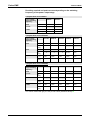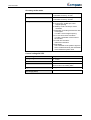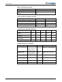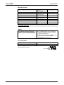
1
Electromechanical Automation
Compax3 Installation Manual
Single axis devices
Paper version
We reserve the right to make tecnical changes.
13.05.04 10:29
The data contained in this manual correspond to the current status at the time of printing.
192-120102 N8 Installation manual May 2004
Notes on the Documents Supplied
____________________________
Copyright © 2003 Parker Hannifin GmbH EME
All rights reserved.
Windows NT®, Windows 2000™, Windows XP™ are trademarks of Microsoft
Corporation.
EME - Electromechanical Automation Europe
C
R T I F I E
E
D
DIN EN ISO 9001
Q
U
Parker Hannifin GmbH
Electromechanical Automation
Postfach: 77607-1720
Robert-Bosch-Str. 22
D-77656 Offenburg
Tel.: +49 (0)781 509-0
Fax: +49 (0)781 509-98176
M
Germany:
A
L
T
IT Y
S
S Y
E
Reg. Nr. 36 38
E-mail: [email protected] mailto:[email protected]
Internet: www.parker-eme.com http://www.parker-eme.com
England:
Parker Hannifin plc
Electromechanical Automation
21 Balena Close
Poole, Dorset England, BH17 /DX UK
Tel.: +44 (0)1202 69 9000
Fax: +44 (0)1202 69 5750
E-mail: [email protected] mailto:[email protected]
Internet: www.parker-eme.com http://www.parker-eme.com
Italy:
Parker Hannifin S. p. A
Electromechanical Automation
Via Gounod 1
I-20092 Cinisello Balsamo (MI), Italy
Tel.: +39 (0)2660 12459
Fax: +39 (0)2660 12808
E-mail: [email protected] mailto:[email protected]
Internet: www.parker-eme.com http://www.parker-eme.com
EMN - Electromechanical Automation North America
USA:
Parker Hannifin Corporation
Electromechanical Automation
5500 Business Park Drive
Rohnert Park, CA 94928
Phone #: (800) 358-9068
FAX #: (707) 584-3715
E-mail: [email protected] mailto:[email protected]
Internet: www.compumotor.com http://www.compumotor.com
2
192-120102 N8 Installation manual May 2004
Notes on the Documents Supplied
Parker EME
1. Notes on the Documents
Supplied
Compax3 –
Installation manual
The present manual contains the installation instructions for the associated
Compax3 device series (refer to Chapter “Device Assignment”).
Compax3 CD
C3 ServoManager
The enclosed self-starting* CD contains the “C3 ServoManager” software tool for
configuring, optimizing etc. Compax3.
Please use always the latest C3 ServoManager version,
which can be found on the latest Compax3 CD enclosed.
Online help system
Manuals
The installation of ServoManager also copies an online help system to your PC that
can be started directly from ServoManager. You will find the complete description
of the selected device type in these online help files.
The CD also contains additional help files as well as manuals in PDF format that
can be printed to compile a complete hardcopy version of the respective manual.
Please note that the help files and the manuals are associated with defined device
and software versions.
Catalogs
Adobe Acrobat
Reader®
The catalogs supplied provide an overview of and information on the Compax3
device series.
The "Adobe Acrobat Reader®" is also included on the CD. It is free software that
lets you view and print "Adobe Portable Document Format" (PDF) files and it is
distributed and generally accepted throughout the world. You can also download it
directly from the Adobe website at: www.adobe.com/products/acrobat.
* If your PC has not been set up accordingly, start the "default.htm" file on the CD.
192-120102 N8 Installation manual May 2004
3
Notes on the Documents Supplied
1.1
C3 ServoManager
Installation of the C3
ServoManager
Minimum
requirements
The Compax3 ServoManager can be installed directly from the Compax3 CD.
Click on the appropriate hyperlink or start the installation program
"C3Mgr_Setup_V.... .exe" and follow the instructions.
For successful installation, your PC must meet the following minimum
requirements:
!
Windows NT 4.0 (Intel) with Service Pack 6, Windows 2000 (Service Pack 4
recommended) or Windows XP.
!
Administrator authorisation* on the system
!
Microsoft Internet Explorer 4.01 (SP2) or higher
!
Pentium-PC (300 MHz or faster is recommended)
!
64 MB RAM (128 MB recommended)
Required HD capacity
CD-Installation: 350 MB before installation, 200 MB after installation
! Super VGA-Monitor (with a resolution of at least 800 x 600, setting: small fonts)
!
!
Connection between
PC and Compax3
Your PC is connected with Compax3 over an RS232 cable (SSK1) (COM ½
interface on the PC based on X10 Compax3).
Start the Compax3 ServoManager and make the setting for the selected interface
in the menu Options: Port (RS232) COM 1 or COM 2.
Device selection
Configuration
4
In the menu tree under device selection you can read the device type of the
connected device (Online Device Identification) or select a device type (Device
Selection Wizard).
Then you can double click on "Configuration" to start the configuration wizard. The
wizard will lead you through all input windows of the configuration.
192-120102 N8 Installation manual May 2004
C3 ServoManager
Parker EME
General hazards
Contents
1. Notes on the Documents Supplied ........................................................3
1.1
C3 ServoManager..................................................................................... 4
2. Introduction .............................................................................................7
2.1
Device assignment .................................................................................. 7
2.2
Release - history - Compax3 ................................................................... 7
2.3
Type specification plate .......................................................................... 8
2.4
Safety Instructions................................................................................... 9
2.4.1.
2.4.2.
2.4.3.
General hazards ................................................................................................. 9
Safety-conscious working ................................................................................ 9
Special safety instructions ............................................................................. 10
2.5
Warranty conditions .............................................................................. 10
2.6
Conditions of utilization ........................................................................ 11
2.6.1.
2.6.2.
2.7
Conditions of utilization for CE-conform operation..................................... 11
Conditions of utilization for UL permission.................................................. 13
Manufacturer's Declaration of Conformity........................................... 14
3. Compax3 device description................................................................15
3.1
State of delivery ..................................................................................... 15
3.2
Plug and connector assignment Compax3.......................................... 16
3.2.1.
3.2.2.
3.2.3.
3.2.4.
3.2.5.
3.2.6.
3.2.7.
3.2.8.
3.2.9.
Function of the LEDs on the front panel ....................................................... 17
Power supply plug X1 for 230VAC devices................................................... 17
Power supply plug X1 for 400 VAC devices.................................................. 18
Ballast resistor / high voltage supply plug X2 for 230VAC devices ........... 18
Ballast resistor / high voltage supply plug X2 for 400VAC devices ........... 19
Motor / Motor brake (plug X3)......................................................................... 20
Control voltage 24VDC / enable (plug X4)..................................................... 21
RS232 / RS485 interface (plug X10) ............................................................... 22
Analog / Encoder (plug X11)........................................................................... 23
3.2.9.1 Wiring of analog outputs ....................................................................... 23
3.2.9.2 Wiring of the analog input ..................................................................... 23
3.2.10. Digital inputs/outputs (plug X12) ................................................................... 24
3.2.10.1 Output wiring of digital outputs.............................................................. 24
3.2.10.2 Input wiring of digital inputs................................................................... 25
3.2.11. Resolver / Feedback (connector X13)............................................................ 26
3.3
Installation and dimensions Compax3................................................. 27
3.3.1.
Installation and dimensions of Compax3 S0xx V2....................................... 27
192-120102 N8 Installation manual May 2004
5
Notes on the Documents Supplied
General hazards
3.3.2.
3.3.3.
3.3.4.
3.4
Installation and dimensions of Compax3 S038 and S075 V4...................... 28
Installation and dimensions of Compax3 S150 V4....................................... 29
Installation and dimensions of Compax3 S300 V4....................................... 30
Safety function – safe standstill - ......................................................... 31
3.4.1.
3.4.2.
Safety instructions for the “safe standstill” function .................................. 33
Application examples for “safe standstill” ................................................... 34
3.4.2.1 Sample circuit example of Compax3 devices without fieldbus
option .................................................................................................... 35
3.4.2.2 Sample circuit example of Compax3 devices with fieldbus option ....... 40
3.4.2.3 Sample circuit for C3 powerPLmC multi-axis application ..................... 44
4. Technical Data.......................................................................................48
5. Index.........................................................................................................1
6
192-120102 N8 Installation manual May 2004
Introduction
Parker EME
2. Introduction
In this chapter you can read about:
Device assignment ...........................................................................................................................7
Type specification plate ....................................................................................................................8
Release - history - Compax3 ............................................................................................................8
Safety Instructions ............................................................................................................................9
Warranty conditions........................................................................................................................10
Conditions of utilization...................................................................................................................11
Manufacturer's Declaration of Conformity .......................................................................................14
2.1
Device assignment
This manual applies to the following devices:
2.2
!
Compax3 S025 V2 + supplement
!
Compax3 S063 V2 + supplement
!
Compax3 S015 V4 + supplement
!
Compax3 S038 V4 + supplement
!
Compax3 S075 V4 + supplement
!
Compax3 S150 V4 + supplement
!
Compax3 S300 V4 + supplement
Release - history - Compax3
You will find the release overviews in the Internet
http://www.parker.com/euro_emd/DE/produkte/Compax3/release_info/de/index.htm
or on the Compax3 CD under "...\release_info\de\index.htm".
192-120102 N8 Installation manual May 2004
7
Introduction
2.3
Type specification plate
You will find the exact description of the device on the type specification
plate, which is located on the right side of the device:
Compax3 - Type
specification plate:
1
10
2
9
8
3
7
5
4
6
Explanation:
1
Type designation
The complete order designation of the device (2, 5, 6, 10, 9)
2
C3S025V2
C3: Abbreviation for Compax3
S: Single axis device with direct AC mains power supply
025: Device current drain in 100mA (025=2.5A)
V2: 230VAC (single phase); V4: 400VAC (three phase)
3
Unique number of the particular device
4
Nominal power supply voltage of the device
5
Designation of the feedback system
F10: Resolver
F11: SinCos© / Single- or Multiturn
F12: Feedback module for direct drives
6
Device interface
I10: Analog, Step/Direction and Encoder Input
I11 / I12: Digital Inputs / Outputs and RS232 / RS485
I20: Profibus DP
I21: CANopen
7
Corresponding fuse protection
8
Date of factory test
9
Options
10
Technology function
T10: Servo Controller
T11: Positioning
T30: Motion control programmable according to IEC61131-3
T40: Electronic cam control
8
192-120102 N8 Installation manual May 2004
Introduction
Parker EME
2.4
Safety Instructions
In this chapter you can read about:
General hazards ...............................................................................................................................9
Safety-conscious working .................................................................................................................9
Special safety instructions ..............................................................................................................10
2.4.1.
General hazards
General Hazards on Non-Compliance with the Safety Instructions
The device described in this manual is designed in accordance with the latest
technology and is safe in operation. Nevertheless, the device can entail certain
hazards if used improperly or for purposes other than those explicitly intended.
Electronic, moving and rotating components can
!
constitute a hazard for body and life of the user, and
!
cause material damage
Usage in accordance with intended purpose
The device is designed for operation in electric power drive systems (VDE0160).
Motion sequences can be automated with this device. Several motion sequences
can be can combined by interconnecting several of these devices. Mutual
interlocking functions must be incorporated for this purpose.
2.4.2.
Safety-conscious working
This device may be operated only by qualified personnel.
Qualified personnel in the sense of these operating instructions consists of:
!
!
!
!
Persons who, by virtue to their training, experience and instruction, and their
knowledge of pertinent norms, specifications, accident prevention regulations and
operational relationships, have been authorized by the officer responsible for the
safety of the system to perform the required task and in the process are capable
of recognizing potential hazards and avoiding them (definition of technical
personnel according to VDE105 or IEC364),
Persons who have a knowledge of first-aid techniques and the local emergency
rescue services.
Persons who have read and will observe the safety instructions.
Those who have read and observe the manual or help (or the sections pertinent
to the work to be carried out).
This applies to all work relating to setting up, commissioning, configuring,
programming, modifying the conditions of utilization and operating modes, and to
maintenance work.
This manual and the help information must be available close to the device during
the performance of all tasks.
192-120102 N8 Installation manual May 2004
9
Introduction
2.4.3.
Special safety instructions
!
Check the correct association of the device and its documentation.
!
Never detach electrical connections while voltage is applied to them.
!
!
Make sure that the device is operated only when it is in perfect condition.
!
Implement and activate the stipulated safety functions and devices.
!
Operate the device only with the housing closed.
!
Ensure that motors and any linear drives present are mounted securely.
!
2.5
Safety devices must be provided to prevent human contact with moving or
rotating parts.
Check that all live terminals are secured against contact. Fatal voltage levels of to
750V occur.
Warranty conditions
!
!
!
!
!
The device must not be opened.
Do not make any modifications to the device, except for those described in the
manual.
Make connections to the inputs, outputs and interfaces only in the manner
described in the manual.
When installing the device, make sure the heat dissipator receives sufficient air.
Attach the devices according to the mounting instructions, using the provided
fixing holes. We cannot provide any guarantee for any other mounting methods.
Note on exchange of options
Compax3 options must be exchanged in the factory to ensure hardware and
software compatibility.
10
192-120102 N8 Installation manual May 2004
Introduction
Parker EME
2.6
Conditions of utilization
2.6.1.
Conditions of utilization for CE-conform operation
- Industry and trade The EC guidelines for electromagnetic compatibility 89/336/EEC and for electrical
operating devices for utilization within certain voltage limits 73/23/EEC are fulfilled
when the following boundary conditions are observed:
Operation of the devices only in the condition in which they were delivered,
i.e. with all housing panels.
Mains filter:
A mains filter is required in the mains input line if the motor cable exceeds a certain
length. Filtering can be provided centrally at the plant mains input or separately at
the mains input to each device.
Commercial and residential area (limit values of Class A in accordance with
EN 61800-3)
The following mains filters are available for independent utilization:
Device: Compax3
Order No.:
Condition:
S0xx V2:
NFI01/01
Only for motor lines longer than 10m
S038, S075, S150 V4:
NFI01/02
Only for motor lines longer than 10m
S300
NFI01/03
Only for motor lines longer than 10m
Industrial area (limit values in accordance with EN 61800-3)
Longer motor cable lengths are possible in industrial areas without a mains power
filter.
Connection length: connection between mains filter and device:
unshielded:
shielded:
Motor and Feedback
cable:
< 0.5m
< 5m (fully shielded on ground – e.g. ground of control cabinet)
Operation of the devices only with Parker motor and feedback cables (their
plugs contain a special full surface area screening).
The following cable lengths are permitted:
Motor cable
< 100 m (the cable should not be rolled up!)
A motor output filter is required for motor cables >20 m.
!
MDR01/04 (max. 6.3A rated motor current)
!
MDR01/01 (max. 16A rated motor current)
!
MDR01/02 (max. 30A rated motor current)
192-120102 N8 Installation manual May 2004
11
Introduction
Shielding connection of the motor cable
The motor cable should be fully screened and connected to the Compax3 housing.
We offer a special shield connecting terminal as accessory item.
Feedback cable
< 100 m
Motors:
Operation with standard motors.
Control:
Use only with aligned controller (to avoid control loop oscillation).
Grounding:
Connect the filter housing and the Compax3 (grounding screw on the underside) to
the cabinet frame, making sure that the contact area is adequate and that the
connection has low resistance and low inductance.
Never mount the filter housing and the device on paint-coated surfaces!
Cable installation:
Signal lines and power lines should be installed as far apart as possible.
Signal leads should never pass close to excessive sources of interference (motors,
transformers etc.).
Accessories:
Make sure to use only the accessories recommended by Parker
Connect all cable shields at both ends, ensuring large contact areas!
Warning:
12
This is a product in the restricted sales distribution class according to EN
61800-3. In a domestic area this product can cause radio frequency
disturbance, in which case the user may be required to implement
appropriate remedial measures.
192-120102 N8 Installation manual May 2004
Introduction
Parker EME
2.6.2.
Conditions of utilization for UL permission
UL certification
conform to UL:
!
according to UL508C
Certified
!
E-File_No.: E235 342
The UL certification is documented by a “UL“ logo on the device
(type specification plate).
“UL“ logo
Conditions of utilization
!
The devices are only to be installed in a degree of contamination 2 environment
(maximum).
!
The devices must be appropriately protected (e.g. by a switching cabinet).
!
The terminals are suitable for field wiring.
!
Tightening torque of the field wiring terminals ( green Phoenix plugs)
!
!
!
!
C3SxxxV2
0.57-0.79Nm
5 - 7Lb.in
!
C3SxxxV4 except C3S300V4
0.57-0.79Nm
5 - 7Lb.in
!
C3S300V4
1.25-1.7Nm
11 - 15Lb.in
Temperature rating of field installed conductors shall be at least 60°C Use
copper conductors only. Please use the cables described in the accessories
chapter; they do have a temperature rating of at least 60°C
Maximum ambient temperature: 45°C.
Suitable for use on a circuit capable of delivering not more than 5000 rms
symmetrical amperes and 400 volts maximum.
ATTENTION
Danger of electric shock.
Discharge time of the bus capacitator is 5 minutes.
!
The drive provides internal motor overload protection.
This must be set so that 200% of the nominal motor current are not exceeded.
Cable cross-sections
! Mains supply: corresponding to the recommended fuses (see on page 48)
! Motor cable: corresponding to the nominal output currents (see on page 48)
2
! Maximum cross-section limited by the terminals mm / AWG
2
! C3SxxxV2
2.5mm
AWG 12
!
!
C3SxxxV4 except C3S300V4
4.0mm2
AWG 10
!
C3S300V4
6.0mm
AWG 7
2
Circuit protection
In addition to the branch circuit protection, the devices have to be protected with
the supplementary protector S 261 L, manufactured by ABB.
! C3S025V2: ABB, nominal 400V 10A, 6kA
! C3S063V2: ABB, nominal 400V, 16A, 6kA
! C3S038V4: ABB, nominal 400V, 10A, 6kA
! C3S075V4: ABB, nominal 400V, 16A, 6kA
! C3S150V4: ABB, nominal 400V, 20A, 6kA
! C3S300V4: ABB, nominal 400V, 25A, 6kA
! C3S300V4: ABB, nominal 400V, 25A, 6kA
!
192-120102 N8 Installation manual May 2004
13
Introduction
2.7
Manufacturer's Declaration of Conformity
As defined by the EC Electromagnetic Compatibility (EMC) Directive
89/336/EEC and
the EC Directive relating to electrical equipment designed for use
within
certain voltage limits (Low Voltage Directive)
73/23/EEC
We (the manufacturer)
Parker Hannifin GmbH
hereby declare that the product(s) listed below:
Device type: intelligent servo drives
Model: Compax3
to which this declaration relates, including the product model placed on the market
by us, have been designed and manufactured in conformity with the essential
requirements of the Standards and other Normative Documents listed in the
following.
Applied harmonized Standards, especially:
Electromagnetic Compatibility
EN 61 800-3
EMC product standard for adjustable speed electrical
VDE 0160 part 100
power drive systems including special testing
procedures
Safety
EN 50 178/
VDE 0160
Electronic equipment for use in power installations.
Caution!
The present Manufacturer's Declaration of Conformity is valid only if the master
conditions for operation described in the "Conditions of Use" section have been
met.
In the case of non-conformity with these conditions or upon modification of the
product, the present declaration will become invalid.
14
192-120102 N8 Installation manual May 2004
Compax3 device description
Parker EME
3. Compax3 device description
In this chapter you can read about:
State of delivery..............................................................................................................................15
Plug and connector assignment Compax3......................................................................................16
Installation and dimensions Compax3.............................................................................................27
Safety function – safe standstill - ....................................................................................................31
3.1
State of delivery
Compax3 is delivered without configuration!
After switching on the 25VDC supply, the red LED is flashing while the green LED
is dark.
Please configure the device with the help of the Windows-Software “Compax3 –
ServoManager”!
192-120102 N8 Installation manual May 2004
15
Compax3 device description
3.2
Plug and connector assignment Compax3
In this chapter you can read about:
Function of the LEDs on the front panel..........................................................................................17
Power supply plug X1 for 230VAC devices .....................................................................................17
Power supply plug X1 for 400 VAC devices ....................................................................................18
Ballast resistor / high voltage supply plug X2 for 230VAC devices ..................................................18
Ballast resistor / high voltage supply plug X2 for 400VAC devices ..................................................19
Motor / Motor brake (plug X3) .........................................................................................................20
Control voltage 24VDC / enable (plug X4) ......................................................................................21
RS232 / RS485 interface (plug X10) ...............................................................................................22
Analog / Encoder (plug X11)...........................................................................................................23
Digital inputs/outputs (plug X12) .....................................................................................................24
Resolver / Feedback (connector X13).............................................................................................26
Connection assignment based on the example of Compax3 S025 V2:
X1
AC Versorgung
AC Supply
X10
RS232 / RS485
X2
Ballast / DC LS
Ballast / DC HV
X11
Analog/Encoder
Analogue/Encoder
X3
Motor / Bremse
Motor / Brake
X12
Ein-/Ausgänge
Inputs/Outputs
X4
24VDC / Freigabe
24VDC / Enable
X13
Geber
Feedback
Always switch devices off before wiring them!
Dangerous voltages are still present until 5 minutes after
switching off the power supply!
Caution!
When the control voltage is missing there is no indication whether or
not high voltage supply is available.
16
192-120102 N8 Installation manual May 2004
Compax3 device description
Parker EME
3.2.1.
Function of the LEDs on the front panel
State
LED red
LED green
Voltages missing
off
off
While booting
alternately flashing
No configuration present.
SinCos feedback not detected.
! IEC program not compatible with the
firmware.
! For F12: Hall signals invalid.
flashing
off
Axis without current excitation
off
Flashes slowly
Power supplied to axis; commutation calibration
running
off
Flashes quickly
Axis with current excitation
off
on
Axis in fault status / fault present
on
off
!
!
3.2.2.
Power supply plug X1 for 230VAC devices
PIN
Description
1
L
2
N
3
PE
Mains connection: Compax3 S0xx V2
Controller type
S025 V2
S063 V2
Mains voltage
Single phase 230VAC + 10%
80-230VAC+10% / 50-60Hz
Rated input current
6Aeff
Maximum fuse rating per device
10A (automatic circuit 16A (automatic circuit
breaker D)
breaker D)
16Aeff
Always switch devices off before wiring them!
Dangerous voltages are still present until 5 minutes after
switching off the power supply!
192-120102 N8 Installation manual May 2004
17
Compax3 device description
3.2.3.
Power supply plug X1 for 400 VAC devices
PIN
Description
1
L1
2
L2
3
L3
4
PE
Mains connection Compax3 Sxxx V4
Controller type
S015 V4
Mains voltage
Three-phase 3*400VAC
80-480 VAC+10% / 50-60 Hz
Rated input current
3Aeff
Maximum fuse rating per 6A
device
S038 V4
S075 V4
6Aeff
10 Aeff
10A
16A
S150 V4
S300 V4
16Aeff
22Aeff
25A
Automatic circuit breaker D
Always switch devices off before wiring them!
Dangerous voltages are still present until 5 minutes after
switching off the power supply!
3.2.4.
Ballast resistor / high voltage supply plug X2 for 230VAC
devices
PIN
Description
1
+ Ballast resistor
2
- Ballast resistor
3
PE
4
+ DC high voltage supply
5
- DC high voltage supply
Caution! The connector assignment of X2 is changed!
Please note the screen printing on the front plate of the
device: this is valid
Brake operation Compax3 Sxxx V2
Controller type
S025 V2
S063 V2
Capacitance / storable energy
560µF / 15Ws
1120µF /30Ws
Minimum ballast - resistance
100Ω
56Ω
Recommended nominal power rating
20 ... 60W
60 ... 180W
Pulse power rating for 1s
1kW
2.5kW
Caution!
The power voltage DC of two Compax3 V2 devices (230V devices) must not
be connected.
18
192-120102 N8 Installation manual May 2004
Compax3 device description
Parker EME
3.2.5.
Ballast resistor / high voltage supply plug X2 for 400VAC
devices
PIN
Description
1
+ Ballast resistor
2
- Ballast resistor
3
PE
4
+ DC high voltage supply
5
- DC high voltage supply
Compax3 Sxxx V4 brake operation
Controller type
S015V4
S038V4
S075V4
S150V4
S300V4
Capacitance / storable
energy
235µF /
37Ws
235µF /
37Ws
470µF /
75Ws
690µF /
110Ws
1100µF /
176Ws
Minimum ballast resistance
100Ω
100Ω
56Ω
22Ω
15Ω
Recommended nominal
power rating
60 ...
100W
60 ...
250W
60 ... 500
W
60 ... 1000
W
60 ... 1000
W
Pulse power rating for 1s
1kW
2.5kW
5kW
10 kW
42kW
Connection of the power voltage of 2 Compax3 V4 devices (400V
devices)
In order to improve the conditions during brake operation, the DC power voltage of
2 devices may be connected.
The capacity as well as the storable energy are increased; furthermore the braking
energy of one device may be utilized by a second device, depending on the
application.
Please connect as follows:
Device 1 X2/4 to device 2 X2/4
Device 1 X2/5 to device 2 X2/5
Please note the following:
Caution! In case of non-compliance with the following instructions, the
device may be destroyed!
!
!
You can only connect two similar devices (same power supply; same rated
currents)
Connected devices must always be fed separately via the AC power supply.
192-120102 N8 Installation manual May 2004
19
Compax3 device description
3.2.6.
Motor / Motor brake (plug X3)
PIN
Description
1
U (motor)
2
V (motor)
3
W (motor)
4
PE (motor)
5
BR+
Motor holding brake
6
BR-
Motor holding brake
Shielding connection of the motor cable
The motor cable should be fully screened and connected to the Compax3 housing.
We offer a special shield connecting terminal as accessory item.
Connect the brake only on motors which have a holding
brake! Otherwise make no brake connections at all.
Motor holding brake output
20
Controller type
Compax3
Voltage range
21 – 27VDC
Maximum output current (short circuit
proof)
1.6 A
192-120102 N8 Installation manual May 2004
Compax3 device description
Parker EME
3.2.7.
Control voltage 24VDC / enable (plug X4)
PIN
Description
1
+24 V
2
Gnd24 V
3
Enable_in
4
Enable_out_a
5
Enable_out_b
Control voltage 24 VDC
Controller type
Compax3
Voltage range
21 - 27VDC
Current drain of the device
0.8 A
Total current drain
0.8 A + Total load of the digital outputs +
current for the motor holding brake
Ripple
0.5Vpp
Requirement according to safe extra
low voltage (SELV)
yes
Power stage enable: X4/3=24 VDC
Tolerance range: 18.0 V – 33.6 V / 720 Ω
The +24V supply can be taken, for example, from Pin 1.
Safe standstill (X4/3=0V)
For implementation of the "Safe standstill" safety feature in accordance with the
“protection against unexpected start-up“ described in EN1037. Please note also the
respective chapter (see on page 31 ) (see in the paper version “Installation manual
Compax3) with the circuit examples!
The energy supply to the drive is reliably shut off, the motor has no torque.
A relay contact is located between X4/4 and X4/5 (normally closed contact)
Enable_out_a - Enable_out_b
Power output
stage is
Contact opened
activated
Contact closed
deactivated
Series connection of these contacts permits certain determination of whether all
drives are de-energized.
Relay contact data:
Switching voltage (AC/DC): 100 mV – 60 V
Switching current: 10 mA – 0.3 A
192-120102 N8 Installation manual May 2004
21
Compax3 device description
3.2.8.
RS232 / RS485 interface (plug X10)
Interface selectable by contact functions assignment of X10/1:
X10/1=0V RS232
X10/1=5V RS485
RS232
PIN
X10
RS232 (Sub D)
1
2
3
4
5
6
7
8
9
(Enable RS232) 0V
RxD
TxD
DTR
GND
DSR
RTS
CTS
+5V
RS485 2-wire
PIN
X10
RS485 two wire (Sub D)
Pin 1 and 9 jumpered externally
1
2
3
4
5
6
7
8
9
Enable RS485 (+5V)
res.
TxD_RxD/
res.
GND
res.
TxD_RxD
res.
+5V
RS485 4-wire
22
PIN
X10
RS485 four wire (Sub D)
Pin 1 and 9 jumpered externally
1
2
3
4
5
6
7
8
9
Enable RS485 (+5V)
RxD
TxD/
res.
GND
res.
TxD
RxD/
+5V
192-120102 N8 Installation manual May 2004
Compax3 device description
Parker EME
3.2.9.
Analog / Encoder (plug X11)
PIN X11 Reference
High Density Sub D
1
2
3
4
5
6
7
8
9
10
11
12
13
14
15
+24V (output for encoder) max. 70mA
Ain1 -: analogue input - (14-bit)
D/A monitor channel 1 (±10V, 8-bit resolution)
D/A monitor channel 0 (±10V, 8-bit resolution)
+5V (output for encoder) max. 150mA
- Input: steps RS422 (5V - level)
+ Input: steps RS422 (5V - level)
+ Input: direction RS422 (5V - level)
Ain0 +: analogue input + (14-bit)
Ain1 +: analogue input + (14-bit)
Ain0 -: analogue input - (14-bit)
- Input: direction RS422 (5V - level)
Reserved
Reserved
GND
A/ (Encoder- input / -simulation)
A (Encoder- input / -simulation)
B (Encoder- input / -simulation)
B/ (Encoder- input / -simulation)
N/ (Encoder simulation)
N (Encoder simulation)
The exact assignment depends on the device type!
«
You will find the description of the device-specific assignment in the online help
which can be opened from the Compax3 – ServoManager.
3.2.9.1
Wiring of analog outputs
X11/4
X11/3
332Ω
+/-10V/1mA
(max: 3mA)
X11/15
3.2.9.2
Wiring of the analog input
2.2KΩ
10nF
Ain+
Ain-
X11/9 10KΩ
10KΩ
X11/11
2.2KΩ
10nF
192-120102 N8 Installation manual May 2004
23
Compax3 device description
3.2.10. Digital inputs/outputs (plug X12)
PIN
Input/output
X12/
I/O /X12
High density/Sub D
1
O
+24VDC output (max. 400mA)
2
O0
Output 0 (max. 100mA)
O1
Output 1 (max. 100mA)
4
O2
Output 2 (max. 100mA)
5
O3
Output 3 (max. 100mA)
I0
Input 0
7
I1
Input 1
8
I2
Input 2
9
I3
Input 3
10
I4
Input 4
11
I
24V input for the digital outputs Pins 2 to 5
12
I5
Input 5
13
I6
Input 6
14
I7
Input 7
15
O
Gnd 24 V
3
6
All inputs and outputs have 24V level.
Maximum capacitive load on the outputs: 50 nF (max. 4 Compax3 inputs)
The exact assignment depends on the device type!
You will find the description of the device-specific assignment in the online help
which can be opened from the Compax3 – ServoManager.
3.2.10.1
Output wiring of digital outputs
24V
F1
X4/1
F2 X12/1
SPS/
PLC
X12/11
X12/2
18.2KΩ
0V X4/2
X12/15
The circuit example is valid for all digital outputs!
The outputs are short circuit proof; a short circuit generates an error.
F1: Delayed action fuse
F2: Quick action electronic fuse; can be reset by switching the 24VDC supply off
and on again.
24
192-120102 N8 Installation manual May 2004
Compax3 device description
Parker EME
3.2.10.2
Input wiring of digital inputs
SPS/PLC
X12/1
F1 X4/1 24V
F2
100KΩ
22KΩ
X12/6
22KΩ
22KΩ
10KΩ
X12/15
X4/2 0V
The circuit example is valid for all digital inputs!
F1: Delayed action fuse
F2: Quick action electronic fuse; can be reset by switching the 24VDC supply off
and on again.
192-120102 N8 Installation manual May 2004
25
Compax3 device description
3.2.11. Resolver / Feedback (connector X13)
PIN
X13
Feedback /X13
High Density /Sub D (dependent on the Feedback Module)
Resolver (F10)
SinCos (F11)
Direct drives (F12)
1
res.
res.
Sense -
2
res.
res.
Sense +
3
GND
GND
Hall1
4
REF-Resolver+
Vcc (+8V)
Vcc (+5V) (controlled on the encoder
side) max. 200mA load
5
+5V (for temperature sensor)
+5V (for temperature and hall
sensors)
6
res.
CLKfbk
Hall2
7
SIN-
SIN-
SIN- / A- (Encoder)
8
SIN+
SIN+
SIN+ / A+ (Encoder)
9
res.
CLKfbk/
Hall3
10
Tmot
Tmot
Tmot
11
COS-
COS-
COS- / B- (Encoder)
12
COS+
COS+
COS+ / B+ (Encoder)
13
res.
DATAfbk
N+
14
res.
DATAfbk/
N-
15
REF-Resolver-
GND (Vcc)
GND (Vcc)
Note on F12:
+5V (Pin 4) is measured and controlled directly at the end of the line via Sense –
and Sense +.
Maximum length of cable: 100m
Caution! Pin 4 and Pin 5 must under no circumstances be connected!
26
192-120102 N8 Installation manual May 2004
Compax3 device description
Parker EME
3.3
Installation and dimensions Compax3
In this chapter you can read about:
Installation and dimensions of Compax3 S0xx V2...........................................................................27
Installation and dimensions of Compax3 S038 and S075 V4 ..........................................................28
Installation and dimensions of Compax3 S150 V4 ..........................................................................29
Installation and dimensions of Compax3 S300 V4 ..........................................................................30
3.3.1.
Installation and dimensions of Compax3 S0xx V2
Mounting:
3 socket head screws M5
Mounting spacing:
Device separation 15 mm
192-120102 N8 Installation manual May 2004
27
Compax3 device description
3.3.2.
Installation and dimensions of Compax3 S038 and S075 V4
Mounting:
3 socket head screws M5
Mounting spacing:
Device separation 15 mm
259
248
267
279
40
65
Compax3 S015 V4:
84
Compax3 S038 V4:
100
Compax3 S075 V4:
115
80
28
192-120102 N8 Installation manual May 2004
7,5
Compax3 device description
Parker EME
3.3.3.
Installation and dimensions of Compax3 S150 V4
Mounting:
4 socket head screws M5
Mounting spacing:
259
248
267
279
Device separation 15 mm
80
158
192-120102 N8 Installation manual May 2004
39
29
Compax3 device description
3.3.4.
Installation and dimensions of Compax3 S300 V4
Mounting:
4 socket head screws M5
Mounting spacing:
Compax3 S300 V4 is force-ventilated via a fan integrated into the heat
dissipator!
30
192-120102 N8 Installation manual May 2004
412
400
80
175
6
380
391
Device separation 15 mm
Compax3 device description
Parker EME
3.4
Safety function – safe standstill Compax3 is equipped with the "Safe Standstill" safety feature.
The “protection against unexpected start-up“ described in EN1037 can be
implemented with this feature.
Principle:
To ensure safe protection against a motor starting up unexpectedly, the flow of
current to the motor and thus to the power output stage must be prevented.
This is accomplished for Compax3 with two measures independent of each other
(Channel 1 and 2), without disconnecting the drive from the power supply:
Channel 1:
Activation of the power output stage can be disabled in the Compax3 controller by
means of a digital input or with a fieldbus interface (depending on the Compax3
device type) (deactivation of the energize input).
Channel 2:
The power supply for optocouplers and drivers of power output stage signals is
disconnected by a safety relay activated by the "ENABLE" (X4/3) input and
equipped with force-directed contacts. This prevents control signals from being
transferred to the power output stage.
The „Safe Standstill“ safety function as defined by EN 954-1 Category 3
is only possible if both channels are used.
Circuit diagram illustrating working principle:
Controller
Feedback
Energise
Enable
X4/3
Feedback
power
supply
X4/4
X4/5
L1
L2
X1/1
X1/2
L3
X1/3
safety relay
Feedback
power
supply
controller
motor
192-120102 N8 Installation manual May 2004
31
Compax3 device description
Notes
!
!
In normal operation of Compax3, 24 V DC of power is supplied to the "Enable"
input (X4/3). The drive is then controlled by the digital inputs/outputs or the
fieldbus.
When used properly, the “Safe standstill“ safety function is only used when the
motor is at a standstill, since it is not capable of braking a motor or bringing it to a
standstill by itself.
The “Safe Standstill” safety function is implemented in the following
devices:
Compax3 technology function
Device power
!
I10T10
!
S025V2
!
I11T11
!
S063V2
!
IxxT30
!
S015V4
!
IxxT40
!
S038V4
!
I12T11
!
S075V4
!
I20T11
!
S150V4
!
I21T11
!
S300V4
!
C10T11
Compax3-specific Inputs and Outputs channel 1
The "Energize" input and the "Controller Feedback" output depend on the
Compax3 device type:
!
!
!
!
32
Compax3 I10 T10, I11 T11, C10T11: a permanently assigned digital input and
output (see in the application examples).
Compax3 I12 T11: a permanently assigned digital input and output (see in the
application examples), or realize the “energize” function via the RS485 – bus
interface (programmable in the Compax3).
Compax3 T30, T40: "Energize" and "Controller Feedback" are applied to the I/Os
by way of the IEC program.
Compax3 with Bus: "Energize" and "Controller Feedback" are activated resp.
queried via the fieldbus (via control and status word).
192-120102 N8 Installation manual May 2004
Compax3 device description
Parker EME
3.4.1.
Safety instructions for the “safe standstill” function
!
!
!
!
!
!
!
!
!
!
!
Safety functions must be tested 100%.
Only qualified staff members are permitted to install the „Safe Standstill“ feature
and place it in service.
For all applications in which the first channel of the „Safe Standstill“ is
implemented by means of a PLC, care must be taken that the part of the program
that is responsible for current flowing to or not flowing to the drive is programmed
with the greatest possible care. The „Safe Standstill“ application example of
Compax3 with fieldbus should be considered.
The designer and operator responsible for the system and machine must refer
programmers who are involved to these safety-related points.
Terminal X4/2 (GND 24 V and at the same time the reference point for the safety
relay bobbin) must be connected with the PE protective lead. This is the only way
to ensure protection against incorrect operation through earth faults (EN60204-1
Section 9.4.3)!
All conditions necessary for CE-conform operation (see on page 11) must be
observed.
It should be noted in connection with the „Safe Standstill“ application example
illustrated here that after the Emergency Power-off switch has been activated, no
galvanic isolation in accordance with EN 60204-1 Section 5.5 is guaranteed. This
means that the entire system must be disconnected from the mains power supply
with an additional main switch or mains power contactor for an “Emergency
Power-off" (for example for repair jobs). Please note in this regard that even after
the power is disconnected, dangerous electrical voltages may still be present in
the Compax3 drive for about 5 minutes.
When using an external Emergency Stop module with adjustable delay time, (as
illustrated in the „Safe Standstill“ application example), it must be ensured that
the delay time cannot be adjusted by persons not authorized to do so (for
example by applying a lead seal).
The adjustable delay time on the Emergency Power-off module must be set to a
value greater than the duration of the braking ramp controlled by the Compax3
with maximum load and maximum speed.
If the setting range for the specified Emergency power-off module is not sufficient,
the Emergency power-off module must be replaced by another comparable
module.
All safety-related external leads (for example the control lead for the safety relay
and feedback contact) must absolutely be laid so they are protected, for example
in a cable duct. Short circuits and crossed wires must be reliably excluded!
If there are external forces operating on the drive axes, additional measures are
required (for example additional brakes). Please note in particular the effects of
gravity on suspended loads!
If the power fails, the possibility must be considered that for the application with
stop category K1, such as is described in the application example, it will no longer
be possible to execute the braking ramp controlled to speed 0.
It is important to note that if the drive is being activated (Energize) by the RS232
(RS485) interface, it may not be possible to execute switch-off by a controlled
braking ramp. For example, this is true when the set-up window of the C3
ServoManager is used. If set-up mode is turned on, the digital I/O interface and
fieldbus interface are automatically disabled.
192-120102 N8 Installation manual May 2004
33
Compax3 device description
3.4.2.
Application examples for “safe standstill”
In this chapter you can read about:
Sample circuit example of Compax3 devices without fieldbus option ..............................................35
Sample circuit example of Compax3 devices with fieldbus option ...................................................40
Sample circuit for C3 powerPLmC multi-axis application ................................................................44
The application examples described here correspond to Stop Category 1 as
defined by EN60204-1.
A Stop Category 0 in accordance with EN 60204-1 can be implemented, for
example by setting the delay time on the Emergency power-off switch to 0. The
Compax3 drive will then be turned off immediately in 2 channels and will not be
able to generate any more torque. Please take into consideration that the motor will
not brake and a coasting down of the motor may result in hazards. If this is the
case, a “Safe Standstill” in the stop category 0 is not permitted.
34
192-120102 N8 Installation manual May 2004
Compax3 device description
Parker EME
3.4.2.1
Sample circuit example of Compax3 devices without fieldbus
option
Sample circuit for the following Compax3 devices:
Compax3 I10 T10
!
Input "Energize": I0: X12/6
!
Output "Controller Feedback": O2: X12/4
The Stop Category 1 described here cannot be used in the „Torque
Controller“ operating mode.
At least Firmware Version V02.01.12 is required to be able to implement
the application described here for the Compax3 I10T10 device (the
Firmware Version of Compax3 can be seen with the C3 ServoManager
under "Online Device Identification").
Compax3 I12 T11:
!
Input "Energize": I2: X12/6
!
Output "Controller Feedback": O2: X12/4
or
!
The “Energize” function (channel 1) can be implemented via the RS485 bus
interface (X10) via a corresponding programming of the Compax3.
If, in this case, the motor current is to be disabled via channel 1, the Bit0 of the
DeviceControl (Control word_1) must be set to “LOW” via the RS485 bus
interface.
Compax3 I11 T11:
!
Input "Energize": I2: X12/8
!
Output "Controller Feedback": O2: X12/4
Compax3 Ixx T30 and Compax3 Ixx T40:
!
!
Input "Energize": apply the Enable Input of the MC_Power - module (IECprogram) to a Compax3 input.
Output "Controller Feedback": apply the Status output of the MC_Power module (IEC-program) to a Compax3 output.
If the Compax3 „Safe Standstill“ feature is required or used for a
system or machine, the two error messages „Motor_Stalled“ and
„Tracking“ must not be turned off for a programmable Compax3 drive
(T30, T40) with the „C3_Errormask“ function module.
192-120102 N8 Installation manual May 2004
35
Compax3 device description
Structure of Compax3 devices without fieldbus option:
!
!
!
36
2 Compax3 devices (the circuit example is also valid for one or multiple devices,
if it is adapted accordingly)
1 Emergency Power-off module (BH5928.47 manufactured by Dold)
1 Safety door monitor (BD5985N manufactured by Dold)
Note: With safety door monitor BD5985N, the safety door must be opened and
closed again every time after turning on the 24 V power supply so that the
Emergency power-off module can be acknowledged and reset. To avoid this,
safety door monitors with an additional simulation entry can also be used.
!
1 relay per Compax3
!
1 Emergency power-off switch
!
Hazardous area accessible via a safety door with safety door switch S1 and S2
!
3 buttons (S3, ... S5)
192-120102 N8 Installation manual May 2004
Compax3 device description
Parker EME
Gerät 1
L2
L1
S4
controller
I10T10:E0: X12/6
I11T11:E2: X12/8
Energise
Controller
Feedback
Feedback
power
supply
Kanal 1
Channel 1
A2: X12/4
K1
GND24V
safety
relay
X4/3
Enable
power
supply
X4/4
Feedback
X4/5
L1
X1/1
L2
X1/2
L3
X1/3
4
Gerät 2
motor
S5
controller
I10T10:E0: X12/6
I11T11:E2: X12/8
Feedback
power
supply
Energise
Controller
Feedback
4
motor
A2: X12/4
Schutztür offen
Safety door open
K2
GND24V
S1
Gefahrenbereich
Danger Zone
safety
relay
X4/3
S2
Enable
power
supply
X4/4
Feedback
X4/5
L1
X1/1
L2
X1/2
L3
X1/3
Kanal 2
Channel 2
L3
23
K1
S3
13
S31 S21
S11
K2
S33
S12
S34
S22
Not-Aus-Modul
Emergency power-off modul
BH5928.47(Dold)
Y39
Y40 A1(+)
58
S13
S23
S24
S14
2-kanaliger
Schutztürwächter
2-channel safety
door control
BD5985N(Dold)
24
57
13
14
+24V
14
Not-Aus-Schalter
Emergency
power-off switch
Y1
Y2
A2(-) A1(+)
GND24V +24V
S32
A2(-)
GND24V
Switches and buttons:
S1:
Closed when the safety door is closed
S2:
Closed when the safety door is closed
S3:
Activate Emergency power-off module
S4:
Guide Device 1 to a currentless state (error acknowledge)
S5:
Guide Device 2 to a currentless state (error acknowledge)
192-120102 N8 Installation manual May 2004
37
Compax3 device description
Basic functions:
Compax3 devices disabled by:
Channel 1: Energize – input to “0” through open contacts of Emergency Power-off
Module (13-14)
Channel 2: Enable input to "0" through open contacts of Emergency power-off
module (57 -58)
Activate Emergency power-off module
Before the Compax3 can be placed in operation, the Emergency power-off module
must be activated by a pulse to Input S33/S34.
Prerequisite:
!
!
S3 closed
Safety door closed: only in this case the safety door monitor enables the
emergency power off module via two channels.
K1 and K2 energized
! K1: receives current if Compax3 Device 1 is currentless (output = "1" in
currentless state) = Channel 1 feedback
! K2: receives current if compax3 device 2 is currentless (output = “1” in the
currentless state) = channel 1 feedback
! The feedback contact of all Compax3 devices must be closed (channel 2).
!
If S33 and S34 of the Emergency power-off module are briefly connected (pulse)
the contacts will be closed (between 13 and 14 and between 57 and 58)
Energize Compax3 (Motor and power output stage)
!
!
Compax3 devices are enabled by the Energize input and the Enable input via the
Emergency power-off module. (If a fault is still pending on Compax3, it must
previously be reset. The acknowledge/reset function depends on the type of the
Compax3 device).
The motors are energized with current.
Summary: Compax3 is only energized if the feedback functions are capable of
functioning via two channels.
Access to the hazardous area
Activate Emergency power-off switch
The two-channel interruption at the emergency power-off switch deactivates the
emergency power-off module – the contacts 13 – 14 will open immediately.
Channel 1: Compax3 devices receive the command via the Energize input to guide
the drive to a currentless state (using the ramp configured in the C3 ServoManager
for "drive disable").
Feedback channel 1: The Compax3 outputs “Controller Feedback” will energize
only the relays K1 and K2.
Channel 2: After the delay time set in the Emergency power-off module, (this time
must be set so that all drives are stopped after it has elapsed) the contacts
between 57 and 58 open, which in turn deactivates the Enable inputs of the
Compax3 devices.
Channel 2 feedback: Via the series circuit of all feedback contacts, the “Safe
Standstill” status (all Compax3 devices without current) is reported.
Only if the drives are all at a standstill, the safety door may be opened and the
hazardous area may be accessed.
38
192-120102 N8 Installation manual May 2004
Compax3 device description
Parker EME
If the safety door is opened during operation and the emergency-power-off switch
was not triggered before, the Compax3 drives will also trigger the stop ramp.
Caution! The drives may still move.
If danger to life and limb of a person entering cannot be excluded,
the machine must be protected by additional measures (e.g. a lock
on the door).
192-120102 N8 Installation manual May 2004
39
Compax3 device description
3.4.2.2
Sample circuit example of Compax3 devices with fieldbus
option
Sample circuit for the following Compax3 devices:
Compax3 I20 T11
Compax3 I20 T11
Layout:
!
!
!
40
2 Compax3 devices (the circuit example is also valid for one or multiple devices,
if it is adapted accordingly)
1 Emergency Power-off module (BH5928.47 manufactured by Dold)
1 Safety door monitor (BD5985N manufactured by Dold)
Note: With safety door monitor BD5985N, the safety door must be opened and
closed again every time after turning on the 24 V power supply so that the
Emergency power-off module can be acknowledged and reset. To avoid this,
safety door monitors with an additional simulation entry can also be used.
!
1 Relay (K1)
!
1 Emergency power-off switch
!
Hazardous area accessible via a safety door with safety door switch S1 and S2
!
1 button (S3)
192-120102 N8 Installation manual May 2004
Compax3 device description
Parker EME
Gerät 1
c h
ll e
Kanal 1
Channel 1
s te
Energise
Feedback
Fieldbus
power
Interface
supply
itt
s
S
n
Feldbus
Schnittstelle
K1
Controller
Feedback
ld b
rfa
ce
F ie
safety
relay
u
s
X4/3
Fieldbus
Interface
GND24V
te
controller
Feldbus
Schnittstelle
L1
bu
L2
F e ld
L3
In
Enable
SPS
PLC
power
supply
X4/4 Feedback
X4/5
L1
X1/1
L2
X1/2
L3
X1/3
Gerät 2
Energise
Feldbus
Schnittstelle
controller
Feedback
Fieldbus
power
Interface
supply
4
Controller
Feedback
4
safety
relay
X4/3
motor
motor
Schutztür offen
Safety door open
Enable
power
supply
S1
X4/4
Gefahrenbereich
Danger Zone
Feedback
S2
X4/5
L1
X1/1
L2
X1/2
L3
X1/3
23
13
S13
S23
S24
S14
2-kanaliger
Schutztürwächter
2-channel safety
door control
BD5985N(Dold)
Kanal 2
Channel 2
24
57
Y39
Y40 13
K1
S3
S31 S21
S11
S12
S33
Not-Aus-Schalter
Emergency
power-off switch
14
Y1
Y2
A2(-) A1(+)
GND24V +24V
S22
S34
S32
Not-Aus-Modul
Emergency power-off modul
BH5928.47(Dold)
58
+24V
A1(+)
14
A2(-)
GND24V
Switches and buttons:
S1:
Closed when the safety door is closed
S2:
Closed when the safety door is closed
S3:
Activate Emergency power-off module
192-120102 N8 Installation manual May 2004
41
Compax3 device description
Basic functions:
Compax3 devices disabled by:
Channel 1: Energize deactivated by PLC due to open contacts of the Emergency
power-off module (13 -14)
Channel 2: Enable input to "0" through open contacts of Emergency power-off
module (57 -58)
Activate Emergency power-off module
Before the Compax3 can be placed in operation, the Emergency Power-off module
must be activated by a pulse to Input S33/S34.
Prerequisite:
!
!
S3 closed
Safety door closed: only in this case the safety door monitor enables the
emergency power off module via two channels.
!
K1 energized via PLC
!
The feedback contact of all Compax3 devices must be closed (channel 2).
If S33 and S34 of the Emergency power-off module are briefly connected (pulse)
the contacts will be closed (between 13 and 14 and between 57 and 58).
Energize Compax3 (Motor and power output stage)
!
!
The PLC enables the Compax3 devices by means of the control word and the
Emergency power-off module enables the Compax3 devices by means of the
Enable input. (if a fault is still pending on Compax3, it must be previously
acknowledged/reset)
The motors are energized with current.
Summary: Compax3 is only energized if the feedback functions are capable of
functioning via two channels.
Access to the hazardous area
Activate Emergency power-off switch
The two-channel interruption at the emergency power-off switch deactivates the
emergency power-off module – the contacts 13 – 14 will open immediately.
The PLC evaluates this and responds as follows:
Channel 1: Compax3 devices receive the command via the control word 1to guide
the drive to a currentless state (using the ramp configured in the C3 ServoManager
for "drive disable").
Channel 1 feedback: The Compax3 feedback via the status word 2 is evaluated
by the PLC and passed on to the emergency power-off module via K1.
Channel 2: After the delay time set in the Emergency power-off module, (this time
must be set so that all drives are stopped after it has elapsed) the contacts
between 57 and 58 open, which in turn deactivates the Enable inputs of the
Compax3 devices.
Channel 2 feedback: Via the series circuit of all feedback contacts, the “Safe
Standstill” status (all Compax3 devices without current) is reported.
1
Example for the assignment of the control word (CW) to guide the drive to a stop and deenergize: Profibus: CW.2 = “0” (OFF3)
standstill via ramp (FSTOP3) and then switch to currentless. CANopen: CW.3 = “0” standstill via STOP ramp, then with CW.0
deenergize.
2
Example for the assignment of the status word (SW) to guide the drive to a standstill and switch: Profibus: SW.6 = “1” switch-on
disable (motor currentless). CANopen: SW.1 = “0” Ready to Switch on (motor deenergized).
42
192-120102 N8 Installation manual May 2004
Compax3 device description
Parker EME
Only if the drives are all at a standstill, the safety door may be opened and the
hazardous area may be accessed.
If the safety door is opened during operation and the emergency-power-off switch
was not triggered before, the Compax3 drives will also trigger the stop ramp.
Caution! The drives may still move.
If danger to life and limb of a person entering cannot be excluded,
the machine must be protected by additional measures (e.g. a lock
on the door).
192-120102 N8 Installation manual May 2004
43
Compax3 device description
3.4.2.3
Sample circuit for C3 powerPLmC multi-axis application
If the Compax3 “Safe Standstill” feature is required or used for a
system or machine, the two error messages “Motor_Stalled” and
“Tracking” must not be turned off with the “C3_Errormask” function
module.
Layout:
!
1 Compax3 with powerPLmC
!
n Compax3 devices
!
1 Emergency Power-off module (BH5928.47 manufactured by Dold)
!
44
1 Safety door monitor (BD5985N manufactured by Dold)
Note: With safety door monitor BD5985N, the safety door must be opened and
closed again every time after turning on the 24 V power supply so that the
Emergency power-off module can be acknowledged and reset. To avoid this,
safety door monitors with an additional simulation entry can also be used.
!
1 Relay (K1)
!
1 Emergency power-off switch
!
Hazardous area accessible via a safety door with safety door switch S1 and S2
!
1 button S3
192-120102 N8 Installation manual May 2004
Compax3 device description
Parker EME
C3_1 powerPLmC Program (Kanal 1; Channel 1)
C3_1 mit C3 powerPLmC
L2
L1
controller
Energise
Feedback
Controller
power
Feedback
supply
I0: X12/6
AND
Enable C3_1
O0: X12/2
Kanal 1
Channel 1
K1
C3_1
X4/3 Enable
power
supply
OR
Enable
GND24V
safety
relay
MC_POWER
C3_1.I0
Status
Axis
C3_1.O0
Error
AND
Enable C3_2
Feedback
MC_POWER
X4/4
X4/5
Feldbus
Schnittstelle
Fieldbus
Interface
X1
L1 /1
L2 /2
L3 /3
Enable
Enable C3_3
MC_POWER
Energise
Feedback
Controller
power
Feedback
supply
Enable
Enable C3_n
Enable
MC_POWER
X4/3
power
supply
Enable
X4/4 Feedback
C3_n
X4/5
Feldbus
Schnittstelle
Fieldbus
Interface
L2 /2
L3 /3
Error
AND
safety
relay
L1 /1
Status
Axis
C3_3
X1
Error
AND
C3_2
controller
Status
Axis
C3_2
Status
Axis
Error
C3_3
controller
motor 1
Energise
Feedback
Controller
power
Feedback
supply
motor 2
safety
relay
Enable
X4/3
power
supply
X4/4 Feedback
X4/5
Feldbus
Schnittstelle
Fieldbus
Interface
X1
L1 /1
L2 /2
L3 /3
C3_n
controller
Energise
Feedback
Controller
power
Feedback
supply
safety
relay
motor 3
Schutztür offen
Safety door open
Kanal 2
Channel 2
L3
motor n
S1
S2
Gefahrenbereich
Danger Zone
Enable
X4/3
power
supply
X4/4 Feedback
X1
L1 /1
L2 /2
L3 /3
23
13
X4/5
Feldbus
Schnittstelle
Fieldbus
Interface
S23
S24
S14
2-kanaliger
Schutztürwächter
2-channel safety
door control
BD5985N(Dold)
13
57
S31 S21
S11
K1
S3
S13
Not-Aus-Schalter
Emergency
power-off switch
24
S12
S33
14
Y1
Y2
A2(-) A1(+)
GND24V +24V
S22
S34
Y39 Y40
Not-Aus-Modul
Emergency power-off modul
BH5928.47(Dold)
58
+24V
A1(+)
S32
A2(-)
14
GND24V
Switches and buttons:
S1:
Closed when the safety door is closed
S2:
Closed when the safety door is closed
S3:
Activate Emergency power-off module
192-120102 N8 Installation manual May 2004
45
Compax3 device description
Basic functions:
Compax3 devices disabled by:
Channel 1: Energize input (I0) to C3_1 (with powerPLmC) to "0" through open
contacts of Emergency power-off module (13 -14)
Channel 2: Enable inputs of individual Compax3's to "0" through open contacts of
Emergency power-off module (57 -58)
Activate Emergency power-off module
Before the Compax3 can be placed in operation, the Emergency power-off module
must be activated by a pulse to Input S33/S34.
Prerequisite:
!
!
S3 closed
Safety door closed: only in this case the safety door monitor enables the
emergency power off module via two channels.
K1 energized
! K1: is energized if all Compax3 devices are currentless (Output O0 = “1”, if the
PC_POWER modules of all devices have the status “FALSE”. ) = Channel 1
feedback
! The feedback contact of all Compax3 devices must be closed (channel 2).
!
If S33 and S34 of the Emergency power-off module are briefly connected (pulse)
the contacts will be closed (between 13 and 14 and between 57 and 58)
Energize Compax3 (Motor and power output stage)
!
!
!
The Enable input is activated on all Compax3’s by the Emergency power-off
module.
Input I0 is also activated (="1") on Compax3 C3_1, which makes it possible to
activate the ENABLE inputs of the MC_Power modules with the AND modules. (If
a fault is still pending on Compax3, it must previously be reset. The
acknowledge/reset function depends on the type of the Compax3 device).
The motors are energized with current.
Summary: Compax3 is only energized if the feedback functions are capable of
functioning via two channels.
Access to the hazardous area
Activate Emergency power-off switch
The two-channel disconnecting at the emergency power-off switch deactivates the
emergency power-off module – the contacts 13 – 14 will open immediately.
Channel 1: The MC_POWER modules are deactivated for all Compax3's by Input
I0 = "0" on device C3_1 (with powerPLmC) via the AND modules. Compax3
devices are guided to a standstill and the current is switched off (by means of the
ramp for “drive disable) configured in the C3 ServoManager.
Channel 1 feedback: Output O0 = "1" if the MC_POWER components of all
devices have the status „FALSE“.
Channel 2: After the delay time set in the Emergency power-off module, (this time
must be set so that all drives are stopped after it has elapsed) the contacts
between 57 and 58 open, which in turn deactivates the Enable inputs of the
Compax3 devices.
Channel 2 feedback: Via the series circuit of all feedback contacts, the “Safe
Standstill” status (all Compax3 devices without current) is reported.
46
192-120102 N8 Installation manual May 2004
Compax3 device description
Parker EME
Only if the drives are all at a standstill, the safety door may be opened and the
hazardous area may be accessed.
If the safety door is opened during operation and the emergency-power-off switch
was not triggered before, the Compax3 drives will also trigger the stop ramp.
Caution! The drives may still move.
If danger to life and limb of a person entering cannot be excluded,
the machine must be protected by additional measures (e.g. a
safety door locking).
192-120102 N8 Installation manual May 2004
47
Technical Data
4. Technical Data
Mains connection: Compax3 S0xx V2
Controller type
S025 V2
S063 V2
Mains voltage
Single phase 230VAC + 10%
80-230VAC+10% / 50-60Hz
Rated input current
6Aeff
Maximum fuse rating per device
10A (automatic circuit 16A (automatic circuit
breaker D)
breaker D)
16Aeff
Mains connection Compax3 Sxxx V4
Controller type
S015 V4
S038 V4
Mains voltage
Three-phase 3*400VAC
S075 V4
S150 V4
S300 V4
16Aeff
22Aeff
80-480 VAC+10% / 50-60 Hz
Rated input current
3Aeff
Maximum fuse rating per 6A
device
6Aeff
10 Aeff
10A
16A
25A
Automatic circuit breaker D
Output data: Compax3 S0xx V2
Controller type
S025 V2
S063 V2
Output voltage (at 1*230 V)
3x 0-230V
3x 0-230V
Rated output current (at 1*230 V)
2.5Aeff
6.3Aeff
Pulse current
5,5Aeff for 5s
12.6Aeff for 5s
Power [hp]
1kVA
2.5kVA
Switching frequency
8kHz
8kHz
Power loss for In [Pv]
30W
60W
Efficiency
95%
96%
The currents are valid for the standard power output stage clock frequency of
8kHz.
Output data Compax3 Sxxd V4
48
Controller type
S015 V4
Output voltage (at 3*400
VAC)
S038 V4
S075 V4
S150 V4
S300 V4
3x 0-400V
Rated output current (at
3*400 VAC)
1.5Aeff
3.8Aeff
7.5Aeff
15Aeff
30Aeff
Pulse current for 5s
(at 400VAC)
4.5Aeff
9.0Aeff
15Aeff
30Aeff
60Aeff
Power [Ps]
(at 400VAC)
1kVA
2.5kVA
5kVA
10kVA
20kVA
Switching frequency
8kHz
8kHz
8kHz
4kHz
4kHz
Power loss for In
60W
80 W
120W
160W
350W
Efficiency
94%
94%
95%
97%
97%
192-120102 N8 Installation manual May 2004
Technical Data
Parker EME
Resulting nominal and peak currents depending on the switching
frequency of the power output stage
Compax3 S0xx V2 at 230VAV
Power output
stage switching
frequency
S025 V2
S063 V2
8kHz
Inominal
2.5Aeff
6.3Aeff
pre-set
Ipeak (<5s)
5.5Aeff
12.6Aeff
16kHz
Inominal
2.5Aeff
5.5Aeff
Ipeak (<5s)
5.5Aeff
12.6Aeff
Compax3 S0xx V4 at 3*400VAC
Power output
stage switching
frequency
4kHz
8kHz
16kHz
S015 V4
S038 V4
S075 V4
S150 V4
S300 V4
Inominal
-
-
-
15Aeff
30Aeff
Ipeak
(<5s)
-
-
-
30Aeff
60Aeff
Inominal
1.5Aeff
3.8Aeff
7.5Aeff
10.0Aeff
26Aeff
Ipeak
(<5s)
4.5Aeff
9.0Aeff
15.0Aeff
20.0Aeff
52Aeff
Inominal
1.5Aeff
2.5Aeff
3.7Aeff
5.0Aeff
14Aeff
Ipeak
(<5s)
3.0Aeff
5.0Aeff
10.0Aeff
10.0Aeff
28Aeff
S015 V4
S038 V4
S075 V4
S150 V4
S300 V4
Compax3 S0xx V4 at 3*480VAC
Power output
stage switching
frequency
4kHz
Inominal
-
-
-
13.9Aeff
30Aeff
pre-set
Ipeak
(<5s)
-
-
-
30Aeff
60Aeff
8kHz
Inominal
1.5Aeff
3.8Aeff
6.5Aeff
8.0Aeff
21.5Aeff
Ipeak
(<5s)
4.5Aeff
7.5Aeff
15.0Aeff
16.0Aeff
43Aeff
Inominal
1.0Aeff
2.0Aeff
2.7Aeff
3.5Aeff
10Aeff
Ipeak
(<5s)
2.0Aeff
4.0Aeff
8.0Aeff
7.0Aeff
20Aeff
16kHz
The values marked with gray are the pre-set values (standard values)!
192-120102 N8 Installation manual May 2004
«
49
Technical Data
Accuracy at the motor
Position resolution: 16 bits (= 0.005°)
Absolute accuracy: ±0.167°
! Position resolution: 19 bits (= 0.0002°)
! Absolute accuracy: ±0.005°
! Maximum position resolution
! Linear motor: 24 Bits per motor
magnet spacing
! Rotatory motor: 24 bits per motor
revolution
! Resolution for analog hall sensors with
1Vss signal:
13.5 bits / motor magnet spacing
! For 1Vss sine-cosine encoders:
13.5 bits / graduation of the scale of
the encoder
! For RS 422 encoders:
4xEncoder resolution
! Exactitude:
The exactitude of the position signal is
above all determined by the exactitude
of the feedback system used.
For option F10: Resolver
!
!
For option F11: SinCos
For option F12: Direct drives
Control voltage 24 VDC
50
Controller type
Compax3
Voltage range
21 - 27VDC
Current drain of the device
0.8 A
Total current drain
0.8 A + Total load of the digital outputs +
current for the motor holding brake
Ripple
0.5Vpp
Requirement according to safe extra
low voltage (SELV)
yes
192-120102 N8 Installation manual May 2004
Technical Data
Parker EME
Motors and feedback systems supported
Motors
!
Direct drives
!
Linear motors
!
Torque motors
Position encoder (Feedback)
Sinusoidal commutated synchronous
motors up to maximum rotation speed of
9000 rpm.
!
3 phase synchronous direct drives
!
Maximum rotating field frequency 600Hz
Option F10: Resolver
Litton:
!
JSSBH-15-E-5
!
JSSBH-21-P4
!
RE-21-1-A05
!
RE-15-1-B04
Tamagawa:
!
2018N321 E64
Siemens:
!
23401-T2509-C202
Option F11: SinCos©
!
!
Special encoder systems for direct
drives
Analog hall
sensors
Encoder
(linear or rotatory)
Singleturn (Stegmann)
Multiturn (Stegmann) Absolute position up
to 4096 motor revolutions.
Option F12
Sine - cosine signal (max. 5Vss3; typical
1Vss) 90° offset
4
! U-V Signal (max. 5Vss ; typical 1Vss)
120° offset.
5
! Sine-cosine (max. 5Vss ; typical 1Vss)
(max. 400kHz) or
! TTL (RS422) (max. 5MHz)
with the following modes of commutation:
!
!
Automatic commutation or
Digital hall sensors
! Distance coding with 1VSS - Interface
! Distance coding with RS422 - Interface
(Encoder)
!
Distance coded
feedback systems
Interfaces
Interface selection by external plug contact assignment
RS232
RS485 (2 or 4-wire)
!
115200 baud
!
Word length: 8 bits, 1 start bit, 1 stop bit
!
Hardware handshake XON, XOFF
!
9600, 19200, 38400, 57600 or 115200
baud
!
Word length 7/8 bit, 1 start bit, 1 stop bit
!
Parity (can be switched off) even/odd
!
2 or 4-wire
3
Max. differential input between SIN- (X13/7) and SIN+ (X13/8).
Max. differential input between SIN- (X13/7) and SIN+ (X13/8).
5
Max. differential input between SIN- (X13/7) and SIN+ (X13/8).
4
192-120102 N8 Installation manual May 2004
51
Technical Data
Motor holding brake output
Controller type
Compax3
Voltage range
21 – 27VDC
Maximum output current (short circuit
proof)
1.6 A
Brake operation Compax3 Sxxx V2
Controller type
S025 V2
S063 V2
Capacitance / storable energy
560µF / 15Ws
1120µF /30Ws
Minimum ballast - resistance
100Ω
56Ω
Recommended nominal power rating
20 ... 60W
60 ... 180W
Pulse power rating for 1s
1kW
2.5kW
Compax3 Sxxx V4 brake operation
Controller type
S015V4
S038V4
S075V4
S150V4
S300V4
Capacitance / storable
energy
235µF /
37Ws
235µF /
37Ws
470µF /
75Ws
690µF /
110Ws
1100µF /
176Ws
Minimum ballast resistance
100Ω
100Ω
56Ω
22Ω
15Ω
Recommended nominal
power rating
60 ...
100W
60 ...
250W
60 ... 500
W
60 ... 1000
W
60 ... 1000
W
Pulse power rating for 1s
1kW
2.5kW
5kW
10 kW
42kW
Ballast resistors for Compax3
Ballast resistor
Device
sustained
dynamic
BRM8/01 (100Ω
Ω)
Compax3 S025 V2
60W
250W (<1s; ≥10s cooling time)
180W
2300W (<0.4s; ≥8s cooling
time)
Compax3 S015 V4
Compax3 S038 V4
BRM5/01 (56Ω
Ω)
Compax3 S063 V2
Compax3 S075 V4
52
BRM6/02 (33Ω
Ω)
Compax3 S150 V4
570W
6900 W (<1s; ≥ 20s cooling
time)
BRM4/01 (15Ω
Ω)
Compax3 S300 V4
570W
6900 W (<1s; ≥ 20s cooling
time)
BRM4/02 (15Ω
Ω)
Compax3 S300 V4
740W
8900W (<1s; ≥20s cooling time)
BRM4/03 (15Ω
Ω)
Compax3 S300 V4
1500W
18kW (<1s; ≥20s cooling time)
192-120102 N8 Installation manual May 2004
Technical Data
Parker EME
Mechanical data
Controller type
Dimensions
Weight [kg]
HxWxD [mm]
Compax3 S025 V2
199 x 84 x 172
2.0
Compax3 S063 V2
199 x 100 x 172
2.5
Compax3 S015 V4
260 x 84 x 172
3.1
Compax3 S038 V4
260 x 100 x 172
3.5
Compax3 S075 V4
260 x 115 x 172
4.3
Compax3 S150 V4
260 x 160 x 172
6.8
Compax3 S300 V4
380 x 175 x 172
10.9
Protection type IP20
Safety
Safe standstill certified according to
EN954-1, category 3 (BG-PRÜFZERT)
For implementation of the “protection
against unexpected start-up“ function
described in EN1037.
! Please note the circuit examples in the
paper manual supplied. Circuit
examples (see on page 31).
!
UL certification
conform to UL:
!
according to UL508C
Certified
!
E-File_No.: E235 342
The UL certification is documented by a “UL“ logo on the device
(type specification plate).
“UL“ logo
192-120102 N8 Installation manual May 2004
53
Technical Data
Insulation requirements
Protection class
Protection class I according to EN 50 178 (VDE
0160 part 1)
Protection against human contact with
dangerous voltages
According to DIN VDE 0106, part 100
Overvoltage category
Voltage class III according to HD 625 (VDE
0110-1)
Degree of contamination
Degree of contamination 2 according to HD 625
(VDE 0110 part 1) and EN 50 178 (VDE 0160
part 1)
Ambient conditions
General ambient conditions
In accordance with EN 60 721-3-1 to 3-3
Climate (temperature/humidity/barometric
pressure): Class 3K3
Permissible ambient temperature:
Operation
Storage
Transport
0 to +45 C
–25 to +70 C
–25 to +70 C
Class 3K3
Class 2K3
Class 2K3
Tolerated humidity:
No condensation
Operation
Storage
Transport
<= 85% Class 3K3
<= 95% Class 2K3
<= 95% Class 2K3
Elevation of operating site
<=1000m above sea level for 100% load
ratings
(Relative humidity)
Please inquire for greater elevations
Cooling mode
Compax3 S025 V2 ... S150 V4: convection
Compax3 S300 V4: force-ventilation via fan in
the heat dissipator
Sealing
IP20 protection class according to EN 60 529
EMC interference emission
Limit values according to EN 61 800-3, Class ‘A‘
with integrated mains filter for up to 10 m cable
length, otherwise with external mains filter
EMC disturbance immunity
Limit values for industrial utilization according to
EN 61 800-3 (includes EN 50 081-2 and EN 50
082-2)
EC directives and harmonised EC norms
EC low voltage directive
73/23/EEC and RL 93/68/EEC
EN 50 178, General industrial safety norm
Equipping electric power systems with
electronic operating equipment
HD 625, general electrical safety
Insulation principles for electrical operating
equipment
EN 60 204-1, Machinery norm, partly applied
EC-EMC directive
89/336/EEC
EN 61 800-3, EMC norm
Product standard for variable speed drives
EN 50 081-2 ... 50 082-2, EN 61 000-4-2 ...61
000-4-5
54
192-120102 N8 Installation manual May 2004
Index
Parker EME
5. Index
Output wiring of digital outputs • 24
A
P
Analog / Encoder (plug X11) • 23
B
Ballast resistor • 18, 52
Ballast resistor / high voltage supply plug X2 for
230VAC devices • 18
Ballast resistor / high voltage supply plug X2 for
400VAC devices • 19
C
C3 ServoManager • 4
Compax3 device description • 15
Conditions of utilization • 11
Conditions of utilization for CE-conform
operation • 11
Conditions of utilization for UL permission • 13
Control voltage 24 VDC • 21
Control voltage 24VDC / enable (plug X4) • 21
D
Device assignment • 7
Digital inputs/outputs (plug X12) • 24
F
Function of the LEDs on the front panel • 17
G
General hazards • 9
I
Input wiring of digital inputs • 25
Installation and dimensions Compax3 • 27
Installation and dimensions of Compax3 S038
and S075 V4 • 28
Installation and dimensions of Compax3 S0xx
V2 • 27
Installation and dimensions of Compax3 S150
V4 • 29
Installation and dimensions of Compax3 S300
V4 • 30
Introduction • 7
M
Manufacturer's Declaration of Conformity • 14
Motor / Motor brake (plug X3) • 20
Motor Connection • 20
Motor holding brake • 20
N
Notes on the Documents Supplied • 3
O
Plug and connector assignment Compax3 • 16
Plug assignment Compax3S0xx V2 • 16, 17, 18,
20, 21, 22, 26
Power supply • 16, 17
Power supply plug X1 for 230VAC devices • 17
Power supply plug X1 for 400 VAC devices • 18
R
Release - history - Compax3 • 7
Resolver • 26
Resolver / Feedback (connector X13) • 26
RS232 / RS485 interface (plug X10) • 22
RS232 plug assignment • 22
RS485 plug assignment • 22
S
Safe standstill • 31
Safe Standstill application example • 34
Safety function – safe standstill - • 31
Safety Instructions • 9
Safety notes on the Safe Stop feature • 33
Safety-conscious working • 9
Sample circuit example of Compax3 devices
with fieldbus option • 40
Sample circuit example of Compax3 devices
without fieldbus option • 35
Sample circuit for C3 powerPLmC multi-axis
application • 44
Special safety instructions • 10
State of delivery • 15
T
Technical Data • 48
Type specification plate • 8
U
Usage in accordance with intended purpose • 9
W
Warranty conditions • 10
Wiring of analog outputs • 23
Wiring of the analog input • 23
X
X1 • 17
X10 • 22
X11 • 23
X12 • 24
X13 • 26
X2 • 18
X3 • 20
X4 • 21
192-120102 N8 Installation manual May 2004
1
Index
2
192-120102 N8 Installation manual May 2004