1
C3 ServoManager
Parker EME
General hazards
Contents
1. Notes on the Documents Supplied ........................................................3
1.1
C3 ServoManager..................................................................................... 4
2. Introduction .............................................................................................7
2.1
Device assignment .................................................................................. 7
2.2
Release - history - Compax3 ................................................................... 7
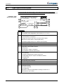
2.3
Type specification plate .......................................................................... 8
2.4
Safety Instructions................................................................................... 9
2.4.1.
2.4.2.
2.4.3.
General hazards ................................................................................................. 9
Safety-conscious working ................................................................................ 9
Special safety instructions ............................................................................. 10
2.5
Warranty conditions .............................................................................. 10
2.6
Conditions of utilization ........................................................................ 11
2.6.1.
2.6.2.
2.7
Conditions of utilization for CE-conform operation..................................... 11
Conditions of utilization for UL permission.................................................. 13
Manufacturer's Declaration of Conformity........................................... 14
3. Compax3 device description................................................................15
3.1
State of delivery ..................................................................................... 15
3.2
Plug and connector assignment Compax3.......................................... 16
3.2.1.
3.2.2.
3.2.3.
3.2.4.
3.2.5.
3.2.6.
3.2.7.
3.2.8.
3.2.9.
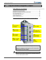
Function of the LEDs on the front panel ....................................................... 17
Power supply plug X1 for 230VAC devices................................................... 17
Power supply plug X1 for 400 VAC devices.................................................. 18
Ballast resistor / high voltage supply plug X2 for 230VAC devices ........... 18
Ballast resistor / high voltage supply plug X2 for 400VAC devices ........... 19
Motor / Motor brake (plug X3)......................................................................... 20
Control voltage 24VDC / enable (plug X4)..................................................... 21
RS232 / RS485 interface (plug X10) ............................................................... 22
Analog / Encoder (plug X11)........................................................................... 23
3.2.9.1 Wiring of analog outputs ....................................................................... 23
3.2.9.2 Wiring of the analog input ..................................................................... 23
3.2.10. Digital inputs/outputs (plug X12) ................................................................... 24
3.2.10.1 Output wiring of digital outputs.............................................................. 24
3.2.10.2 Input wiring of digital inputs................................................................... 25
3.2.11. Resolver / Feedback (connector X13)............................................................ 26
3.3
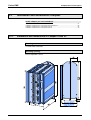
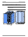
Installation and dimensions Compax3................................................. 27
3.3.1.
Installation and dimensions of Compax3 S0xx V2....................................... 27
192-120102 N8 Installation manual May 2004
5