1
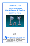
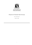
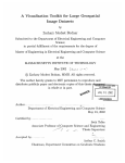
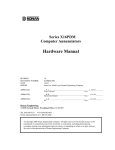
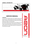
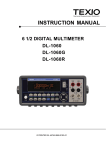
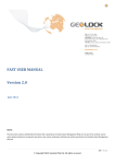
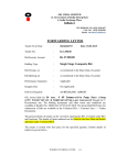
User Manual
(11) Display for the selected function
(12) Display for the unit of
measured quantity.
(13) Over range indication for
positive analog range.
(14) Pointer for analog indication.
(4) Pushbutton for manual range
(15) Scale for analog indication
selection
(16) Over range indication for
(5) Multi function pushbutton
negative analog range.
(17) Low battery indication.
(6) Function selector switch.
(18) Buzzer indication
(19) Display 0C for temperature
(7) Terminal sockets
measurement range.
(8) Symbol for ’’CONTINUOUSLY ON" (20) Rotary mechanism for clamp jaws.
(21) Safe trigger mechanism.
(9) Display for digits, decimal point and
polarity.
(10) Display for manual range selection,
data HOLD and MIN/MAX storage.
(1)
(2)
(3)
Liquid crystal display
ON/OFF pushbutton
Pushbutton for data hold
and MIN/MAX storage functions
Contents
1.
2.
Page
Introduction
............................................................................ 2
Safety features and safety precautions ........................................... 2
3.
Switching the Clampmeter "ON" ..................................................... 3
4.
Function and range selection .......................................................... 4
4.1 Autoranging
............................................................................ 4
4.2 Manual range selection ....................................................................4
5
Liquid crystal display ....................................................................... 5
5.1 Digital display
............................................................................ 5
5.2 Analog indication .............................................................................5
5.3 Backlit .............................................................................................5
6. Data
“HOLD” facility ..................................................................... 6
7.
Minimum value and maximum value "MIN/MAX storage facility. ........... 6
8.
Voltage measurement .....................................................................9
8.1 Voltage measurement on electrical system upto 1000V
with the KS30 measuring adapter .................................................. 9
9. Resistance measurement ...............................................................11
10. Diode test and continuity test ..........................................................11
11. Temperature measurement ........................................................... 12
12. Capcacitance measurement
........................................................ 12
13. Frequency measurement .............................................................13
14. Duty cycle measurement .................................................................13
15. AC Current measurement ..............................................................14
16. Empty Positions .......................................................................... 16
17. Specifications .................................................................................. 17
18. Maintainance ................................................................................21
18.1 Battery .........................................................................................21
18.2 Periodic Check-up : ....................................................................22
19. Servicing .......................................................................................22
1. Introduction:
Thank you very much for selecting
.
LUMEL S.A. is the leading manufacturer of Electrical and Electronics
state-of-art measuring instruments.
These clamp meters are manufactured as per IS 13875 and DIN 43751
I
2. Safety features and safety precautions
You have chosen a Clamp meter which provides you a very high degree
of safety. The digital clamp meter NC10 300A/1000A manufactured
and tested in compliance with the safety standard IEC 61010-1:2001 /
DIN EN 61010-1:2001. In case of incorrect use or careless handing,
the safety of both user and clamp meter is not assured.
For proper use and safe handling,it is absolutely necessary to read and
understand the operating instructions before using the clamp meter.
Please note the following safety precautions:
The clamp meter must be operated only by persons who understand
the danger of shock hazards and are aware of the necessary safety
precautions. Shock hazards exist wherever voltages of more than
30V (TRMS) are present.
Do not work alone in shock hazardous environment while carrying
out measurement.
The maximum permissible voltage between any of the terminal
sockets (7) and ground is 1000V.
Take into account that unexpected voltages can occur on device
under test (e.g. defective instrument). For example, capacitors may
be charged to a dangerously high voltage.
Verify that the test leads are in good condition, e.g.no cracked
insulation, no open circuits in the leads or connectors.
This clamp meter must not be used for measurements on circuits with
corona discharge (high voltage).
Be particularly careful when measuring on HF circuits. Dangerous
composite voltages may exist there.
Measurements under moist environmental conditions are not
permitted.
Do not overload the measuring ranges beyond their allowable
capacities. Limit values are given in specifications. Ref. Chapter 16.
For safe voltage measurements in power systems upto 1000V, we
recommend the KS30 measuring adapter, which is available as an
accessory. Its internal resistance limits the measuring current in the
case of overvoltage, in correct operation and safely suppresses
sparking from spark gap. Also refer to Section "8.1 Voltage
measurement on electrical systems up to 1000V with KS30
measuring adapter.
Meaning of categories and their significance per IEC 61010-1
CAT I: Measurements in electrical circuits which are not directly
connected to the mains: for example electrical systems in motor
vehicles and aircraft, batteries etc.
circuits
CAT II: Measurements in electrical which are electrically connected
to the low-voltage mains:with plugs, e.g. at home, in the office or
laboratory etc.
CAT III: Measurements in building installations, stationary power
consumers, distributor terminals, devices connected permanently
to the distributor
CAT IV: Measurements at power sources for low-voltage installations,
meters, mains terminals, primary over voltage protection devices.
Meaning of the symbols on the device
Warning of a danger point
(Attention, refer to the user
manual)
Earth (ground) terminal.
Double or reinforced insulation
CAT III / IV
Instrument for over voltage
category II/III OR IV
Meaning of the acoustic signals
1) Intermittent acoustic signal: Voltage limit exceeded; for Voltage>1000 V
2) Intermittent acoustic signal: Current limit exceeded; for Current>1100 A
Repair, replacement of parts:
When opening the meter, live parts may be exposed. Therefore, the
meter must be disconnected from the measuring circuit prior to opening
its case for repair or replacement of parts. If repair cannot be avoided
unless the meter is opened and live, this work must only be performed
by a qualified person who understands the danger involved.
Faults and abnormal stress:
When it is realised that the safe operation is no longer possible, take the
meter out of service and secure it against accidental use.
Safe operation may not be possible,
when the meter shows obvious signs of damage,
when the meter no longer functions correctly,
after prolonged storage under adverse conditions,
due to severe stress during transportation.
3. Switching the Clamp meter "ON"
Battery
We have already fitted your meter with a 9 V flat cell battery according to
IEC 6 F 22 or IEC 6 LR 61. It is ready for operation. Before you use the
meter for the first time or after storage, refer to Section "18.1 MaintenanceBattery".
Switching the meter "ON"
Press the "ON/OFF" pushbutton (2).
Switch-"ON" is acknowledged by a sound signal. As long as you
keep the pushbutton pressed, all segments of the liquid crystal display
(LCD) will appear. The LCD is shown behind cover page
After the pushbutton is released, the meter is ready for operation.
Note:
Electric discharges and high-frequency influence may cause incorrect
information to be displayed and block the measuring process. Reset the
meter by switching it OFF and ON again otherwise, check the battery
connections.
Disconnect the clamp meter from the measuring circuit before
you open it, and see section "18. Maintenance" !
Automatic TURN-OFF
The meter turns off automatically, when the measured value remains
constant (variations of the measured value < + 2digits) for about 10
minutes and when neither a pushbutton nor the function selector switch
is operated during that time.
How to prevent automatic TURN-OFF
In order to prevent automatic "TURN OFF" select "CONTINUOUSLY
ON" mode. For this, press yellow multi-function pushbutton (5) and the
"ON/OFF" pushbutton (2) together. The function "CONTINUOUSLY ON"
is shown on the LCD (1) by the symbol ON (8).
Turning the multimeter OFF
Press the "ON/OFF" pushbutton (2).
4. Function and range selection
4.1 Autoranging
The multimeters feature autoranging for all measuring ranges with the
exception of the 30 mV
, 300 mV
ranges. Autoranging is
Automatically selected after switching the multimeter ON. According
to the measured quantity applied, the multimeter automatically selects
the measuring range which gives the best resolution. When switching to
frequency measurement and ratio measurement the previously selected
voltage measuring range is maintained.
The meter switches automatically to :
the next higher range
at + (3099 digits + 1 digit)
the next lower range
at + (240/280 digits - 1 digit)
4.2 Manual range section
You can switch OFF autoranging and select the ranges manually
according to the table on the following page.
Manual mode is switched OFF when pushbutton AUTO/MAN is pressed
(4) for approximately 1s, when the function selector switch (6) is operated,
or when the meter is turned OFF and ON again.
When switching back to autoranging from 30 mV or 300 mV ranges,
3 V range is automatically selected.
F
30 nF 300 nF 3 μF 30 μ F 30 nF...
300 Hz 3 KHz 30 KHz 100 KHz 300 Hz...
300A 1000A 300A ...
NC10 1000A
A
30A
300A 30A ...
NC10 300A
A
Hz
.
.
5. Liquid crystal display
5.1 Digital display
The digital display (9) shows the measured value with correct location of decimal
point and sign. The selected measuring Unit (12) and the function (11)
are simultaneously displayed. When measuring DC quantities, a minus sign
appears in front of the digits, when the positive pole of the measured
quantity is applied to the " " input terminal. When upper range limit 3099
: 1999), is exceeded then "OL" is displayed.
( on the range
With V and measurements, the digital display is updated two times
per second.
A
A
5.2 Analog indication
The analog indication with pointer presentation gives the dynamic
response of a moving-coil movement and is updated 20 times per second,
when measuring Vand . Analog indication is of particular advantage
when observing variations of measured values and for calibration
procedures.
The analog indicator has its own polarity indication. When measuring
DC quantities, the analog scale (15) has a negative range of 4 scale
divisions so that variations of the measured values around "zero"can be
observed exactly. When the measured value exceeds the range of
indication, the left triangle (16) is shown before the polarity of the analog
indicator switches over after approximately 0.7s. The over range indication
on the measuring range (> 3099 digits, on the range
>1999) is shown
by the right triangle (13).
The instrument is provided with user selectable Back-lit for taking
measurements in poor lighting conditions / dark areas.
Switching the Backlit ON
by pressing "AUTO/MAN" and "HOLD" keys simultaneously
the Backlit can be switched ON.
Switching the Backlit OFF
by pressing "AUTO/MAN" and “HOLD" keys simultaneously
the Backlit can be switched OFF.
6. Data “HOLD” facility
The HOLD function allows to automatically hold the measured values.
The meter holds the measured value on the digital display with a sound
signal and displays “HOLD” on LCD display(10). The probes or clamp
can now be removed from the measuring point and the measured value
on the digital display (9) can be read. The analog indication is not influenced by the data HOLD.
The actual measured value can still be noted / read. Note that with
a held digital display, the location of the decimal point is also held.
With autoranging selected, the measuring range of the analog indicator
is no longer known.
Note: Hold function is not available in functions
ranges in function V .
0
, C and 30mV and 300 mV
To activate “HOLD” function momentarily press the HOLD key.
As long as the data HOLD function is active, manual range selection
is not possible. The data HOLD function is switched OFF, when,
The "HOLD” pushbutton (3) is pressed for approx. 1s. This is
acknowledged by 2 sound signals.
The function selector switch (6) is operated or
The multimeter is turned OFF and ON again.
7. Minimum value and Maximum value ’’MIN/MAX"
storage facility.
With the MIN/MAX function, you can hold the minimum and the maximum
measured value which was applied to the input of the multimeter after
activating MIN/MAX function. The most important application is the
determination of the minimum and the maximum value for long-term
monitoring of measured quantities. MIN/MAX does not influence the
analog indication The actual measured value can still be noted/read.
Apply the measured quantity to the meter and select the measuring
range prior to activating the MIN/MAX function.
With the function activated, you can select the measuring ranges only
manually, if you switch to another range, the stored MIN/MAX values are
cleared.
Function
MIN / MAX
MeasDATA
uring
MIN / MAX
ranges
(3)
Measured
Values
MIN and MAX
Meter acknowledgement
Display
Meas.
MIN Sound
Value
digital MAX Signal
1.
Activate and
Store
2 x Short,
30 mV/
300 mV
and 0C
1 x short
2.
Store and
display
short
3.
Return to 1.
Short
Same as 1.,
Same Stored Values are same
as 1.
as 1.
not cleared
Reset
Long
Cleared
short
actual
measured
value
stored
Storage Continued MIN
in the background, value
new MIN / MAX. stored
values are displayed MAX
value
Stored
MIN
and
MAX
flash
1x
MIN
1x
MAX
1x
same
as 1.
1x
Cleared Cleared
2x
The MIN/MAX function is switched OFF, when the MIN/MAX pushbutton
(3) is pressed for approximately 1s, or when the function selector switch
(6) is operated, or when the meter is turned OFF and ON again.
Voltage measurement
Voltage measurement on electrical systems up to 1000 V
with the KS30 measuring adapter
8. Voltage measurement
According to the voltage to be measured , set the function selector
V
switch (6) to V
Connect the test leads as shown. The ’’
’’ socket should be
connected to the lowest potential ground available.
~,
Notes :
The 30 mV and 300 mV
measuring ranges can only be selected
manually with the ’’ AUTO/MAN ’’ pushbutton (4) !
On the 1000 V range, an intermittent sound signal warns you, when the
measured value exceeds the upper range limit.
Zero adjustment on the 30 mV
measuring range
Connect the test leads to the meter and join the free ends.
After having selected the measuring range, briefly press the yellow multifunction pushbutton (5).
The meter acknowledges zero setting by a sound signal, the LCD shows
’’00.00’’ (+ 1 digit) and the decimal point flashes. The displayed voltage
at the instant the pushbutton is pressed, is used as reference value
(max + 200 digits) it is automatically deducted from the values measured
thereafter.
The zero adjustment is cleared when ;
By pressing the yellow multifunction pushbutton (5) for a long time,
clearance is acknowledged by the two sound signal.
By switching the instrument OFF.
8.1 Voltage measurement on electrical systems up to
1000V with the KS30 measuring adapter.
On low-Voltage systems, transient overvoltages of several kilovolts can
occur due to switching functions or lightning discharges. Direct connection
of your multimeter to such systems for voltage measurement can be
dangerous.
For voltage measurements in power systems with nominal voltages upto
1000V, use the KS30 measuring adapter. It is an adapter for multimeter
which eliminates dangers caused by overvoltages and incorrect operation
of the multimeter. It provides the following protective functions..
Protection of the input circuit of voltage measuring range of
multimeters. The internal resistance of the KS30 limits the current in
the case of overvoltage.
Overload capacity : continuously 1200 Vrms
Safe suppression of sparking from spark plug after overvoltage.
Voltages above 1000V can be measured with a high-voltage probe,
provided the necessary safety precautions are taken !
Resistance measurement
Diode Test
Forward direction
Reverse direction
Continuity Test
9. Resistance measurement
Verify that the device under test is electrically dead. External voltages
would falsify the measured result !
Set the function selector switch (6) to " ".
Connect the device under test as shown.
Zero adjustment on the 30
measuring range
When measuring small resistance values on the 30
range, you can
eliminate the resistance of the leads and contact resistance by zero
adjustment.
Connect the test leads to the multimeter and join the free ends.
Briefly press the yellow multi-function pushbutton (5). The meter
acknowledges zero adjustment by a sound signal, the LCD shows
"00.00" (+1digit) and the decimal point flashes.The resistance measured
at the instant the pushbutton is pressed is used as reference value
(max.200 digits) It is automatically deducted from the values measured
thereafter. Zero adjustment can be cleared.
By pressing the yellow multifunction pushbutton (5) for a long time and
is acknowledges by two sound signals.
By switching the multimeter OFF.
10. Diode test and continuity test
Verify that the device under test is electrically dead. External voltages
would falsify the measured results !
Set the function selector switch (6) to "
"
connect the device under test as shown.
Forward direction and/or short circuit:
The multimeter displays the forward voltage in Volts. As long as the voltage
drop does not exceed the maximum display value of 1.999V, you can also
rest several series-connected elements or reference diodes with small
reference voltage.
Reverse direction or open circuit:
The multimeter indicates overrange "OL"
Note:
Resistors and semiconductor junction in parallel with the diode falsify the
measured results!
Diode test and continuity test with buzzer
With the "buzzer" function selected, the meter emits a continuous sound
signal on the range 0...approx. 0.2 V.
To switch the buzzer ON:
Briefly press the yellow multi-function pushbutton (5).
The multimeter acknowledges turn-ON with a sound signal. At the same
time, the symbol
(18) appears on the LCD.
To switch the buzzer OFF
Briefly press the yellow multi-function pushbutton (5) again.
The multimeter acknowledges turn-OFF with a sound signal. The
symbol
(18) disappears from the LCD.
When selecting the function "Diode test and continuity test’’ with the function
selector switch (6), the buzzer is always switched OFF. Repeated brief
pressing of the multifunction pushbutton (5) alternately switches the buzzer
on and off. When pressing the push button for a long time, the buzzer is
al ways switched OFF, this is ack n owledged by the buzz er
sounding twice.
11. Temperature measurement
The NC10 300A / 1000A allows you to measure temperature with
Pt 100 and Pt 1000 temperature sensors in the range
from - 200 (- 100)0C...+8500C.
Set the function selector switch (6) to " ".
Connect the sensor to the two terminals.
Briefly press the yellow multifunction pushbutton (5).
The multimeter switches to temperature measurement, it
automatically detects the connected sensor (Pt 100 to Pt 1000) and
shows the measured temperature in 0C on the digital display.
.
Notes:
This measurement automatically considers the lead resistance of
RISHABH temperature sensors which are available as accessory.
It is not possible to switch over to temperature measurement when the
30 resistance range is selected.
Sensor lead resistance up to 50
Lead resistance of sensors having a value differing from that of our
sensors can be considered up to a value of 50 as follows:
Briefly press the yellow multi-function pushbutton (5) again.
The LCD now displays the resistance value which the multimeter
automatically considers after selecting the temperature measuring
range. We can recognise that this is the resistance correction value
on the temperature measuring range. The ’’ 0C’’ character is
simultaneously shown on the display.
You can set the lead resistance correction value as follows:
Press the HOLD pushbutton (3) to increment the value, or
the AUTO/MAN pushbutton (4) to decrement the value. Each time
the pushbutton is briefly pressed, the value changes by one digit.
Briefly press the yellow multi-function pushbutton (5) again.
The LCD displays the measured temperature. The flashing decimal
point shows you that we have entered a correction value for the lead
resistance. The correction value is retained as long as multimeter is
switched on.
Each time the yellow multi-function pushbutton (5) is briefly pressed,
the display changes between measured temperature and correction
value of the lead resistance.
We can exit the temperature measurement function
by pressing the yellow multi-function switch (5) longer, this is
confirmed by the two sound signals.
by changing the function selector switch.
Note:
For the lead resistance, the actual value measured on the
clamp meter should be taken as correction value and not any specified
value.
12. Capacitance measurement
Verify that the device under test is electrically dead. External voltages
would falsify the measured results.
Set the function selector switch (6) to 'F'
Connect the (discharged!) device under test to the “ ” and “F' socket via test lead.
Notes:
Connect polarized capacitors with the “_” pole to the “ ” socket
Resistors and semiconductor junction in parallel with the capacitor falsify the
measured results!
Zero adjustment on the 30 nF measuring range
When measuring small capacitrance values on the 30 nF range, the internal resistance
of the multimeter and the capacitrance of the leads can be eliminated by zero adjustement.
Connect the test leads to the meter without device under test.
Briefly press the yellow multi-function pushbutton (5) diplaying “00.00”(+1 digit) on the LCD
and by a flashing decimal point. The capacitance measured at the instant the pushbutton is
pressed is used as reference value (max.200 digits). It is automatically deduced from the
values measured thereafter.
Zero adjustment can be cleared
By pressing the yellow multi-function pushbutton (5) for a long time clearance is
acknowledged by the two sound signal.
By switching the multimeter off.
13. Frequency measurement
Frequency measurement is possible on all voltage measuring ranges in AC and DC modes.
Set the function selector switch (6) to v~,vConnections are made the same way as for voltage measurement.
Briefly press the yellow multi-function pushbutton (5)
The multi meter switches to frequency measurement. The frequency is displayed on
the LCD.
See section “16. Specifications” for the lowest measurable frequencies and the
maximum permissible voltages.
Changing over between voltage,frequency and duty cycle measurement.
Repeated brief pressing of the yellow multi-function switch (5) changes the measuring
function in the following order:
Voltage Frequency duty cycle Voltage…
From frequency or duty cycle measurement,directly switching back to voltage
measurement is possible.
By pressing the yellow multi-function pushbutton (5) for a long time. The meter
acknowledges this by tow sound signals. The voltage measuring range last
selected is maintained.
By operating the function selector switch(6).
14. Duty Cycle measurement
With duty cycle measurement, we can determine the ratio of pulse duration to cycle
time of recurring square-wave signals.
Set the function selector switch (6) to V~ or VConnections are made in the same way as for voltage measurement
Briefly press the yellow multifunction pushbutton (5) twice. The meter switches to dutycycle measurement. The duty cycle that is the percentage pulse duration of a signal is
displayed on the LCD in %
That is:
Pulse duration
Duty cycle (%) = ------------------------ X 100
Cycle duration
Notes : Input applied frequency must remain constant during the duty cycle
measurement. Change-over between voltages,frequency and duty cycle factor
measurement is done as described in the preceding section.
15. AC Current measurement
NC10 1000A can measure current upto 1000 A, in two ranges
i.e. 300.0A and 1000 A. Where as NC10 300A can measure
current up to 300 A in two ranges i.e. 30.00A and 300.0 A.
One of the two ranges can be selected manually with AUTO/MAN key.
To measure the current through a cable, push the trigger(21) to open
the jaws and clamp the jaws around the cable as shown in
.
.
Figure a
Figure b
Unique design for safety and comfort
Rotary mechanism for clamp jaws:
In conventional clamp meters display, keys and clamp jaws are in the same plane.
When current measurement is to be done on vertical bus bars, over head cables,
cables in congested places user connect the clamp meter but the keys and display
may not be visible, hence not able to take the readings or operate the keys.
To over come the above mentioned problem NC10 300A/1000A has a
unique feature called ‘‘Rotary mechanism for clamp jaws’. In this, the clamp jaws
are rotating. Hence it is possible to align the clamp jaws as the orientation of
bus bar/conductor while keeping Display and keys facing the user, so that user can
take the readings and operate the keys.
.
Rotary clamp jaws can be rotated at different angles with the step of 30º, maximum
up to 90º in both clock-wise as well as anti-clock wise direction as shown in figure c.
Figure c
Figure d
Normally, it is difficult to access the middle busbar for current measurement.
With ‘Rotary mechanism for clamp jaws’ it is easy to access middle bus bar,
while keeping display and keys facing towards the user as shown in figure d
on previous page.
Safe trigger mechanism
The conventional clamp meters have trigger mechanism either near to
left jaw or right jaw. While taking measurements on bare bus bar or bare
conductor the user’s hand comes very close to bare bus bar/conductor,
which increases the risk of electric shocks to the user.
Also in conventional clamp meters trigger is operated with single finger,
usually a thumb which causes fatigue to the user while opening or closing
the clamp jaws.
To over come the above mentioned problems, NC10 300A/1000A has a
unique feature called ‘Safe trigger mechanism’ in which trigger is located at
bottom side of the clamp meter and far away from the jaws
and hence the bus bar.
.
So user’s hand is at safer distance from bare conductors, hence minimizes
the risk of electric shock to the user. This is shown in figure e.
Also trigger can be comfortably operated with more than one finger which
eliminates fatigue to the user.
55 mm
Figure e:
User’s hand is at safer distance from bare bus bar/conductor.
16. Empty Positions
Empty positions on dial indicates no function is available on these positions. The
digital display will look like as in figure below. There are three empty positions
present on the dial.
17. Specifications
MeasResourement Measuring Range
lution
Function
30.00 mV
300.0 mV
V
Input impedance
> 10 G
> 10 G
40 pF
0.5 + 3 2)
100 mV
40 pF
0.5 + 3
10 mV
3.000
V
1 mV
11 M
40 pF
0.25 + 1
30.00
V
10 mV
10 M
40 pF
0.25 + 1
300.0
V
100 mV
10 M
40 pF
40 pF
40 pF
40 pF
40 pF
40 pF
0.25 + 1
0.35 + 1
0.75 + 2
(10...300 Digit)
0.75 + 1
(>300 Digit)
V~
1000
V
1V
10 M
3.000
30.00
300.0
1000
V
V
V
V
1mV
10mV
100 mV
1V
11 M
10 M
10 M
10 M
Overload
capacity 1)
Intrinsic error of
digital display
+ (...% of rdg.
+ ... digits) at
reference
conditions
Overload Overload
Value duration
1000 V
DC
Contin-
AC uously
eff/rms
sine
wave
No load voltage
30.00
10 m
300.0
100 m
3.000
30.00
1
10
300.0
100
3.000
1k
10 k
30.00
2.000 V
300.0 A
1000 A
30.00 A
300.0 A
A~
0
pt
100
C
pt
1000
F
Hz
%
-200.0...
+ 200.0 0C
max. 3.2 V
max. 3.2 V
max. 1.25 V
1 mV
0.1 A
1A
0.01 A
0.1 A
0.1 0C
+ 200.0...
+ 850.0 0C
0.1 0C
- 100.0...
+ 200.0 0C
0.1 0C
+ 200.0...
+ 850.0 0C
0.1 0C
0.5 + 32)
0.4 + 1
max. 1.25 V
max. 1.25 V
0.4 + 1
max. 1.25 V
max. 1.25 V
max. 3.2 V
0.6 + 1
--------------------Discharge
Resistance U 0 max
_
_
1000 V
0.5 + 3
DC
10 min
0.4 + 1
2.0 + 1
0.25 + 1
1.5 + 5
1.5 + 5
1.5 + 5
1.5 + 5
1100 A
2 Kelvin3) +
5 Digit
_
1.0 + 53)
_
_
2 Kelvin +
2 Digit 3)
_
_
30.00 nF
10 pF
2.5 V
2.5 V
3.000 μ F
100 pF
1 nF
30.00 μF
10 nF
2.5 V
2.5 V
300.0 Hz
0.1 Hz
1 Hz
45 Hz
3.000 KHz
1 Hz
1 Hz
45 Hz
45 Hz
30.00 KHz
10 Hz
10 Hz
100.0 KHz
100 Hz
100 Hz 100 Hz
2.0....98.0 %
0.1 %
2 Hz
_
Continuously
330 A
_
300.0 nF
AC
eff/rms
sine
wave
1.0 + 2
1000 V
DC/ 10 min
AC
eff/rms
sine
3)
1.0 + 3 4)
1.0 + 3
1.0 + 3
3.0 + 3
1000 V
DC/ Continuously
AC
eff/rms
sine
4)
0.5 + 1
2 Hz...1 KHz ±5 digits 5)
5)
<= 3KHz;
1000 V Continuously
<=30 KHz;
300 V
<= 100KHz
30 V
1 KHz...10KHz; ± 5 Digts/KHz
1) At 0 0... + 40 0C
2) With zero adjustment, without zero adjustment + 35 digits
3) Without sensor
4) 3 V UE= 1.5V eff/rms... 100 V eff/rms
30 V UE= 15V eff/rms... 300 V eff/rms
300 V UE=150 V eff/rms... 1000 V eff/rms
5) On the range 3V ,Square wave signal positive on one side 5...15 V,
f=const.,not 163.84 Hz or integral multiple
Reference conditions
Ambient temperature :
+ 23 0C + 2 K
Relative humidity :
45% ... 55 % RH
Frequency of measured
quantity
45Hz ...65 Hz
Waveform of the measured
quantity
sinusoidal
Battery voltage
8 V + 0.1 V
Influence
quantity
Range of Influence
Measured
quantity/
Measuring range
Variation 1)
+ (...% of rdg. + ... digits)
1) With Temperature : Error data apply per 10K change in temperature
With Frequency : Error data apply to a display from 300 digits on wards
2) With zero adjustment
3) With unknown waveform (crest factor CF>2),measure with manual range selection
4) With exception of sinusoidal waveform.
Response time (after manual range selection)
Response time
Measured quantity/
measuring range
of analog
indication
V ,V~
A~
of digital
display
0.7 s
1.5 s
1.5 s
4s
2s
0.7 s
1.5 s
μ F, 0C
Transient response for
step function of the
measured quantity
5s
from 0 to 80 %
of upper range limit
from OO to 50 %
of upper range limit
Max. 1...3 s
300 Hz,3 KHz
Max. 2 s
30,100 KHz
Max. 0.7 s
% (1Hz)
Max. 9 s
% (>=1Hz)
Max. 2.5 s
from 0 to 50 %
of upper range limit
Ambient conditions
Functional temperature
range
-10 C...+ 50 C
Storage temperature
0
0
range
-25 C...+70 C without batteries
Altitude
up to 2000 m
Mechanical configuration
Dimensions
Weight
90mm(W) x 270 mm(L) x 70 mm(H)
600 g approx.,including battery
18. Maintenance
Caution
Disconnect the meter from the measuring circuit before you open it to
replace the battery !
18.1. Battery
Prior to initial start-up, or after storage of clampmeter, verify that the battery
of clamp meter does not leak. Repeat this check in regular short intervals.
If the battery leaks, completely remove the battery electrolyte carefully
with a moist cloth and install a new battery before you operate clamp meter
again.
When the symbol "
" (17) flashes on the LCD (1) replace the battery
as soon as possible. Measurement can be done, but a reduced measuring
accuracy must be taken into account.
The multimeter operates with a 9 V flat cell battery according to IEC 6 F
22 or IEC 6 LR 61 or with a suitable NiCd storage battery.
Attention !
Disconnect the instrument from the measuring circuit
before opening battery cover to replace the batteries.
Replacing the battery
Place the clamp meter on its face. Loosen the screw of battery cover
Which is at rear bottom side of meter. Remove battery cover by
Sliding it to bottom side.
Remove the battery from the battery compartment and carefully
disconnect battery connectors.
Snap the battery connectors to a new 9 V battery and insert the
battery into the battery compartment.
Replace the battery cover by fitting it into slots on battery compartment
Tighten the battery cover with the screw.
Please destroy the batteries in an environment friendly way.
18.2. Periodic Check-up:
The clamp meter does not require any specific maintenance. The surface
between opening jaws should be cleaned with dry cloth before operating.
Avoid use of cleansers, abrasives or solvents.
NC10-07
"LUMEL" S.A.
ul. Słubicka 1
65-127 Zielona Góra - Poland
tel.: (48-68) 45 75 100 (exchange)
fax: (48-68) 45 75 508
e-mail: [email protected]
Export Department:
Tel.: (48-68) 45 75 302 or 304
Fax: (48-68) 325 40 91
e-mail: [email protected]