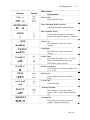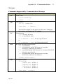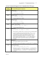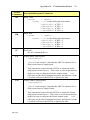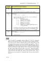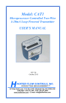
1
Model: HIT-2A Hoffer Intelligent Rate Indicator & Totalizer Hoffer Intelligent Model: HIT-2A Rate Indicator & Totalizer USER’S MANUAL USER’S MANUAL HP-306 November 2009 HP-306 May 2011 107 Kitty Hawk Lane, P.O. Box 2145, Elizabeth City, NC 27906-2145 800-628-4584 252-331-1997 FAX 252-331-2886 107 Kitty Hawk Lane • P.O. Box 2145 • [email protected] Elizabeth City, NC 27906-2145 www.hofferflow.comE-mail: 1-800-4584 • 252-331-1997 • FAX: 252-331-2886 www.hofferflow.com • E-mail: [email protected] NOTICE HOFFER FLOW CONTROLS, INC. makes no warranty of any kind with regard to this material, including, but not limited to, the implied warranties of merchantability and fitness for a particular purpose. This manual has been provided as an aid in installing, connecting, calibrating, operating, and servicing this unit. Every precaution for accuracy has been taken in the pr eparation of this manual; however, HOFFER FLOW CONTROLS, INC. neither assumes responsibility for any omissions or errors that may appear nor assumes liability for any damages that may result from the use of the pr oducts in accordance with information contained in the manual. HOFFER FLOW CONTROLS' policy is to provide a user manual for each item supplied. Therefore, all applicable user manuals should be examined before attempting to install or otherwise connect a number of related subsystems. During installation, care must be taken to se lect the correct interconnecting wiring drawing . The choice of an incorrect connection drawing may result in damage to the system and/or one of the components. Please review the complete model number of each item to be connected and locate the appropriate manual(s) and/or drawing(s). Identify all model numbers exactly before making any connections. A nu mber of options and accessories may be added to the main instrument, which are not shown on th e basic user wiring. Consult the appropriate option or accessory user manual before connecting it to the system. In many cases, a system wiring drawing is available and may be requested from HOFFER FLOW CONTROLS. This document contains pr oprietary information, which is pr otected by copyright. All rights are reserved. No part of this docu ment may be photocopied, reproduced, or translated to another language without the prior written consent of HOFFER FLOW CONTROLS, INC. HOFFER FLOW CONTROLS’ policy is to make running changes, not model changes, whenever an im provement is p ossible. T his affords our customers the latest in technology and en gineering. The information contained in this docum ent is subject to change without notice. Return Requests / Inquiries Direct all warranty and repair requests/inquiries to the Hoffer Flow Controls Customer Service Department, telephone nu mber (252) 331-1997 or 1-800-628-4584. BEFORE RETURNING ANY PRODUCT(S) TO HO FFER FLOW CONTROLS, PURCHASER MUST OB TAIN A RETURNED MATERIAL AUTHORIZATION (RMA) NUMBER FROM HOFFER FLOW CONTROLS’ CUSTOMER SERVICE DEPARTMENT (IN ORDER TO AVOID PROCESSING DELAYS). The assigned RMA number should then be marked on the o utside of the return package and on any correspondence. FOR WARRANTY RETURNS, please have the following information available BEFORE contacting HOFFER FLOW CONTROLS: 1. P.O. number under which the product was PURCHASED, 2. Model and serial number of the product under warranty, and 3. Repair instructions and/or specific problems relative to the product. FOR NON-WARRANTY REPAIRS OR CALIBRATIONS, consult HOFFER FLOW CONTROLS for current repair/ calibration charges. Have the following information available BEFORE contacting HOFFER FLOW CONTROLS: 1. P.O. number to cover the COST of the repair/calibration, 2. Model and serial number of the product and 3. Repair instructions and/or specific problems relative to the product. HFC 9708 LIMITED WARRANTY HOFFER FLOW CONTROLS, INC. ("HFC") warrants HFC's products ("goods") described in the specifications incorporated in this manual to b e free from defects in material and workmanship under normal use and ser vice, but only if such goods have been pr operly selected for the service intended, properly installed and properly operated and maintained. This warranty shall extend for a per iod of one (1) year from the date of delivery to the original purchaser (or eighteen (18) months if the delivery to the original purchaser occurred outside the conti nental United State s). This warranty is extended onl y to the or iginal purchaser ("Purchaser"). Purchaser's sole and exclusive remedy is the repair and/or replacement of nonconforming goods as provided in the following paragraphs. In the event Purchaser believes the goods are defective, the goods must be returned to HFC, transportation prepaid by Purchaser, within twelve (12) months after delivery of goods (or eighteen (18) months for goods delivered outside t he continental United States) for inspection by HFC. If HFC's inspection determines that the work manship or materials are defective, the goods will be either re paired or replaced, at HFC's sole dete rmination, free of additional charge, and the goo ds will be r eturned, transportation paid by HFC, using the lowest cost transportation available. Prior to r eturning the g oods to HFC, Purchaser must obtain a Retur ned Material Authorization (RMA) Number from HFC's Customer Service Department within 30 day s after discovery of a pur ported breach of war ranty, but no later than th e warranty period; otherwise, such claims shall be dee med waived. See the Retur n Requests/Inquiries Section of this manual. If HFC's inspection reveals the goods are f ree of defects in material and wor kmanship or such inspection reveals the g oods were improperly used, improperly installed, and/or improperly selected for service intended, HF C will notify the purchaser i n writing and will deliver the goods back to Purchaser upon (i) receipt of Purchaser's written instructions and (ii) the cost of tr ansportation. If Purchaser does not r espond within thir ty (30) days after notice from HFC, the goods will be disposed of in HFC's discretion. HFC does not warrant these goods to meet the requirements of any safety code of any state, municipality, or other jurisdiction, a nd Purchaser assumes all risk and li ability whatsoever resulting from the use thereof , whether used si ngly or in combination with other machines or apparatus. This warranty shall not apply to any HFC goods or parts thereof, which have been repaired outside HFC's factory or altered in any way, or have been subject to misuse, negligence, or accident, or have not been oper ated in accordance with HFC's pr inted instructions or have been operated under conditions more severe than, or otherwise exceeding, those set forth in the specifications for such goods. THIS WARRANTY IS EXPRESSLY IN LIEU OF ALL OTHER WARRANTIES, EXPRESSED OR IMPLIED, INCLUDING ANY IMPLIED WARRANTY OF MERCHANTABILITY OR FITNESS FOR A PARTICULAR PURPOSE. HFC SHALL NOT BE LIAB LE FOR ANY LOS S OR D AMAGE RESULTING, DIRECTLY OR I NDIRECTLY, FROM THE USE OR LOSS OF U SE OF THE GOODS. WITHOUT LIMITING THE GENERALITY OF THE FOREGOING, THIS EXCLUSION FROM LIABILITY EMBRACES THE PURCHASER'S EXPENSES FOR DOWNTIME OR FOR MAKING UP DOWNTIME, DAMAGES FOR WHICH THE PURCHASER MAY BE LIABLE TO O THER PERSONS, DAMAGES TO PRO PERTY, AND INJURY TO O R DEATH O F ANY PERSONS. HFC NEITHER ASSUMES NOR AUTHORIZES ANY PERSON TO AS SUME FOR IT ANY OTHER LIABILITY IN CONNECTION WITH THE SALE OR USE OF HFC'S GOODS, AND THERE ARE NO ORAL AGREEMENTS OR WARRANTIES COLLATERAL TO OR A FFECTING THE AGREEMENT. PURCHASER'S SOLE AND EXCLUSIVE REMEDY IS THE REPAIR AND/OR REPLACEMENT OF NONCONFORMING GOODS AS PROVIDED IN THE PRECEDING PARAGRAPHS. HFC SHALL NOT BE LIABLE FOR ANY OTHER DAMAGES WHATSOEVER INCLUDING INDIRECT, INCIDENTAL, OR CONSEQUENTIAL DAMAGES. Disclaimer Specifications are subject to change without notice. Some pages are left intentionally blank. HFC 9708 CONTENTS 1. Introduction --------------------------------------------------------------- 1 1-1 Model Number Designation ---------------------------------------- 2 2. SPECIFICATIONS ------------------------------------------------------ 3 2-1 General ---------------------------------------------------------------- 3 2-2 Inputs ------------------------------------------------------------------ 3 2-3 Battery Powered Version ------------------------------------------- 4 2-4 DC Power/Loop Powered------------------------------------------- 4 2-5 AC Power ------------------------------------------------------------- 4 2-6 Analog (4-20mA) Output Option ---------------------------------- 4 2-7 Pulse Output Option ------------------------------------------------- 5 2-8 Alarm Output Option ------------------------------------------------ 5 2-9 Physical --------------------------------------------------------------- 5 3. Theory of Operation ----------------------------------------------------- 7 3-1 Functional Blocks---------------------------------------------------- 7 3-1-1 User Interface--------------------------------------------------- 7 3-1-2 Preamplifier----------------------------------------------------- 7 3-1-3 Microcontroller------------------------------------------------- 7 3-1-4 Loop Driver----------------------------------------------------- 8 3-1-5 Pulse and Alarm Output--------------------------------------- 8 3-1-6 Communications Interface ------------------------------------ 9 3-2 System Response Time---------------------------------------------- 9 4. Installation ---------------------------------------------------------------- 11 4-1 Typical Input Connections----------------------------------------- 11 4-2 Typical Output Connections--------------------------------------- 14 4-3 Communications Connections------------------------------------- 17 4-4 Wiring ---------------------------------------------------------------- 17 4-5 Terminal Designations --------------------------------------------- 17 5. Configuration ------------------------------------------------------------ 19 5-1 Local Configuration ------------------------------------------------ 19 5-2 Default Configuration ---------------------------------------------- 22 5-3 Remote Configuration ---------------------------------------------- 22 6. Operation and Maintenance------------------------------------------- 23 6-1 Operation------------------------------------------------------------- 23 6-2 Maintenance --------------------------------------------------------- 24 6-3 Error Messages ------------------------------------------------------ 24 6-4 Analog Output Calibration----------------------------------------- 25 Appendix A – Default Configuration -------------------------------------- 27 Appendix B - Communications --------------------------------------------- 29 Message Format And Timeout --------------------------------------------- 29 Messages ---------------------------------------------------------------------- 31 HP-306 HP-306 Introduction 1 1. INTRODUCTION The HIT-2A is a microprocessor-based flow rate indicator and totalizer. The instrument displays flowrate and a resettable total and is compatible with all Hoffer t urbine flowmeters and the H.O.G. series positive displacement flowmeters. The instrument can accept a low le vel frequency signal, a pulse signal, or a co ntact closure on the input and provides a l inearized rate indication and total. The HIT-2A is fu lly configurable with K-factors, frequencies, and timebase being configured via the front panel key switches or the RS232 communications port. The configuration and monitoring can be performed using any PC based communications program (e.g., HyperTerminal) or ASCII terminal. The instrument is housed in an attractive NEMA 4X polycarbonate enclosure and can be mounted directly on a flowmeter or wall mounted using an optional mounting brackets or an EX enclosure. This instrument has been designed to conform to the EMC-Directive of the Council of Europ ean Communities 89/336/EEC and the following standards: Generic Emission Standard EN 61000-6-3 Residential, Commercial & Light Industry Environment. Generic Immunity Standard EN 61000-6-1 Residential, Commercial & Light Industry Environment. Electrostatic discharge requirements EN 61000-4-2 Radiated, radio-frequency, electromagnetic immunity EN 61000-4-3 Electrical fast transient/burst requirements EN 61000-4-4 Immunity to conducted disturbances EN 61000-4-6 HP-306 Introduction Model Number Designation MODEL HIT-2A TOTALIZER/FLOW RATE INDICATOR MODEL HIT-2A-( A )-( B )-( C )-( D )-( E )-( F ) ENCLOSURE STYLE INPUT POWER LOOP POWERED ANALOG OUTPUT OPTIONS MOUNTING SPECIAL FEATURES ENCLOSURE STYLE MODEL HIT-2A-( A )-( )-( )-( )-( )-( ) OPTION ( A ) (2) NEMA 4X ENCLOSURE, HIT-2A MOUNTED BEHIND CLEAR COVER. (3) EXPLOSION-PROOF ENCLOSURE. (3A) ATEX Exd ENCLOSURE, STANDARD BLUE (3B) ENCLOSURE FOR BRAZIL, GRAY (P) PANEL MOUNT - SURFACE MOUNTED ON CUSTOMER’S PANEL; NO ENCLOSURE BEHIND PANEL ON HIT-2A. (PD) PANEL MOUNT ENCLOSURE WITH CLEAR DOOR AND LOCK (4) NEMA 1 ENCLOSURE HIT-2A MOUNTED TO THE OUTSIDE OF CLEAR COVER FOR INDOOR/DRY INSTALLATION ONLY INPUT POWER MODEL HIT-2A-( )-( B )-( )-( )-( )-( ) OPTION ( B ) (A) INTERNAL BATTERIES (TWO EACH). THIS OPTION CAN NOT SUPPORT REDI-PULSE COILS. (B) 8 TO 30 VDC EXTERNAL POWER. (AC) UNIVERSAL 100-240 VAC @ 0.15A 50/60 HZ. (X) ENTER (X) IF LOOP POWERED ANALOG OUTPUT OPTION (C) OR (D) BELOW IS SELECTED. LOOP POWERED ANALOG OUTPUT MODEL HIT-2A-( )-( )-( C )-( )-( )-( ) OPTION ( C ) (C) LOOP POWERED 4-20MA OUTPUT (8 TO 30 VDC) (D) LOOP POWERED 4-20MA OUTPUT WITH INTERNAL BATTERIES HP-306 2 Introduction 2A OPTIONS MODEL HIT-2A-( )-( )-( )-( D )-( )-( ) OPTION ( D ) (L) 20 POINT LINEARIZATION. (RR) REMOTE RESET (AL) LOW ALARM* OPTO ISOLATED OPEN COLLECTOR. (AH) HIGH ALARM* OPTO ISOLATED OPEN COLLECTOR. *NOTE: EITHER LOW OR HIGH ALARM IS AVAILABLE, NOT BOTH. MOUNTING MODEL HIT-2A-( )-( )-( )-( )-( E )-( ) OPTION ( E ) (F) NEMA 4X STYLE 2 ENCLOSURE MOUNTED ON TURBINE. MUST BE USED WITH “X” RISER TURBINE OPTION. (FHT) 8" LONG TEMPERATURE RISER FOR NEMA 4X STYLE 2 ENCLOSURE MOUNTED ON TURBINE. REQUIRED WHEN FLUID TEMPERATURES EXCEED 140 DEG. F. USED WITH “X” RISER TURBINE OPTION. (FX) EXPLOSION-PROOF STYLE 3 ENCLOSURES MOUNTED ON TURBINE. MUST BE USED WITH “X” RISER TURBINE OPTION. (FXHT) 8" LONG TEMPERATURE RISER FOR EXPLOSION-PROOF STYLE 3 ENCLOSURES MOUNTED ON TURBINE. REQUIRED WHEN TEMPERATURES EXCEEDS 140 DEG. F. USED WITH “X” RISER TURBINE OPTION. (NP) NEMA 4X ENCLOSURE PIPE MOUNTING KIT, 2" PIPE OR SMALLER. SPECIFY IF PIPE IS VERTICAL OR HORIZINTAL. SPECIAL FEATURES MODEL HIT-2A-( )-( )-( )-( )-( )-( F ) OPTION ( F ) (CE) CE MARK REQUIRED FOR EUROPE (MIL) MIL-S-901D, “SHOCK TESTS, H.I. (HIGH IMPACT) SHIPBOARD MACHINERY, EQUIPMENT, AND SYSTEMS, REQUIREMENTS FOR;” DATED 17 MARCH 1989. MIL-STD-167-1, MECHANICAL VIBRATION OF SHIPBOARD EQUIPMENT (TYPE I – ENVIRONMENTAL & TYPE II – INTERNALLY EXCITED), 1 MAY 1974. (SP) ANY SPECIAL FEATURES THAT ARE NOT COVERED IN THE MODEL NUMBER USE A WRITTEN DESCRIPTION OF THE -SP. NOTES: 1. OPTO-ISOLATED OPEN COLLECTOR TRANSISTOR IS STANDARD WITH ALL UNITS. 2. A LOCAL RESET MAGNET IS STANDARD WITH ALL UNITS EXCEPT IF REMOTE RESETOPTION IS SELECTED. 3. WINDOWS® BASED SETUP DISC AND, IF REQUIRED, 6 FT COMMUNICATION CABLE. IF THREE OR MORE UNITS ARE ORDERED ON THE SAME PURCHASE ORDER ONE SET IS SUPPLIED AT NO CHARGE. SPARE BATTERIES: TADIRAN P/N TL2200/S 3.6V 5500mAh OR EQUAL (TWO BATTERIES ARE REQUIRED FOR BATTERY POWERED UNITS. ONE BATTERY IS REQUIRED FOR ALL OTHER POWER OPTIONS TO RETAIN TOTAL DISPLAY IF POWER FAILS. HP-306 Introduction This page intentionally left blank. HP-306 2B Specification 3 2. SPECIFICATIONS 2-1 General Display: Total: Total Units: Rate: Rate Units: K-factor: Linearization: Decimal Points: Accuracy: Temperature drift: 2-2 LCD, continuously powered 8 digits 0.26" high. Resettable from front panel. GAL, LIT, FT3, M3, BBL, & “blank”. 5 digits 0.5" high. /MIN, /HR, & /DAY The pulses per unit of Total (e.g. pulses/gallon) are configurable in the range 0.001 to 99,999,999. Up to 20 points. Decimal Point positions are fully configurable for both rate and total. 1 count 50 ppm/°C Inputs Magnetic Pickup: Frequency Range: Signal Type: 0.2 Hz to 5000 Hz. Low-level sinusoidal (30 mV P-P minimum). Opto-Isolated DC Pulse: Frequency Range: 0 Hz to 5000 Hz. Signal Type: DC pulse. High (Logic 1): 4 to 30 VDC Low (Logic 0): < 1 VDC Min Current: 0.5 mA Hystersis: 0.4 VDC Min Pulse width: 0.1 msec Contact Closure: Frequency Range: Signal Type: High (Logic 1): Low (Logic 0): Internal Pull-up: 0 Hz to 5000 Hz Contact closure to DC common Open or 4 to 30 VDC < 0.5 VDC 220 kΩ to +3.3 VDC HP-306 Specification Reset: Signal Type: High (Logic 1): Low (Logic 0): Min Current: Min On: Internal Pull-up: External Magnet: 2-3 Contact closure to DC common 4 to 30 VDC < 0.5 VDC 0.5 mA 25 msec 100 kΩ to +3.3 VDC Activates internal reed switch Battery Powered Version Type: Battery Life: Two C-size lithium battery packs. 6 years typical* 10 years typical* for external power. * 2-4 DC Power/Loop Powered Voltage: Current: Loop Burden: Supply Backup: Protection: 2-5 8 to 30 VDC < 4 mA 8 VDC maximum One (1) C-size Lithium battery Reverse polarity protected AC Power Voltage: Frequency: Current: Line Regulation: Protection: Supply Backup: 2-6 With the pulse output OFF. With pulse output ON 30% less. 100 to 240 VAC 47 – 440 Hz 150 mA 0.3%, typ Short circuit, Over voltage, & Over temperature One (1) C-size Lithium battery Analog (4-20mA) Output Option Scale: Accuracy: Temperature drift: Update Time: Connection: Protection: 4 – 20 mA follows rate. 0.02% of Full Scale @ 20ºC. 40 ppm/°C 2.0 seconds. Two wire. Reverse polarity protected HP-306 4 Specification 2-7 Pulse Output Option Type: Opto-isolated open collector (100 VDC, 100 mA). 1, 10, 100, or OFF See below. Divider: Rate & Duration: SPEED (Hz) Min on/off (msec) 2-8 1 500 2 250 4 125 8 62.5 Alarm Output Option Type: Function: 2-9 5 Opto-isolated open collector (100 VDC, 100 mA). Rate or Total Physical Temperature: Humidity: Packaging: Dimensions for Wall Mount enclosure: Operating: -4 °F (-20C) to 158 °F (70 C) 32 °F (0°C) to 140 °F (60°C) with AC power option. 0 – 90% Non-condensing. Wall Mount & Explosion proof 4.33" (110 mm) wide x 4.33" (110 mm) long 4.33" (110 mm) tall. HP-306 Specification This page intentionally left blank. HP-306 6 Theory of Operation 7 3. THEORY OF OPERATION The HIT-2A consists of six functional blocks. These functional blocks are the User Interface, Preamplifier, Microcontroller, L oop Driver, Pulse and Alarm Output, and Communications Interface. Loop Driver Flowmeter Input Preamp 4-20 mA Microcontroller Opto-isolated Outputs Pulse Output Alarm Output Communications Interface RS232 User Interface IRDA 3-1 Functional Blocks 3-1-1 User Interface The User Interface consists of a custom LCD display with 4 pus h buttons; OK, P, > (right arrow), and ^ (up arrow) and an optional external reset. Using the buttons and the displayed information, the user can enter setup parameters (rate units, pulses per unit of flow, etc.) as well as setup information for the pulse output and 420mA output. The optional external reset maybe used to reset the accumulated total to ze ro and clear the displayed accumulated total. 3-1-2 Preamplifier The Preamplifier accepts the inpu t from the flowmeter. T he Preamplifier applies amplification, low-pass filtering, and waveshaping to the input signal. The wave shaping function converts the signal into a squ are-wave before sending it to the Microcontroller. 3-1-3 Microcontroller The Microcontroller accepts the square-wave output of the preamplifier and performs all of the calculations that are required to control the Loop Driver. After measuring the frequency of the HP-306 Theory of Operation 8 square-wave, the Microcontroller uses the following equations to compute the flow rate and current. flowrate frequency x 60 FM xCF Kfactor Where: Kfactor = Is dependent on the Flow Calculation Method setting and is either the Average K-Factor or the Linearized K-Factor from the Frequency / K-Factor table. FM = Is the Flow rate Units setting of 0, 1, 2 or 3. Where “0” is for Seconds, “1” is for Minutes, “2” is for Hours and “3” is for days. CF = Is the Correction Factor setting. flowrate current 4mA 16mAx AF Where: AF = is the 20 mA maximum Flow Rate value. If the calculated flowrate is g reater than the AF setting, the current will be set to 24mA to signal an “Over-range” condition. After calculating the current, the Microcontroller digitally sends the current information to the Loop Driver. 3-1-4 Loop Driver The loop driver uses the digital information received from the Microcontroller to set the current of the loop. Th e Loop Driver supplies power to both the Preamplifier and Microcontroller. 3-1-5 Pulse and Alarm Output The Pulse and Alarm outputs are two optically isolated open collector outputs. The al arm output activates when the total flow or the rate reaches a user defined level. The pulse output activates to give a scaled pulse output indicative of the total flow. Both of these outputs are rated for 100 VDC at 100 mA. HP-306 Theory of Operation 3-1-6 9 Communications Interface The communication is provided through a RS232C interface to the Microcontroller. The external terminal device provides the power for the RS232 interface. The Communications Interface is used to configure and trouble-shoot the device. 3-1-7 Clearing Total The Total amount stored in HIT-2A memory can be cleared from the front panel program menu, by external momentary switch wired to the reset input, or by external magnet. The magnet has to be brought close to top of the front panel. 3-2 System Response Time The displayed Rate and Total are updated every two (2) seconds. The analog output response time to reach steady state due to a change in the flow rate is also approximately two (2) seconds. When flow stops, the time for the analog output to return to 4 mA will be between 3 and 12 seconds, depending on the Maximum Sample Time (MST) setting. MST is adjust ed using the NB= (DATA) command, where NB is a value between 1 and 80. The default MST setting is NB= 1. Adjusting the MST is on ly recommended for low flow applications where the minimum input frequency is below 1 Hz. HP-306 Theory of Operation This page intentionally left blank. HP-306 10 Installation 11 4. INSTALLATION The HIT-2A has an input conditioning circuit, which accepts signals from most frequency or pulse producing flowmeters. The input will interface directly to: Turbine Flowmeters Reed Switches Logic Signals Open Collector Outputs The input is protected for over voltage up to 50 volts. The flowmeter input (terminals 1 & 2) m ust be configured for th e selected signal type by appropriately setting the input selection jumpers found on the HIT-2A signal input board (see following for jumper positions). 4-1 Typical Input Connections MAG Coil & Reed Switch Pickups HP-306 Installation TTL Redi-Pulse Pick-up with DC Power Reset Input HP-306 12 Installation Loop Power with TTL Redi-Pulse Loop Power with Redi-Pulse Open Collector Output HP-306 13 Installation TTL Redi-Pulse with AC Power 4-2 Typical Output Connections Analog Output with DC Power HP-306 14 Installation Analog Output with AC Power TB L N HIT-2A AC/DC Power Supply + - GND/ Earth Loop Loop + Customer Load DCS Alarm Output HP-306 15 Installation 16 Analog Output and TTL Redi-pulse with AC Power JP4 L + 12 11 N GND/ Earth 1 JP2 2 10 3 9 4 8 5 7 6 SIG + SIG - + Pulse Output HP-306 Redi Pulse C B A Installation 4-3 17 Communications Connections Communications with the HIT-2A using a terminal or a PC u sing the Windows configuration program requires the use of t he HOFFER HIT2A-301 Communications Cable. The communication circuits of the HIT-2A are externally powered and the power for these circuits is supplied by the RS232 serial port of the computer/terminal. The serial port configuration must be set to the following: Baud rate: Data bits: Parity: Stop bits: Handshaking: 2400 8 none 1 None Molex DB9 0511100660 or Equivalent CD 1 6 DSR Rx 2 7 RTS Tx 3 8 CTS DTR 4 VDC1 VDC2 9 NC SIG COM 5 Pin 2 Pin 1 Hoffer HIT2A-301 Communications Cable 4-4 Wiring When connecting the HIT-2A, it is good practice to use shielded cable. The shield should be connected to earth ground near the instrument. The other end of the shield should not be connected. In order to comply with the re quirements for Electromagnetic Compatibility, as p er EMC-Directive 89/336/EEC of the Council of European Community, this wiring practice is mandatory. 4-5 Terminal Designations Terminal 1 2 3 4 5 6 7 8 9 10 11 12 Description Signal/Pulse Input (+) Signal/Pulse Input (-) Shield Reset Input VDC (+) VDC (-) / Reset Common Pulse out (-) Pulse out (+) Alarm (-) Alarm (+) 4-20 mA (-) 4-20 mA (+) HP-306 Installation This page intentionally left blank. HP-306 18 Configuration 19 5. CONFIGURATION The HIT-2A is fu lly configurable, with all parameters being stored in non-volatile memory. The instrument may be co nfigured using the front panel keys, a PC running Terminal Emulation software, a ASCII terminal, or a PC running the HIT-2A Configuration software. 5-1 Local Configuration Local configuration is accomplished using the four buttons below the display while viewing the configuration parameters on the display. The local configuration mode is entered by pressing the P button. Once in the local configuration mode each of the four buttons have a special purpose as detailed below. Press to increment digit or change selection. Press for next menu item. P Press to initiate selection operation and to accept selection. OK Press to move cursor one position to the right. HP-306 Configuration Display CLEArtot no Option Yes No 10000000 FAC NN Linear Average 00000.000 1.000 4999.981 Fr 01 2 to 20 0 to 5000 1.000 C FAC tot unit 100 0000000.0 tot d Number of Points Sets the number of entries in the linearization table. Frequency 1-20 Enter a frequency in Hz for each entry in the table. Decimal point is fixed. K-factor 1-20 Enter a k-factor in pulses/gal for each entry in the table. FAC01 1.000 Linearization Method Sets the flow calculation method to average K-factor or K-factor table. Average K-factor Enter average K-factor. A FAC 20 Clear Total Clears accumulated total and sets TOTAL display to zero. K-factor Decimal Point Set K-factor decimal point location. FAC d PointS Menu item Description Tag Number User defined 5-digit number. (#####) tA9 AuErAgE 20 0.001 to 99999.999 Correction Factor User defined number between 0.001 and 99999.999 to multiply flow and total. Default 1.0. 100 = GAL 110 = FT3 140 = LIT 150 = M3 180 = BBL Total Units Select Total units. If custom is selected all indicators are off. (gal, lit, ft3, m3, bbl, custom) Total Decimal Point Set Total decimal point location. HP-306 Configuration Display FLo u NN in Option SEC Min HrS dAY 00000.000 1 1 to 80 1.000 99.999 PuLSE F 8 PASS 1234 unit LoC no ALArNN oFF 100000.0 ALArN Max Sample Time Set maximum time in seconds to sample the input frequency. Default 1. Out High Sets flow rate value for 20 mA output. outHi oFF Rate Units Select RATE units. Out Low Sets flow rate value for 4 mA output. outLo PuLSE S Menu item Description Rate Decimal Point location Set Rate decimal point location. FL d SAPLE 21 oFF 1 10 100 1 2 4 8 Pulse Scale Sets scale for pulse out. 1, 10, 100 units of total for one pulse out. OFF- turns pulse out off. Pulse Frequency Sets frequency of burst of pulse out. (1, 2, 4, 8) 0000 to 9999 Password Sets 4-digit password. Default 0000. Yes No Lock Unit Locks the unit. oFF rAtE tot Alarm Function Select Rate or Total for alarm output. OFF- turns alarm function off. Alarm Out Sets value to activate the alarm output. Default 99999.999 HP-306 Configuration Display Option 0.0 rAtE PuL test no AL test no 5-2 Menu item Description Set Total Sets Total to user defined value. Set t Cur out 22 rAtE 4 12 20 Current Out Sets analog output to follow rate or predefined level. Yes No Pulse Output Test Outputs a test frequency of 1Hz, 50% duty cycle. Yes No Alarm Output Test Activates alarm output. Default Configuration The HIT-2A is configured by the factory before shipment. When the instrument is purchased with a Ho ffer Flowmeter or when calibration and configuration data are s upplied, the instrument is configured as specified. When the i nstrument is shipped without specific configuration information, the instrument is con figured with default values. Refer to Appendix A for a listing of the HIT-2A factory default configuration. 5-3 Remote Configuration The HIT-2A may be con figured communications interface. Refer t communications details. remotely via the RS232 o Appendix B for the HP-306 Operation and Maintenance 23 6. OPERATION AND MAINTENANCE 6-1 Operation A suitable pulse producing device or flow meter is wired to the HIT-2A Signal Input terminals 1 (Sig +) and 2 (Sig -). The Signal Input circuit must be configured for the connected input device using the appropriate jumper blocks. Internal batteries, external DC, or a loop current may provide power to the unit. For all power options other than internal batteries (A), if th e primary power is lo st, the internal backup battery will p rovide for continued operation of the totalizer. Once properly wired, the operation of the HIT-2A is automatic. The flow totalizer is updated every 2 seconds* with the latest total. If no input counts are recei ved the unit remains in a l ow power state to conserve power. The flow total may be cleared by th e front panel switch sequence or by a contact closure on the remote reset terminal to circuit common. To reset the un it from the front panel, the following key sequence is required: Press P Press OK Press ▲ Press OK Press ▲ CLEArtot is displayed To enter edit mode. To select yes To clear total To return to operating mode The flow rate indicator m easures the flow rate once eve ry 2 seconds * and display the flow rate. If the input pulses are not detected within the maximum sample time (1 to 80 seconds), a flow rate of zero (0.00) is indicated. The analog output is scaled based on the user selected zero and full scale and the measured flow rate. The pulse output generates a bur st of pulses every 2 seconds accordance with the instrument setup of pulse scaling. * * A large sample time setting and internal math operations may delay the update rate. HP-306 in Operation and Maintenance 6-2 24 Maintenance The only scheduled maintenance for the HIT-2A is periodic battery replacement. The instrument has a b attery monitor feature which illuminates when the lithium battery voltage approaches its end of life. A descriptor, “LO BAT”, illuminates when the battery voltage falls below this predetermined value. The low battery detector operates correctly with all power options. The battery, or batteries, should be replaced within several weeks of the first occurrence of low battery warning. Left unattended, the unit may become inaccurate, cease t o operate, lose setup inform ation, or malfunction. The batteries should be replaced one at a time to avoid interrupting the power. 6-3 Error Messages The HIT-2A is provided with extensive self checking which is used in reporting malfunctions or unusual operating conditions. When an error occurs, the display will flash with an error message until the user presses the OK button acknowledging the error condition. O nce an error condition is ackn owledged, the error m essage will n ot be displayed again for 60 seconds if the cause of the error is still present. If the alarm output is active from an alarm caused by a rate or total condition, depressing the OK button while the display is sh owing the rate and total will reset the alarm output if the condition that caused the alarm is no longer present. If the alarm output is active because of a test command, depressing the OK button will n ot reset the alarm output. The following table illustrates the Error Messages, the problem or cause, and a recommended corrective action: HP-306 Operation and Maintenance ERROR MESSAGE EtotAL EPuLSE CAUSE 25 CORRECTIVE ACTION Total rollover. None Pulse out overflow. Use different pulse scaler or lower totalizer decimal point EErES EEPROM reset to factory defaults. Consult factory ErAtE Flow rate exceeds the flow rate display capability. EFLo Flow rate exceeds the 20 mA flow rate setting. LO BAT Low battery. 6-4 Reduce flow rate or use lower flow rate decimal point Reduce flow rate or increase 20 mA flow rate setting Replace battery(ies) Analog Output Calibration The 4-20 mA analog output has been accurately set to 20.000 mA by the factory. No adjustment is required. The 4-20 mA output may be verified periodically by installing a digital milliamp meter in series with the analog output and simulating a fu ll scale or over range flow rate. HP-306 Operation and Maintenance 26 This page intentionally left blank. HP-306 Appendix A – Default Configuration 27 APPENDIX A – DEFAULT CONFIGURATION Factory default configuration: FIELD CL DN FC KD AK NP F01 F02 F03 F04 F05 F06 F07 F08 F09 F10 F11 F12 F13 F14 F15 F16 F17 F18 F19 F20 K01 K02 K03 K04 K05 K06 K07 K08 K09 K10 K11 K12 K13 K14 Value No 10000000 0 (Average) 3 1.00 20 4999.981 4999.982 4999.983 4999.984 4999.985 4999.986 4999.987 4999.988 4999.989 4999.990 4999.991 4999.992 4999.993 4999.994 4999.995 4999.996 4999.997 4999.998 4999.999 5000.000 1.00 1.00 1.00 1.00 1.00 1.00 1.00 1.00 1.00 1.00 1.00 1.00 1.00 1.00 HP-306 Appendix A – Default Configuration FIELD K15 K16 K17 K18 K19 K20 CF TU TD FM RD NB LF AF PS FO PA LK UA AL ST OC TP AS 28 Value 1.00 1.00 1.00 1.00 1.00 1.00 1.000 100 (GAL) 1 1 (MIN) 3 01 00000.000 99.999 0 (OFF) 8 1234 No Off 99999.981 00000.000 0 (Rate) No No HP-306 Appendix B - Communications 29 APPENDIX B - COMMUNICATIONS Message Format And Timeout Communication messages consist of a st ring of ASCII characters terminated by a carriage re turn character. The maximum message length coming to the HIT-2A is 20 characters, including the carriage return. Th e HIT-2A will tran smit no more than 35 characters before transmitting a carriage return. If a m essage longer than A 2 0 characters command is sent, the instrument responds with “Command Sequence is Too Long!<NL>” If an unrecognized or invalid command is sent, the instrument responds with “Invalid Command! <NL>” The sending unit RS232C serial port configuration must be configured as follows: Baud rate: Data bits: Parity: Stop bits: Handshaking: 2400 8 none 1 none The HIT-2A echoes all re ceived messages and then transmits a response string terminated with a carriage return. If t he sending unit takes longer than one minute to send a message, the HIT-2A aborts the message by clearing the receive buffer. If the sending unit (PC or other such device) wishes to change a setting on the HIT-2A, th e sending unit shall follow the command with an equal sign (“= ”) with the data following immediately after th e equal sign. The carriage return terminates the message. Any HIT-2A response that sends data back to th e sending unit shall have an equal sign (“= ”) followed by the data. Space is allowed between the equal sign and the data on the return message, but the total message length is limited to 35 characters. HP-306 Appendix B - Communications 30 READ Example: If the sending unit wishes to read the number of points that the HIT-2A has in the K factor table, the sending unit shall send “NP<CR>” The HIT-2A echoes the sent message, and responds with “NUM PTS = 2<CR>” WRITE Example: If the sending unit wishes to change the number of points to 20 in the K factor table, the sending unit shall send “NP=20<CR>” The HIT-2A echoes the sent message and responds with “NUM PTS = 20<CR>”. The HIT-2A checks the ranges for data and rejects writes that a re not within the allowed range. If the sending unit sends data that is not within the allowed range, the HIT-2A echoes the sent message and responds with the value that is currently stored in the HIT-2A. Example: If the sending unit wishes to change the max sample time to 2000 from the previous setting of 10, the sending unit shall send “NB=2000<CR>” The HIT-2A echoes the sent message, and responds with “MAX M TIME= HP-306 10<CR>”. Appendix B - Communications 31 Messages Commands Supported By Communications Messages Command 1 CL Description/Allowed Data/Response Clear Total “0” to “99999999” “TOTAL DN = 0” Tag Number “0” to “99999999” “TAG NUM = (DATA)” The first three digits are the units code for total. Changing these digits will change the TU settings. FC Linearization “0” = Average K factor “1” = Linearization table “F C METHOD = AVG” for Average K factor or “F C METHOD = LIN” for Linearization table KD K Factor Decimal Point Location “0” for 00000000. “1” for 0000000.0 and all K Factors are less than 9999999.9, otherwise not allowed “2” for 000000.00and all K Factors are less than 999999.99, otherwise not allowed “3” for 00000.000 and all K Factors are less than 99999.999, otherwise not allowed “K-FAC DECL=(DATA)” AK Average K Factor “0.001” to “99999.999” “999999.99” “9999999.9” “ 99999999” “AVG KFAC HP-306 if KD = 3 if KD = 2 if KD = 1 if KD = 0 =(DATA)” Appendix B - Communications Command NP Description/Allowed Data/Response Number Points in the Table “2” to “20” “NUM PTS F## 32 =(DATA)” Frequency 1-20 F01 has a range of “0.000” to the value of F02 minus 0.001; F20 has a range of the value from F19 plus 0.001 to “5000.000”; Frequencies F02 to F19 must be 0.001 greater than the previous frequency and 0.001 less than the next frequency. “FREQ ## =(DATA)” for F01 through F20. Data to fixed three decimal places. K## K-Factor 1-20 “K-FACT # =(DATA)” for K01 through K09. “K-FACT ## =(DATA)” for K10 through K20. DATA to decimal places as per KD command. CF Correction Factor “0.001” to “9999999.999” “CORR FACT =(DATA)” TU Total Units “100” “140” “110” “150” “180” for gallons for liters for cubic feet for cubic meters for barrels All other integer values from 0 and less than 999 will map to custom units “TOT UNITS =(DATA)” (DATA) shall be: “GAL” for gallons “LIT” for liters “FT3” for cubic feet “M3 ” for cubic meters “BBL” for barrels “CUS” for custom These three numbers will be the same as the first three digits of the tag number. Changes to this menu shall cause the changes to the tag number. HP-306 Appendix B - Communications Command TD 33 Description/Allowed Data/Response Total Decimal Point Location “0” for 00000000. “1” for 0000000.0. If UA set to Total and AL is greater than 9999999.9 it not allowed. “2” for 000000.00. If UA set to Total and AL is greater than 999999.99 it not allowed. “3” for 00000.000. If UA set to Total and AL is greater than 99999.999 it not allowed. “FLOW DEC L=(DATA)” FM Rate Units “0” for seconds “1” for minutes “2” for hours “3” for days “FLOW UNITS=(DATA)” (DATA) shall be: “SEC” for seconds “MIN” for minutes “HR ” for hours “DAY” for days RD Rate Decimal Point Location “0” for 00000. “1” for 0000000.0 and AF (and AL if UA set to Rate) is less than 9999999.9, otherwise not allowed. “2” for 000000.00 and AF (and AL if UA set to Rate) is less than 999999.99, otherwise not allowed. “3” for 00000.000 and AF (and AL if UA set to Rate) is less than 99999.999, otherwise not allowed. “RATE DEC L=(DATA)” NB Max Sample Time “1” to “80” “MAX M TIME=(DATA)” LF Out Low “0.000” to a maximum value of the Out High setting “4mA FLOW HP-306 =(DATA)” Appendix B - Communications Command AF Description/Allowed Data/Response Out High Minimum is the Out Low Setting (LF) to a maximum of the following: “99999.999” if RD = 3 “999999.99” if RD = 2 “9999999.9” if RD = 1 “ 99999999” if RD = 0 “20mA FLOW =(DATA)” PS Pulse Scale “0” “1” “10” “100” for OFF for 1 for 10 for 100 “PULS SCALE=(DATA)” (DATA) shall be: “OFF” for OFF “1” for 1 “10” for 10 “100” for 100 FO Pulse Frequency “1” “2” “4” “8” “PULS FREQ =(DATA)” PA Password “0” to “9999” “PASS WORD =(DATA)” LK Lock Unit “0” for NO “1” for YES “LOCK UNIT =(DATA)” (DATA) shall be: “YES” for YES “NO” for NO HP-306 34 Appendix B - Communications Command UA Description/Allowed Data/Response Alarm Function “0” for OFF “1” for RATE “2” for TOTAL “ALARM FUNC=(DATA)” (DATA) shall be: “OFF” for OFF “RAT” for RATE “TOT” for TOTAL AL Alarm Out “0.001” to a maximum defined as follows: If UA is RATE: “99999.999” “999999.99” “9999999.9” “ 99999999” if RD = 3 if RD = 2 if RD = 1 if RD = 0 If UA is Total or Off: “99999.999” “999999.99” “9999999.9” “ 99999999” if TD = 3 if TD = 2 if TD = 1 if TD = 0 “ALARM OUT =(DATA)” 1 ST Set Total “0.000” to a maximum defined as follows: “99999.999” if TD = 3 “999999.99” if TD = 2 “9999999.9” if TD = 1 “ 99999999” if TD = 0 “TOTAL = (DATA)” (DATA) = “0” to the following maximums: “99999.999” if TD = 3 “999999.99” if TD = 2 “9999999.9” if TD = 1 “ 99999999” if TD = 0 HP-306 35 Appendix B - Communications Command OC Description/Allowed Data/Response Current Out “0” - Current output follows rate. “1” - Current output set to 4mA. “2” - Current output set to 12mA. “3” - Current output set to 20mA. For “0”, response = For “1”, response = For “2”, response = For “3”, response = PR 36 “ “ “ “ Output Output Output Output equal to input.” is 4mA.” is 12mA.” is 20mA.” Pulse Output Controlled By PS and FO “ Pulse Output Released ” The PS and FO menus shall control the pulse output. Used to terminate the TP command. TP Output 1Hz Test Frequency for Pulse Output “ Test Pulse Output ” Sets output to 1Hz, 50% duty cycle signal. This mode is for factory test. RA Release Alarm Output for Control According to Menu Settings “ Alarm Released ” Releases alarm output for control by the alarm output settings. AS Alarm Output Test “0” – Alarm output is set low. “1” - Alarm output is set high. For “0”, response = “ Alarm Active ” For “1”, response = “ Alarm Released ” After using the “AS” command, you must initiate a RA command to allow HIT-2A to return to normal operation. HP-306 Appendix B - Communications 37 System Commands Supported by Communications Messages System Command OI Description/Response/Comments Output 4mA “ Output is 4mA.” Current output set to 4mA. MO Output 12mA “ Output is 12mA.” Current output set to 12mA. OM Output 20mA “ Output is 20mA.” Current output set to 20mA. OF Output = Rate (Input) “ Output equal to input.” Current output follows rate. AA Auto Data “F (DATA) R (DATA) T (DATA)” The response, not the echo, is sent every two seconds until it receives another message from the master. The (DATA) following the F denotes the frequency of the pulses to a precision of three places past the decimal, the (DATA) following the R denotes the rate to a precision of three places past the decimal, and the (DATA) following the T denotes the total to a precision of three places past the decimal. DA Dump All All of the responses in previous table. The HIT-2A gives all responses except for the CL command. UI Unit Identification “UNIT MODEL=HIT2A XX YY.ZZ” Model and software number for the unit. XX is the hardware revision number, YY.ZZ is the software revision where YY is the major software revision and ZZ is the minor software revision. HP-306 Appendix B - Communications System Command 38 Description/Response/Comments RT Read Total “TOTAL = (DATA)” (DATA) = “0” to the following maximums: “99999.999” if TD = 3 “999999.99” if TD = 2 “9999999.9” if TD = 1 “ 99999999” if TD = 0 RR Read Rate “FLOW = (DATA)” (DATA) = “0” to the following maximums: “99999.999” if RD = 3 “999999.99” if RD = 2 “9999999.9” if RD = 1 “ 99999999” if RD = 0 ST1 Set Total See ST command above. CN Adjust 4mA output point “CN=#(DATA)” (DATA) is the integer value that the HIT2A sends to the 420mA converter to output 4mA This parameter is passed to the HIT2A to adjust the 4mA output point of the device. This value is used in production at the test step to calibrate the 4mA output point. “CN” will cause an Invalid Command response and absence of the # symbol will cause the HIT2A to ignore the data. CM Adjust 20mA output point “CM=#(DATA)” (DATA) is the integer value that the HIT2A sends to the 420mA converter to output 20mA This parameter is passed to the HIT2A to adjust the 20mA output point of the device. This value is used in production at the test step to calibrate the 20mA output point. “CM” will cause an Invalid Command response and absence of the # symbol will cause the HIT2A to ignore the data. HP-306 Appendix B - Communications System Command SA 39 Description/Response/Comments Set Alarm Output On “ Alarm Active ” Sets the alarm output active regardless of the settings. US Unit Status "UNIT STAT = <DATA>" Requests the status. The values for <DATA> with no or only one error present are: “0” – No Errors present. “128” – EPULSE error (0x080) “129” – ETOTAL error (0x081) “130” – ERATE error (0x082) “132” – EFLOW error (0x084) “129” – EERES error (0x088) (EEPROM reset to factory defaults) If multiple errors occur, the error codes are logically OR-ed. For example, if the unit has an ETOTAL and ERATE error occurring at the same time, the <DATA> = “131” (0x83). CS Clear Status " Status Cleared " Clears all errors. Notes: 1. The CL a nd ST commands work as follows. T he ST c ommand shall store the present value of the total in Non-Volatile memory. This total in no n-volatile memory shall be the initial total in the event that device power is removed and then re-applied. The CL command will clear t he total in the device and the stored to tal in EEPROM but retain the present total in a volatile (RAM) memory location and keep it as the old total value. Removal of power from the unit causes this old total value to be lost. When the HIT2 a receives the ST<CR> from the PC, it s hall echo back the old total value until the unit adds any v alue to the present total. If th e HIT2a receives a second CL command, the old total value shall be set to 0. HP-306 Appendix B - Communications 40 For example, if the prese nt total is 123.45 and the HIT2a receives CL<CR>, the present total is cleared (set to 0.0000), the total in EEPROM is cleared , and the old total value is 1 23.45. If th e HIT2a receives ST<CR>, the HIT2a echoes with the total 123.45, the old total value. If t he HIT2a receives pulses to c ause the present total to increment to 0.01 and then receives a ST<CR>, the HIT2a will echo 0.01, or the present total. The unit mimics this behavior on the display with the Clear Total Menu and the Set to tal menu. The reset total input (magnet or terminal input) acts the sam e as the receipt of a CL<CR> from the communications link. HP-306