1
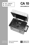
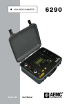
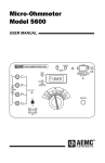
MICROHMMETER CA-10
(Cód 7 70 118 )
USER’S MANUAL
(M981184-99A-GB)
(c)
CIRCUTOR S.A.
-- MICROHMMETER CA- 10 ----
Page Nº 1
1.- SAFETY PRECAUTIONS
1.1.- MEASUREMENT
Before any measurement, check that the resistance to be tested is not live.
Check that the battery has a charge sufficient for the requirements of the
measurement, otherwise, recharge it.
1.2.- MAINTENANCE
To preserve the service life of the battery, take care not to exceed a charge time
longer than 14 h for a completely discharged battery.
Before opening the case, check that the instrument is disconnected from any
supply source. When replacing the battery, reconnect the wires according to the
polarity (+ red and – black).
When reclosing the case, reconnect the linking cables connecting the supply
board, on the back of the case, to the upper board mounted on the chassis.
2. PRESENTATION
The CA 10 MICROHMMETER is a portable 2000 count digital ohmmeter
designed for the measurement of very low resistance values. Presented in a
robust worksite case, the CA 10 MICROHMMETER is an autonomous
instrument, powered by a cadmium nickel battery, with a dual voltage charger
(110 V/220 V) incorporated.
6 ranges from 0-2000 µΩ to 200 Ω are available to the user.
The CA 10 MlCROHMMETER operates according to the 4 wire method: a DC
current I is injected through the resistance under test, a measurement of voltage
U is made at the terminals of the resistance. The instrument then displays the
value of the resistance corresponding to the ratio U/I.
The CA 10 MICROHMMETER has as its principal application the precise
measurement of the resistance of the windings of rotary machines or
transformers, switch contacts, motor collectors, cable junctions, solder points...
3. GENERAL FEATURES
3.1/ CASE
• Work site plastic case with 50% glass
-- MICROHMMETER CA- 10 ----
•
•
•
Page Nº 2
Protection rating to CEI 529, IP 520 lid open/IP 543 lid closed
Dimensions:390 x 260 x 250 (L x I x H)
Mass:approx 8 kg
3.2/ POWER SUPPLY
• Cadmium nickel battery (6 V - 7 A.h) rechargeable on mains supply with
incorporated dual voltage charger (110 V/220 V)
• Automatic power cut out if the current terminals are in the air for more than
4 minutes approximately
• Voltage operating range:4.5 V to 7 V.
3.3/ SERVICE LIFE
• 200 to 300 measurements of 8 seconds with a measurement current of 10
A.
• Approx. 900 measurements of 30 seconds with a measurement ourrent of 1
A.
• Approx. 5000 measurements of 30 seconds with a measurement current
less than or equal to 0.1 A.
• The «LOW» indicator shows, when flashing, a remaining service life
sufficient for about 10 measurements at 10 A and more than 100 for the
others.
3.4/ CONNECTION
• Four large terminals for 4 mm diameter banana plugs or spade connectors
with a minimum opening of 6 mm.
3.5/ DISPLAY
• 2000 counts,
• 7 segments LCD, 3% digits, 18 mm height,
• good readability down to 1 lux,
• «1 » on the left of the display indicates range overload,
• «-» on the left of the display indicates a reversal of connection of the
measuring leads (crossing the voltage or current leads).
• 2 second time constant (approx.) for the display to settle whatever the
resistance being measured (example: inductive winding).
-- MICROHMMETER CA- 10 ----
Page Nº 3
4. ELECTRICAL SPECIFICATIONS
• Max. permitted overload on the measurement terminals:380 V rms,
• Protection by HBC 380 V fuse and oversized sensitive parts, class 2
instrument to CEI 348 (rated insulation voltage 250 V rms),
• Minimum dielectric strength 1500 V for the terminals and 3000 V for the
power socket,
• Electrostatic discharge level 2 (4 kV) to CEI 801-2,
• Radiated field level 2 (3 V/m) to CEI 801-3,
• Electric shocks on supply socket level 4 (3kV) to CEI 801-5.
4.1/ MEASUREMENT RANGES
Ranges
0-2000µΩ 0-20µΩ
0-200µΩ 0-2000µΩ 0-20Ω
0-200Q
Resolution
10µΩ
100µΩ
1µΩ
10µΩ
100µΩ
Measureme 10A
nt current
1A
1A
100mA
10mA
10mA
Typical
accuracy in
the
reference
conditions
Accuracy
max. in the
reference
0,25%
reading
± 1 count
0,25%
reading
± 1
count
0,25%
reading
± 1 count
0,25%
reading
± 1 count
0,25%
reading
± 1 count
0,5%
0,5 %
reading reading
± 1 count ± 1 count
0,5%
reading
± 1 count
0,5%
reading
± 1 count
1pµΩ
0,25%
reading
±2
counts
0,5%
0,5%
reading
reading
± 2 counts ± 1 count
4.2/ REFERENCE CONDITIONS
• Ambient temperature:23’C ±3ºC
• Relative humidity:40% to 60% HR
• Supply voltage:6 V ∗± 0.1 V
4.3/ VARIATION IN THE WORKING RANGE
Type of
distortion
Limits of working range
Temperature
-10º C to + 55º C
Humidity
10% to 90%
Voltage
4,5V à 7V
•
Average variation % of the measurement in relation to
the reference conditions
Typical
0,1% measur./10ºC
_____________
± 0,1 %
Transportation and storage temperature:-20’C to 55’C
5. DESCRIPTION
(Cód 7 70 118 )
Max
0,25% measur./10ºC
0,5% max
in the range working
±0,15 %
-- MICROHMMETER CA- 10 ----
Page Nº 4
¬4 big terminals for connection with 4 mm diameter plugs or by spade clips
tightened under the terminals. C1 and C2 correspond to the current outputs; P1
and P2 to voltage measurements. The terminals are marked by colours
corresponding to those of the connection accessories:C1 and P1 are red, P2
and C2 are red, P2 and C2 are black.
- Rotary switch with 6 positions to select the range and the measurement
current (from 2000 pQ/1 0 A to 200Q/0.01A).
® ON/OFF button for switching the instrument ON/OFF.
¯ I nvertor to invert the measurement current to take into account the possible
presence of thermal electromotive forces (principally for the 2000 pQ range).
°LCD.
± “LOW” and CHARGING” indicators of battery condition.
² Measurementcurrent ”FAULT” indicator.
³Thermal safety ”THERMAL PROTECTION” indicator.
´Power supply mounted socket for connection of the battery charger lead.
µDirectly accessible screwed fuse holder
6. INDiCATORS
6.1/ BATTERY
• LOW
-- MICROHMMETER CA- 10 ----
Page Nº 5
The battery voltage is permanently checked. When it is getting low, the flashing
red “LOW” indicator warns the user that there is only enough power for a few
measurements. It becomes urgent to charge the battery. If the user reaches the
limit of battery use, the red «LOW » light stops flashing, the instrument is out of
service and will not make any more measurements. It is then essential to
recharge the battery. Once the battery is recharged, press the ON/OFF button
twice (®) to switch on the instrument again.
• CHARGING
The green «CHARGING» light indicates that the battery is currently being
recharged. This indicator will remain lit as long as the instrument is connected
to the power supply.
6.2I VALIDATING MEASUREMENT ( ² )
• FAULT
• The current input by the instrument into the measurement circuit is
electronically checked. The «FAULT» light comes on in the two following
cases: If this current is null (open circuit or protective fuse in the instrument
has blown). The user must check the circuit (clamp contact, condition of the
resistance, condition of the two fuses) because the measurement isn’t valid.
Note that if the circuit isn’t re-closed after approx. 4 minutes the instrument
switches off automatically.
If the measured resistance is very high in relation to the range used. The user
should then change to the higher ranges.
6.3/ THERMAL PROTECTION ( ³ )
• THERMAL PROTECTION : For the 2000 µΩ range (10 A), thermal
protection of the electronics is provided by an internal thermostat which
interrupts the 10 A current in the case of prolonged use. When overheating,
the «THERMAL PROTECTION indicator lights and blocks the 2000 µΩ
range. The other ranges are nevertheless usable. The 2000 µΩ range will
again be accessible as soon as the light goes out (approx. 10 minutes).
7. ELECTRICAL PROTECTION
Protection of the instrument from incorrect use is by oversized sensitive
components and by fuses accessible from the front panel.
The fuses F1 and F2 (see 10 p.6), with a high breaking capacity, provide good
protection for the instrument in case of incorrect connection by the operator
-- MICROHMMETER CA- 10 ----
Page Nº 6
(380 V rms applied to the socket terminals two by two in any order).
To make a rapid test of the fuses, simply short-circuit terminals C1and C2 (see
1 p.6), and switch on the instrument by pressing the ON/OFF button (see 3 p.6).
If the “FAULT” light ( ² ) comes on this confirms that at least one of the two
fuses, F1 or F2, is blown.
In this case replace the blown fuse with one of the correct type and value, 8 A
380 V .
8. OPERATING PROCEDURE
8.1/ lN GENERAL
• Check that the resistance to be tested isn’t live,
• Switch ON the instrument by pressing the ON/OFF button (®),
-- MICROHMMETER CA- 10 ----
Page Nº 7
*Connect the resistance to be measured according to the diagram shown next
to the measurement terminals (¬). With the instrument operating according to
the 4 wire method, check the correct position of the uoltage measurement
points. To do this, apply the voltage measurement instruments (the 10 A clamps
supplied with the instrument can be used both to input the measurement current
and to measure the voltage) at the precise points defining the resistance
terminals.
•
•
•
•
•
Select the measurement range using the range switch. The user should be
aware that the choice of a low measurement range implies a high test
current.
If you don’t know the order of magnitude of the resistance, we advise using
the highest range (200 Ω/0.01A).
Read the value on the LCD directly in the unit indicated by the range switch.
The appearance of the “--“ sign on the left of the display indicates poor
connection of the measurement leads:crossing the voltage or current leads.
Simply change over the current connections C1 and C2, or the voltage
terminals P1 and P2 .
The appearance of the “1” digit on the left of the display indicates range
overload, so you should change to a higher range. Nevertheless, if the digit
“1” is still displayed even on the highest range (200 Ω/0.01A) this means that
the value of the resistance under test is above 199.9 Ω (max. value of the
measurement range of the instrument).
-- MICROHMMETER CA- 10 ----
•
•
Page Nº 8
To obtain higher accuracy, reduce the range and on the range switch read
the value of the test current corresponding to this new range to guard
yourself against problems due to the injection of a current that is too high.
To switch off the instrument, press the ON/OFF button again. the display
should then go out.
NOTE: During any operation, it is important to keep a watch on the different
indicators which were explained on LED INDICATORS.
8.2/ VERY LOW RESISTANCES
When measuring very low resistances, the presence of thermal electromotive
forces can reduce the accuracy of the measurement. You can eliminate their
effect by reversing the direction of the current. The real measurement will then
be obtained by taking half the value of the sum of the absolute values of the
«+» and «-» readings as indicated below:
•
•
•
•
Take a normal measurement as described in «In general» (see preceding
paragraph «IN GENERAL») and note down the value «A » displayed. By
definition, the range will be «2000 µΩ» because you are making a test of
very low resistance,
Press the invertor (see 4 p. 6) changing it from the high position (+1) to the
low position (-1) and hold it for the time required ta note down the displayed
value «B». This should be preceded by the «-» sign indicating that you have
reversed the measurement current.
Make the following calculation: IAI + IBI
The result of this calculation gives the precise value of the resistance tested
overcoming problems of interference voltages in the measurement circuit.
NOTE: To benefit from all the accuracy guaranteed by the instrument, take
measurements taking care to make the current lines homogeneous in the
measured zone.
-- MICROHMMETER CA- 10 ----
Page Nº 9
9. MAINTENANCE
9.1/ RECHARGING THE BATTERY
• The incorporated battery is dual voltage (110 V/220 V); switching is done
inside the instrument by a sliding switch on the supply board
• A small plate fastened by screws below the charger socket on the front
panel indicates the voltage that the charger is programmed for.
• Check that the supply voltage matches the voltage marked on the voltage
supply plate.
• If the programming of the charge voltage has to be changed, then this little
plate should be turned over so that it always matches the programmed
voltage and the voltage indicated on the front
• panel.
• Connect the power lead to the socket.
• Once the lead has been connected to the power supply, the “CHARGING”
light comes on, indicating that the battery is being charged.
• The charger is protected against incorrect programming of the power supply
by internal electronic protection. f this protection comes into play, wait
approx. one minute before switching on the charger again (The cooling time
of the protective varistance).
Voltages permissible on the charger:
187 V to 253 V (230 V rated) frequency 47 Hz to 450 Hz
94 V to 127 V (110 V rated) frequency 47 Hz to 450 Hz
Battery charge time:
-14 hours (for a completely discharged battery)
-Number of charge/discharge cycles:more than 300 cycles
-Once the battery has been recharged, press ON/OFF twice to switch on the
instrument again.
NOTE: During charging measurement is possible. Wait for the instrument to
come on, according to the condition of the battery, then make measurements.
The charger capacity (800 mA) makes it possible to use the 20 µΩ200 µΩ, 2000
µΩ, 20 Ω, 200 Ω ranges continuously and the 2000 µΩ range temporarily
-- MICROHMMETER CA- 10 ----
Page Nº 10
9.2/ REMOVING THE LID
To unclip the lid of the case, apply vertical pressure to the back of the lid while
holding it.
9.3/ OPENING THE CASE
To open, first remove the lid, then use the allen key which is in the pouch in the
lid of the case. Unscrew the six screws holding the chassis located under the
case.
Lift away the chassis without forgetting to disconnect the linking cables 1 and 2
connecting the power
supply board located at the bottom of the case to the upper board fixed on the
chassis.
-- MICROHMMETER CA- 10 ----
Page Nº 11
9.4/ CHANGING THE BATTERY
•
Affer having dismantled the base plate (see p.33 «OPENING THE CASE»),
unscrew the two butterfly screws on the battery support.
•
Rernove the battery support plate.
•
Disconnect, then remove the battery, and exchange it for the recommended
battery «BATTERY N’2 Cd/Ni», reference P01.2960-12
9.5/ CLEANING THE CASE
Preferably use a soft cloth moistened with soapy water.
Avoid using alcohol or oil based products.
9.6/ CALIBRATION
It is essential that all measuring instruments are regularly calibrated. For
occasional daily use, we recommend that an annual check be carried out. When
the instrument is used continuously every day, we recommend that a check is
made every 6 months.
9.7/ REPAIR
Maintenance, repairs under or out of guarantee: Please return the product to
your distributor.