1
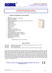
43-200 Pszczyna, ul. Staromiejska 31b
tel. 032 326 30 70, fax 032 447 73 30
www.gorke.com.pl, e-mail: [email protected]
USER’S MANUAL
type of the device: 4-channel, 1000m set
contains of: IDO 500 identifying receiver and 4-key RNB 101S sender
TECHNICAL PARAMETERS
•
•
•
•
•
•
•
•
•
•
•
•
•
•
•
•
•
•
type of receiving module: superheterodyne
sensitivity: -115 dBm
frequency: 433,92 MHz
radio transmission: KeeLoq hopping code by Microchip
Technology
memory capacity: 500
supply: 12 V AC/DC or 24 V AC/DC
power consumption:
static: 40 mA for 12 V DC
maximal: 150 mA for V DC
capacity:
relay output NO: 10A/ 230 V DC
number of relays: 4
relay's operating mode: mono, bistable or temporary
time scope for the mono mode: ~1s-4min20s
level of security: IP 65
operating temperature range: -20 to +40 °C
antenna socket: BNC 50 Ohm
dimensions (mm): 130*130*35
cooperation: any GE sender
cable output: 3xPG 9 gland
operating range (m)*: 200-1000
* the range depends on the type of the sender
TABLE OF RANGE
200 metres
400 metres
600 metres
1000 metres
types of the remote controls: PUK 101, PUK 102, PUK 104, PUK 112-1, PUK 112-2
PNH 201 hermetic button
PUK 303 remote control
types of the remote controls: RNB 101, RNB 101S, and NRP 100 stationary sender
The above range concerns the open space (without any obstacles, when the receiver and the remote control
can “see each other”). If there are any obstacles between the receiver and the sender, one must assume that
the range would be reduced: for wood and plaster it would be 5-20% lower, for bricks 20-40% lower, and for
reinforced concrete 40-80% lower. If there are many obstacles we advise to configure the sets using the
receivers of the SH class, to use retransmitters or stronger remote controls. If there are metal obstacles,
using the radio systems is not recommended. In such situation, consider installing WLC 201 module, which
helps to avoid the problem.
The device meets the requirements of the directives EMC 89/ 336/ EEC
and RTTE 1999/ 5/ EC.
Gorke Electronic
User’s manual: 1000 m, 4-channel set
page: 1
The receiver’s use - IDO 500 is used in various types of devices remote controlling, when the superior
parameter is either distinguishing the signal’s source or the large memory capacity (500). It is also often
chosen because of the possibility of deleting the senders individually from the receiver’s memory. In systems
containing a dozen or several dozen remote controls, using the relay receivers like RSU or OPC is very
uncomfortable in case of deleting one or several controls. The perfect solution in such situation is a receiver
with an option of individual deleting, like IDO 500.
The receiver’s operating - after being connected to the supply, the receiver launches test procedures. When
they are finished, on the display you will see a message READY. In the OPERATING mode the device receives
the radio signals and after receiving a right transmission it controls the relays according to the settings. On
the display a message will appear: KEY 3 PILOT 14, which means that key 3 was pressed on the remote
control saved in the receiver’s memory under the number 14. Simultaneously it generates a short sound
signal from the internal signalling device. The message on the display remains until the next right
transmission is received. If the relay receives a signal from a remote control which has not been entered into
the receiver’s memory, the message on the display will not change. Instead, a long sound signal is generated.
The switch should be set in the 12V or 24V position, depending on the value of the supply voltage. With the
potentiometer CONTRAST you can set the contrast of the display. The buttons of the remote controls were
assigned to the relays permanently: button 1 controls the relay number1, button 2 controls the relay number
2 etc. If you use a one–button remote control, you will be able to control only the relay number 1. Only a 4button remote control enables you to control all the relays.
The potentiometer CONTRAST is used to set the contrast on the LCD display.
The terminal strip SUPPLY is used to connect the power lead.
• NO C1 NC – output of the relay 1
• NO C2 NC - output of the relay 2
• NO C3 NC - output of the relay 3
• NO C4 NC - output of the relay 4
USER’S MANUAL
You can enter the programming mode by pressing the MENU button.
1. MAIN MENU
It consists of several options: LEARN, DELETE, OPERATING MODES, EDIT TIME, QUIT.
You can move in the main menu using the arrow up and arrow down buttons. For example, in order to enter
the DELETE option, you need to select DELETE on the display and press YES. If you want to exit the
programming mode and go to OPERATING mode, you need to choose QUIT in the main menu and press the
YES button. On leaving the programming menu, the device saves the current settings. They will be saved also
if there is lack of supply.
2. LEARN OPTION – it is used to enter the remote controls into the receiver’s memory
When you enter the LEARN option, on the display you will see FREE 0004 which means that the first free cell is
the cell number 4. After a few seconds, the message will change into PRESS THE CONTROL – the receiver is
waiting for the signal from the remote control, which is supposed to be entered into the receiver’s memory
under a number chosen before (4). Now press any button of the remote control being entered. The receiver
confirms the receipt of the signal with a long acoustic signal and after saving, it moves to the main menu. On
the display you can see the message LEARN. To enter the next pilot, press the YES button and follow the
above procedure.
The remote controls can be entered only to the subsequent cells. If, for example, 200 remote controls were
entered to the memory and the control number 130 had to be removed (for example, because it was lost),
then while entering the LEARN option first you have to save the control under the number 130 and only then,
under the number 201.
In case of entering the same remote control twice, the receiver does not report an error. For example, the
remote control was entered under the numbers 12 and 34 so, during the reception of signals from this control,
you will always see on the display the number of the earlier cell, here: 12. You should remove one of the
records (12 or 34).
If during entering a new control you wish to abort, press the MENU button shortly when the message PRESS
THE CONTROL is shown. It will cause moving to the main menu.
Gorke Electronic
User’s manual: 1000 m, 4-channel set
page: 2
In order to avoid entering an accidental remote control into the receiver’s memory it is recommended to
disconnect the antenna for the time of learning.
3. DELETE OPTION – it is used to delete the remote controls from the receiver’s memory
After entering the DELETE option, on the display you will see a message REMOTE CONTROL 1. If you want to
delete the control which was saved in the cell number 23, set the required number on the display using the +
and – buttons and then press the YES button. The display will show a message: DELETE 23. If you want to
delete the chosen remote control, press YES and you will see a message DELETING 23 and then the receiver
will move to the DELETE option in the main menu. If you want to abort the deleting or choose other control’s
number, answer NO to the question DELETE 23. It will move you to the DELETE option in the main menu.
Pressing the + or – buttons while choosing the control’s number will make the receiver emit a sound signal
which is supposed to warn against an accidental control’s deletion.
4. OPERATING MODE OPTION – is used to set in which mode the individual relays should work
Each of the relays can work on any of the following modes:
•
the monostable mode (timer) – each button press opens the relay for a set time (range: 1s-99h
59min 59s). If the relay is open and you press the button on the remote control which controls this
relay, the countdown will start from the beginning
•
the monostable mode – with the possibility of earlier closing
•
the temporary mode: the relay is open as long as the control’s button is pressed. If you press it
shortly, it will make the relay work for 3 seconds.
•
the bistable mode (flip-flop): each button press makes the relay flip on the other state
•
two-button mode: using one button you open the relay, with other button you close it
It is possible to configure one relay on several modes. For example, you can combine the bistable mode with
the monostable one. The following effect will occur: the remote control button 1 will turn the relay into the
mono mode (the relay will open and will stay this way for the time which was pre-configured for this mode
and then it will close). In every moment you can change the state of the relay to the other one by pressing
another button.
After entering the OPERATION MODES option you will see a message in the display: PK1 TIMER – which
means that the relay 1 is set on the timer mode. You can change the operating mode by pressing the arrow
down button. On the display you will see in turn: MONOSTABLE, BISTABLE, TIMER. After choosing the right
operating mode, press the YES button, which will move you to choosing the operating mode for the relay 2. If
there is no need to change the operating mode, press the YES button. After confirming the operating mode for
the relay 4, you will see on the display the message OPERATING MODES which allows you to move to another
option in the main menu.
5. TIME EDIT OPTION – it allows you to set time for the relays which work on the timer mode
If the timer mode is chosen in
the settings in the TIME EDIT
those relays which work in the
are not analyzed, which means
the option OPERATING MODES, the relay’s operating time will be specified by
option. The time setting done here has influence upon the operating only of
timer mode. If they work in the mono or the bistable mode, the time settings
that they can have any value.
When you enter the TIME EDIT option, you will see on the display the following message: PK1 00:00:00 which
tells you about the operating time for the relay 1. You can set the time in the value between 1s up to 99h 59
min 59 s. The pulsing cursor shows on which positions the changes can be done: h-mi-s. You can increase or
decrease the values on the particular positions can be performed with the + and – buttons. You can move
between the positions using the arrow up and down buttons.
After setting time for the relay 1, press the YES button, which will move you to the time edition of the relay 2.
If there is no need to change the settings of the presently displayed relay, press the YES button. After you
finish editing the time for the relay 4, the receiver will move to the TIME EDIT option in the main menu.
6. QUIT OPTION – is used to quit the programming mode
In order to finish the programming and move to the operating mode, choose QUIT option and press YES.
SAVE SETUP will appear on the display – it informs about saving the present settings to in the memory and
than you will see READY text, which confirms that the receiver is in the operating mode.
Gorke Electronic
User’s manual: 1000 m, 4-channel set
page: 3
43-200 Pszczyna, ul. Staromiejska 31b
tel. 032 326 30 70, fax 032 447 73 30
www.gorke.com.pl, e-mail: [email protected]
SPECIFICATION
Device: a 9-button RNB 101S remote control
TECHNICAL PARAMETERS
•
•
•
•
•
•
•
•
•
•
•
•
class: C
frequency: 433,92 MHz
transmission: coded (KeeLoq hopping code by Microchip Technology)
number of buttons: 9
sending power: <10mW
power supply: 1 battery 9V/GF22
battery life: 20 000 transmissions (transmission length: 0,5s)
antenna socket: BNC 50 Ohm
dimensions (mm): 65*100*24
colour: black
cooperation: any GE receiver
operating range (m):
with superreactive receiver: 500
with heterodyne receiver: 1000
The above range concerns the open space (without any obstacles, when the receiver and the remote control
can “see each other”). If there are any obstacles between the receiver and the sender, one must assume that
the range would be reduced: for wood and plaster it would be 5-20% lower, for bricks 20-40% lower, and for
reinforced concrete 40-80% lower. If there are many obstacles we advise to configure the sets using the
receivers of the SH class, to use retransmitters or stronger remote controls. If there are metal obstacles,
using the radio systems is not recommended. In such situation, consider installing WLC 201 module, which
helps to avoid the problem.
The 9-button RNB 101S remote control is used in such installations where a
long operating range is required. For users like security agencies, army or
police, the control’s main advantage is its solid construction.
It can be used as a unit which controls remotely the work of a wide variety of
devices: gates and garage doors, barriers, blinds, electromagnetic locks,
lights, pomps, air-conditioning etc.
In alarm systems it is used:
–
as a panic button
–
to turn on/off the zone etc
as a unit which controls the work of other devices of the system, for example
sensors
The transmission is based on the hopping code (KeeLoq by Microchip
Technology Inc. USA), which guarantees high safety of using and resistance to
the radio signals from other devices. Each sender has its own individual code.
The receiver reacts only to the transmissions coming form the senders which
have previously been entered into its memory. “Loosing” 15 successive
transmissions (using the remote control beyond the receiver's range) requires
pressing the remote control button twice. We are producing a RNB 101S
sender with 2, 3, 4 ,5, 6, 7, 8, 9 keys (as you wish).
The remote control does not signal the low battery level. If the diode does not light when pressing buttons or
if the range of the system decreased significantly, it may indicate the need to change the battery.
Only when the remote control cooperates with the IDO 04/99 receiver, the low battery level is signalled by the
receiver.
The device meets the requirements of the directives EMC 89/ 336/ EEC and
RTTE 1999/ 5/ EC
Gorke Electronic
Specification: 1-key RNB 101 remote control
strona: 1