1
Connecting the Reader To The Host
C
onnect the Reader to the Host according to the wiring diagram and the Host installation guide. (Not Supplied)
The legend for wiring is color coded
Pigtail - Prepare the new cable by cutting the cable jacket back
according to the “Wiegand Standard” for the
1-1/4” and strip the wires ¼”.
recommended cable.
Splice the cable and the pigtail together and seal the
Pigtail termination is the standard
splice. Trim and cover all conductors that are not used.
configuration for this Reader. The Pigtail is
an 18" cable with 5-conductors.
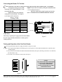
Wiring Table
Wiegand
Clock & Data
+DC
+DC
Red
Ground
Ground
Black
---
Card Present
Orange
Data 0
Data
Green
Data 1
Strobe/ Clock
White
Shield Ground
Shield Ground
Drain
HID CORPORATION
RED - 4.75VDC TO 16VDC
BLACK - GROUND
ORANGE - CARD PRESENT
GREEN - DATA 0/DATA
WHITE - DATA 1/CLOCK
DRAIN - SHIELD GROUND
Cable Notes
When using a separate power supply for the ProxPoint Reader,
the power supply and Host should have a common ground
(voltage reference).
Figure 2
Testing and Operation of the ProxPoint Reader
A
fter wiring the Reader and power supply, the Reader is ready to be tested.
1. Power up the Reader and the LED flashes green to red to green to red. This indicates that the micro-controller unit is
working properly.
2. Present an ID card to the Reader and the LED should momentarily turn green, indicating a read of the card. After that,
the LED returns to red.
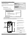
3. Secure the cover to the base as shown below in Figure 3.
NOTES:
THE ABOVE ARE RECOMMENDED
INSTALLATION PROCEDURES.
ALL LOCAL, STATE AND
NATIONAL ELECTRICAL CODES
TAKE PRECEDENCE.
Figure 3
HID Corporation 9292 Jeronimo Road Irvine, CA 92618-1905 USA TEL (949)598-1600 (800)237-7769 FAX (949) 598-1690
Web Page/e-mail: www.prox.com ProxPoint Reader Installation Manual 6005-900 Rev C
2 of 2