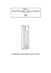
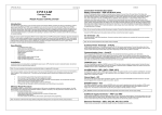
1
PR302LCDv2.0EN.doc
PR302LCD v2.0
ACCESS CONTROLLER WITH INTEGRATED
PROXIMITY & PIN READER
FIRMWARE VERSION 119.0
Installation Manual
1
PR302LCDv2.0EN.doc
General Description
The PR302LCD controller is dedicated for use in Access Control and Time & Attendance systems. It may be configured to perform both
function simultaneously or exclusively. PR302LCD has a built-in proximity reader, 12 digit metal keypad and LCD display. Controller offers
three inputs, one relay output and two transistor outputs. Inputs and outputs can be configured to several pre-defined functions. PR302LCD
can register up to 4000 users, every user can be identify by Card, PIN or both method together (Card+PIN). The reader which is build-in into
controller accepts UNIQUE standard cards (EM4001/2 or compatible). Controller offers In Circuit Programming feature which enables
firmware downloading into microprocessor memory. PR302LCD may operate with one external identification terminal (PRT series terminal
or Wiegand interface reader). Usually an remote identification terminal is used when door has to be controlled on both side or when
controller has to be located in protected area (room) in order to avoid access of unauthorized person to controller’s electronic circuit.
PR302LCD may activate door lock through internal relay output (REL1) or through relay output located on XM-2 remote I/O expander.
Because an XM-2 module can be installed in remote, secure location the use of XM-2 expander increase overall controller’s security level
significantly. PR302LCD may operate is autonomic mode or in networked system equipped with CPR control panel or without it. Due to
complex and wide range of settings which can be defined in controller PR302LCD can not be programmed manually, it can be downloaded
from PC computer only. Programming from PC requires UT-2 communication interface.
PR302LCD features
!
!
!
!
!
!
!
!
!
!
!
!
!
!
!
!
!
!
!
!
!
!
!
!
!
!
!
!
!
!
!
!
!
!
!
!
!
!
!
!
!
!
!
!
!
!
Single door, dual side, access controller with integrated RFID/PIN reader.
Autonomic or networked operation.
Card and/or PIN identification.
Card usage limit definition.
Card time period limit definition.
4000 users.
250 access groups.
500 access zones.
99 general purpose time schedules.
Holiday schedules.
Non violate 32 000 event buffer.
Real Time Clock.
2 x 16 Char LCD display with backlight.
Three multipurpose NO/NC inputs.
Two multipurpose, electronically protected 1A transistor outputs.
One relay output (form C contacts, 1.5A rated).
Door lock controlled by internal relay output or by remote secure relay module (XM-2).
Inputs/Outputs controlled by time schedules.
Four user types: Normal, Swicher full, Switcher limited and Master.
Door contact, Exit button, Forced entry, Duress and more function.
Soft or Hard mode anti-passback with reset schedule.
Special door lock modes: Normal, Locked, Unlocked and Conditional Unlocked.
Card or PIN and Card+PIN, identification modes, each under schedule control.
Special entry modes; Card+Card and Conditional Access, both under schedule control.
High Security identification mode (requires additional reader e.g. biometric).
Customer defined T&A registration modes.
T&A registration modes controlled manually from keypad, by external line or by schedule.
Integration with IAS (Intruder Alarm System) through dedicated output line.
Intruder Detector Input with automatic Arming/Disarming feature.
Capable to operate with one remote identification terminal (reader).
PRT (Roger) series and Wiegand 26/34/42/66 bit reader support.
XM-2 remote I/O expander support.
PSAM-1 power supply alarm module support.
XM-8 lift access control module support.
Biometric reader support.
Firmware upgrade available.
Metal case and keypad.
RS485 interface.
12VDC/120mA supply.
Accepts UNIQUE (EM4001/2) cards.
7 cm reading range for ISO card.
Windows 95/98//NT/ME/2K/XP software, license free for systems up to 8 doors.
Programming via PC, manual programming not available.
Transactional method of programming.
Comply with EN 50133-4.
CE mark.
Functional Description
Autonomic operation
In autonomic (standalone) mode after configuration procedure controller may continue operation and does not need to communicate with
any other equipment, events are recorded and stored in its internal memory banks, internal clock circuit control time schedules and access
levels. The connection to computer is required only when system operator intend to change controller’s settings or when contents of
controller’s event buffer has to be downloaded to access system database.
Networked operation with CPR
When controller operates in networked system together with other controllers and CPR control panel, events are continuously transferred
from all controllers to CPR’s internal buffer. When connection with CPR is broken controllers automatically move to autonomic mode and
store events in theirs internal memory banks, after communication with CPR is restored controllers return automatically to networked mode,
in both cases controllers retain theirs full functionality (no functionality is lost or reduced). During normal system operation CPR synchronize
real time clocks of all controllers and stores events which occurred in system. Events stored in CPR and eventually in controllers’ buffers can
2
PR302LCDv2.0EN.doc
be manually downloaded to PC database or will be downloaded automatically anytime the Monitoring window of PR Master program is
activated.
Note: The main advantage of networked system equipped with CPR is that events which have been occurred on controllers are instantly
transferred to remote “secure” buffer in CPR and that CPR continuously synchronize clocks on all controllers so even after long time period
controllers’ clocks have the same time and events registered in system have perfect chronology.
Networked operation without CPR
When computer is connected to access control system and Monitoring window of PR Master is active, events are continuously transferred
from controllers to PC database. When PR Master operate with monitoring window deactivated controllers move to autonomic mode and
save events in theirs internal buffers. Events stored in buffers can be later transferred to PC using interactive command or will be
downloaded automatically anytime monitoring window is started.
Note: Controller automatically detect a HOST device (CPR control panel or PR Master running in monitoring mode) and move automatically
to networked mode and vice verso, when no HOST is detected on communication bus (system is not equipped with CPR or PR Master
operates without monitoring window) controllers move to autonomic mode.
Single Door Operation
Each model of PRxx2 series controller may operate with two identification access points (access terminals), first located on EXIT side and
second located on ENTRY side of the controlled door. As a default an EXIT terminal has assigned address ID=1 where ENTRY terminal has
assigned address ID=0. The PR302 and PR302LCD controllers offer one terminal build-in into theirs electronic circuit, this terminal is treated
as an EXIT terminal ID=1, an ENTRY terminal ID=0 may be connected to controller’s Clock and Data lines. A default address assignments
for ENTRY and EXIT terminals may be changed by option Terminal ID=1 located on ENTRY, in this case terminal ID=0 is treated as EXIT
point and terminal ID=1 as ENTRY point. Generally ENTRY/EXIT assignments described above refer to anti-passback function only, this
function determines actual status of users which may have status as logged on ENTRY, logged on EXIT or UNKNOWN.
Note: There are at least three occasions listed below when ENTRY and EXIT terms are used:
•
•
ENTRY/EXIT terms which refers to entry and exit terminal which control door on both sides,
ENTRY/EXIT terms which refers to entry and exit access points which define Attendance Area used in statistic
calculations (Users Attendance Statistic),
ENTRY/EXIT terms which refers to T&A Modes of identification point.
•
In each listed above case ENTRY/EXIT terms refer to another physical or logical matter, for example at the same time an access terminal
may have ENTRY status for anti-passback function, EXIT status for particular Attendance Area calculation and may have assigned EXIT
mode for T&A.
RS485 Communication interface
Controller is equipped with RS485 serial communication interface which is dedicated for communication with PC computer and optional CPR
control panel, up to 32 controllers may be connected to one RS485 communication bus. Each controller connected to communication bus
must have individual address (ID number) from 00 to 99. The PR Master v4.x supervising program enables up to 10 separate networks to be
connected to one computer. Each network requires UT-2 communication interface which converts RS232 signals into RS485 standard. The
access network or even separate controller can be also connected to PC through computer network, this requires UT-4 communication
interface. The UT-4 acts as communication converter between TCP/IP network and RS485 serial interface.
Clock & Data interface
Controller is equipped with Clock and Data interface which is dedicated for connection with remote reader(s) and/or extension modules.
PR302LCD may operate with following external readers and modules:
-
PRT Card/PIN reader,
PRT User ID reader,
Wiegand 26/34/42/66 bit PIN reader,
Wiegand 26/34/42/66 bit Card reader,
Wiegand 26/34/42/66 bit User ID reader,
XM-2 input/output remote module,
XM-8 lift access control module(s),
PSAM-1 power supply alarm module,
High Security PRT series terminal or Wiegand interface reader.
Each PRT reader or extension module connected to Clock and Data interface must have its individual address (ID number) from 0 to 15. The
following assignments for addresses are valid:
Address
(ID number)
Device
0
PRT reader
1
Reserved
2
3
PRT reader
PRT reader
PSAM-1
module
XM-2 module
Reserved
Reserved
XM-8 module
XM-8 module
4
5
6
7
8
9
Notes
External reader, logically interpreted as ENTRY reader, optionally
may be set as EXIT reader.
The reader build-in into controller is logically interpreted as EXIT
reader, optionally may be set as ENTRY reader.
The High Security reader on ENTRY.
The High Security reader on EXIT.
Power supply alarm module, optional part of PS20 (Roger) power
supply.
The 2 inputs and 2 relay outputs expander module.
The lift control module, floors 1-8.
The lift control module, floors 9-16.
3
PR302LCDv2.0EN.doc
10
11
12
13
14
15
Reserved
Reserved
Reserved
Reserved
Reserved
Reserved
Note: If controller is configured for operation with remote Wiegand type reader instead of PRT terminal no XM modules nor PSAM-1 can be
connected to Clock and Data lines simultaneously.
Input Lines
Controller offer three input lines: IN1, IN2 and IN3. Each input can be programmed as NO or NC type. The function of each input can be
assigned during controller’s setup. The following input functions are available:
Function
Description
Input ignored
Selecting this function will disable decoding of this input, function can be used for temporary input
deactivation without disconnecting it from triggering source.
Door Contact
Input is dedicated for contact which will indicate that door is open. Input activation generate [Door
opened] event, input deactivation generate [Door closed] event.
Exit Button
Input is dedicated for operation with button which will be used to open the door without use of any
identifier. Activation of this input will activate door lock for the same time period as after standard
[Access granted] event, function is usually used for Request To Exit (REX) button connection.
Activation/deactivation of input generate [Exit button ON]/[ Exit button OFF event].
[ON/OFF] Mode Control
Input is dedicated for operation with some button, switch or output line which will control actual
[ON/OFF] mode of controller. Activation of this input force controller to [ON] mode, as long as input
is triggered controller will remain in [ON] mode. Only one input on controller can be configured to
this function. When such a function is selected any other methods of [ON/OFF] mode control will be
forbidden.
AC Lost Input
Input is dedicated to be connected to output line or contact which will indicate that AC supply of
power supply unit is lost. Some brands of power supply are equipped with such a output line (e.g.
PS20N from Roger). After input line is triggered controller generate [AC lost alarm ON] event, when
line returns to normal condition controller generates [AC lost alarm OFF] event.
Low Battery Input
Input is dedicated to be connected to output line or contact which will indicate that reserve battery is
in low condition. Some brands of modern power supply are equipped with such a output line (e.g.
PS20N from Roger). After input line is triggered controller generate [Low battery alarm input ON]
event, when line returns to normal condition controller generates [Low battery alarm input OFF]
event.
Bell Button Input
Input is dedicated to be connected to button which will indicate that somebody want to enter
premises. After input is triggered controller generate [BELL button ON] event and optionally may
activate output line if configured as [BELL Output], when line returns to normal condition controller
generates [BELL button OFF] event and clears [BELL Output] line.
Tamper Loop Input
Input is dedicated to be connected to tamper contact which will indicate that unauthorized person
try to open controller/terminal case. After input is triggered controller generates [Tamper loop ON]
event, when line returns to normal condition controller generates [Tamper loop OFF] event.
Intruder Detector Input
Input is dedicated to be connected to some kind of intruder detector (e.g. PIR) which will indicate
intruder’s attendance in premises. After input is triggered controller generates [Intruder detector
ON] event, when line returns to normal condition controller generates [Intruder detector OFF] event.
The intruder detector input line can by bypassed in [ON] mode, this can be achieved selecting
[Disable Intruder detector when controller in ON mode] option.
[ON/OFF] Mode Reversing Input
Input is dedicated to be connected to button (or output) which when changes condition will alternate
[ON/OFF] mode of controller to opposite condition (from [ON] to [OFF] or reversely). Each time this
type of input is triggered controller changes [ON/OFF] mode.
Access Disabling Input
Input is dedicated to be connected to switch (or output) which when activated will disable access to
controlled door, activation/deactivation of this input generate [Access disabled input ON]/ [Access
disabled input OFF] event.
Stable T&A Mode Setting Input
Input is dedicated to be connected to some kind of button which when pressed will change the
actual T&A Mode of controller. Each time input is triggered controller move to next predefined T&A
Mode. After new T&A Mode is set controller remains in selected T&A Mode till next time button is
pressed or till [T&A Mode Schedule] will change actual T&A Mode.
Momentary T&A Mode Setting
Input
Input is dedicated to be connected to button which when pressed will change the T&A Mode of
controller. Every time input is triggered controller move to next predefined T&A Mode and then
waits for identifier, as soon as identifier (Card/PIN) is entered controller returns to its previous T&A
Mode, when no identifier is read during 8 seconds period controller returns to its previous T&A
Mode automatically.
Selects Predefined T&A Mode –
Stable Type Selection
Input is dedicated to be connected to button which when pressed will turn controller to specified
T&A Mode. The T&A Mode which will be set after input is triggered is declared by installer for every
input line individually. The new T&A Mode is set for undefined time (until next command which will
change T&A Mode of controller).
Selects Predefined T&A Mode –
Momentary Type Selection
Input is dedicated to be connected to button which when pressed will turn controller to specified
T&A Mode. The T&A mode which will be set after input is triggered is declared by installer for each
input line individually. The new T&A Mode is active till nearest user identification, if during next 8
seconds no identification was performed controller return to previously selected T&A Mode.
4
PR302LCDv2.0EN.doc
APB Reset Input
Input is dedicated to be connected to button which when pressed will reset APB Register of
controller. Any time input is activated an internal APB Register of controller is initialized (cleared)
and [APB Reset] event is generated.
Clears all outputs on XM-8
elevator control module
Input is dedicated to be connected to output line (contact) which when triggered will clear all outputs
on XM-8 elevator control module(s).
Sets all outputs on XM-8
elevator control module
Input is dedicated to be connected to output line (contact) which when triggered will set all outputs
on XM-8 elevator control module(s).
Besides those listed above functions input lines can be configured to customer defined input functions. Using PC software installer may
define new input line functions, definition of input line function consist from function name and function code. Function name can be used to
distinguish purpose of input e.g. [Guard Tour Button], [Alarm Button], [Assistance Request Button], each time input is activated system will
register events which consist from function name and ON or OFF status which specify if the input line was activated or deactivated. The
activity of each input can be controller by time schedule.
Output lines
Controller offer two transistor outputs (IO1 and IO2) and one relay output (REL1). The relay output is assigned to control door lock, the
functions of IO1 and IO2 can be assigned during controller’s setup. The activity of each output can be controlled by time schedule, when
schedule disables output it move to deactivated condition. The following output functions are available:
Function
Description
Alarm Output
Output is activated when at least one alarm situation occur. There are three different alarm situation
which can be signalized on this output: [PREALARM], [DOOR ALARM] and [FORCED ENTRY].
Installer may select which alarm output should output line signalize.
General Purpose Output
Output is activated through interactive command which can be send from PC.
Activated when controller in
[ON] mode
Output is activated when controller turns to [ON] mode and remain active as long as controller
remain in this mode.
Activated on [Access granted]
event
Output is activated after controller grant access and remains in active state until door contact
indicate that door became closed or lock activation time period has elapsed.
Activated on [Door open] event
Output is activated after controller detects that door became open and remains active as long as
door is being open.
Activated on [Access denied]
event
Output is activated for period abut 2 seconds after controller denies access.
Activated by schedule
Output is activated/deactivated according to selected schedule, no other method may change
condition of output line.
Activated by schedule or PC
command
Output is activated/deactivated according to selected schedule or interactive command from PC,
both control methods have the same priority.
Activated when identification on
terminal ID=0
Each time a successful identification is made on EXIT terminal (ID=0) output go to active condition
and remains in this state till successful identification on ENTRY terminal (ID=1) is performed.
Usually this option is used when controller operates with TRIPOD type gate where lock must be set
for clockwise or anticlockwise rotation depending on which terminals identification has been carried
out.
BELL Output
Output is triggered when controller recognize [BELL Input] activation and remains active as long as
[BELL Input] remains triggered. This output may be also triggered by BELL Button key which is
available on PRT42 and PRT42-BK access terminals.
Activated when at least one user
logged into premises
Output is activated when at least one user is logged inside premises, output returns to non-active
condition when all users have left premises or when anti-passback reset occur.
Activated when max. logged
user limit reached
Output is activated when the number of users logged into premises have reached maximum value,
output returns to non-active state when the number of users is less then maximum allowed value or
when anti-passback reset occur.
Alarm Output
In most cases one output line of controller is configured as [Alarm Output] and is dedicated to trigger signaling device when alarm situation
occur. The [Alarm Output] line may be configured to signalize the following alarms:
Alarm name
Description
Priority
Signalization method
PREALARM
The alarm occurs after three consecutive
attempts of entering an unknown identifier
repeated in a period shorter than 1 minute.
Low
Single pulse every 2 seconds.
DOOR ALARM
The alarm occurs after door remains open in a
period of time defined by “Time for door
closing”.
Middle
Double pulse every 2 seconds.
FORCED ENTRY
The alarm occurs after door opening without
the use of controller.
Highest
Pulse/Pause 0.5/0.5 sec.
Signalization of the PREALARM, DOOR ALARM and FORCED ENTRY disappears automatically after 3 minutes or can be switched off
earlier by using any valid identifier (Card/PIN) registered in system. Alarm on controller can also be cleared remotely from PC. When the
[ALARM Output] has been programmed to signalize more than one alarm condition, only the highest priority alarm is signalized.
Relay output (REL1)
The REL1 relay output is dedicated to control door lock. Each time controller grants access this output is activated for predefined period
declared in Lock activation time. Lock activation time can be set from 1 to 255 seconds or minutes or for undefined period, in last case
5
PR302LCDv2.0EN.doc
installer must select Bistable mode option. When Bistable mode is selected each time access is granted REL1 output moves to reverse
condition (from ON to OFF or inversely). When Auto-relock option is set, door lock is activated until door contact connected to controller will
indicate that door became open, never the less REL1 will not be triggered longer then period defined in Lock activation time. Lock
activation can be temporary disabled when controller stay in OFF mode, this can be achieved by Access disabled in [OFF] mode option.
This feature is usually used when some of controller output line is dedicated to Arm/Disarm alarm zone or intruder detector. In this case
switching controller to OFF mode will arm alarm system (or alarm zone) and thus will automatically disable access to controlled area for all
users regardless of actual access settings.
Users
Controller distinguish the following five types of users:
USER TYPE
ID NUMBER
AUTHORIZATION
INSTALLER
NONE
Authorization for an entry to the installer programming mode, he has not assigned any identification
number.
MASTER
0
Authorization for an entry to the user programming mode, opening the door and switching the
controller between the ON and OFF modes, he has identification number ID=000.
SWITCHER
Full
001..049
Users with ID = 001..049 have authorization for door opening and switching controller between the
ON an OFF mode.
SWITCHER Limited
050..099
Users with ID = 050..099 have authorization for switching controller between the ON and OFF mode
only, they have no authorization for door opening.
NORMAL
100..3999
Authorization only for door opening, users of this type have ID numbers from 100 to 3999. Optionally
users with ID 1000-3999 can be individually set as SWITCHER on particular controllers.
Note: Installer may define some users from ID=1000 to ID=3999 as Local SWITCHER type, such a setting can be done individually on each
controller operating in access system. As a result some user(s) may be a SWITCHER type on some particular controller but the NORMAL
type on other ones.
PR302LCD identifies users by his/her identifier, each user has his/her own identification number (ID = 0000…3999). Identifier can be a PIN
or Card . In case the Card+PIN mode is active, controller requires use of both forms of identification (PIN and Card) in any sequence (Card
then PIN or reverse sequence). PR302LCD accepts PINs consisting from 3 up to 6 digits and Cards (proximity transponders) based on the
V4001/2 module from EM MICROELECTRONIC – MARIN Switzerland.
Proximity Card specification:
•
64-bit ROM memory, pre-programmed by the manufacturer.
•
Amplitude modulation ASK (MANCHESTER coded).
•
Operating frequency 125 kHz.
•
Transmission speed 2kB/sec.
Note: The term "identifier" or "Ident." means the operation which consist from Card reading and/or PIN entry (sequence no matter).
Examples:
1.
[Identifier] = [PIN][#]+[Card]
2.
[Identifier] = [Card]+[PIN][#]
3.
[Identifier] = [PIN] [#]
4.
[Identifier] = [Card]
or
or
or
Examples [1] and [2] refer to situation when option Card+PIN is active.
Duress entry.
If the user enters his/her PIN code, which differs from its original form by “one” (plus or minus), controller interprets it as a duress code entry.
When duress entry is recognized the DURESS event is generated and FORCED ENTRY alarm signalization might occur on output line.
Example
The original code is [4569], entering [4568][#] or [4560][#] is treated as a duress entry.
Note: For proper recognition of duress entry, the PIN codes of individual users should differ one from each other at least by a value of +/- [2]
on the last significant digit.
The detection of duress codes can be disabled from managing software.
ON/OFF Mode of Controller
PR302LCD controller may stay in ON or OFF mode, both modes are signalized on bi-color LED marked ON/OFF. The current mode (ON or
OFF) of controller may be optionally signalized on dedicated output line (output option: Activated when controller in [ON] mode), when
controller is switched from ON to OFF mode (or in reverse direction) output line will follow this changes. Generally the ON/OFF modes are
dedicated for auxiliary control purposes e.g. light control, copy machine control etc. but in most cases they are used for integration with
Intruder Alarm System (IAS). Connecting controller’s output line which follows ON/OFF mode to adequate input line of Intruder Alarm Panel
user may arm or disarm entire alarm system or particular alarm zone, in this case when controller goes to OFF mode (ON/OFF LED set to
red) this will automatically arm adequate alarm zone and vice verso when controller goes to ON mode (ON/OFF LED set to green) this will
automatically disarm adequate alarm zone. The access to premises/zone can be temporary blocked when controller stay in OFF mode, this
can be achieved by option Access disabled in OFF mode.
An ON/OFF mode of controller can be controlled in few listed below ways:
•
•
manually by SWITCHER or MASTER user,
by external input line configured as ON/OFF Mode Control Input or ON/OFF Mode Reversing Input,
6
PR302LCDv2.0EN.doc
•
•
automatically by ON/OFF Mode Schedule,
remotely by interactive command from PC (Set controller to ON (OFF) mode).
Note: When ON/OFF mode is controlled by ON/OFF Mode Control Input all other methods of ON/OFF mode control is forbidden.
Manual method of ON/OFF mode control
Controller can be manually switched between ON and OFF modes by SWITCHER or MASTER type users. The manual switching between
ON and OFF modes can be performed only when adequate time schedule (SWITCHER Schedule) enables this type of operation.
The following ON/OFF mode manual switching procedures are allowed:
Procedure for MASTER or SWITCHER FULL users: enter MASTER or SWITCHER FULL identifier first time (Card and/or PIN depending on
actual valid identification mode), wait till LED SYSTEM starts flashing, when LED SYSTEM is flashing enter the same identifier second time,
controller will change ON/OFF mode. After first use of MASTER or SWITCHER identifier controller may or may not activate door relay, it
depends on actual access settings. When option If access denied SWITCHER disabled is active controller will not change ON/OFF mode
when MASTER or SWITCHER user which performed identification has not access authorization at that particular moment of time.
Procedure for SWITCHER LIMITED users: enter SWITCHER LIMITED identifier once (Card and/or PIN depending on actual valid
identification mode) controller will change ON/OFF mode immediately, door lock will not be activated.
Anti-passback (APB)
When anti-passback function is activated users are obliged to perform identification alternatively on ENTRY and EXIT access points. The
anti-passback can be used in two variants:
•
•
APB Hard (anti-passback hard)
APB Soft (anti-passback soft)
When APB Hard is selected, the attempt to use the same identifier two consecutive times on the same ENTRY or EXIT point will be
rejected, access will be denied and Anti-passback violation event will occur, when APB Soft is selected an attempt to use the same
identifier on the same ENTRY/EXIT point will be accepted but Anti-passback violation event will be generated. The activity of antipassback can be reset (initialized) periodically according to APB Reset Schedule or manually triggering APB Reset Input line. After APB
Reset the first use of each identifier can be performed on ENTRY or EXIT terminal, but after this first identification user must use its identifier
alternatively on ENTRY and EXIT terminal.
Identification Modes
Controller enables identification of users in two different modes:
Identification
Mode
Card/PIN
Card+PIN
Description
Controller requires Card or PIN to be entered for successful identification.
Controller requires Card and PIN to be entered for successful identification, no matter what sequence Card then PIN
or PIN then Card.
Installer may define Default Identification Mode of controller which specify identification method which will be required for each type of
users (Master, Switcher and Normal), Default Identification Mode is set separately for each type of users. In some periods of day or week
controller can be switched to Card+PIN mode according to Card+PIN Schedule. This schedule specify time periods when all types of users
must use Card+PIN method. There are two predefined schedules which can be set for Card+PIN Schedule: Always and Never. When
Always schedule is selected controller will always require Card and PIN, when Never schedule is selected, controller will always stay in
Default Identification Mode.
Card+Card Mode (Dual Card)
When this mode is active controller requires two users two perform successful identification then access might be granted. This mode can be
controlled by Card+Card Schedule, selecting schedule Never will permanently disable this mode where schedule Always will permanently
activate it. When together with Card+Card option the Card+PIN mode is active both users must read his/her Card and enter his/her PIN
otherwise identification will not be successful.
High Security Mode
When this mode is active users must perform two steps identification procedure, a standard identification (Card/PIN or Card+PIN depending
on actual valid identification mode) plus an additional identification on High Security reader. The High Security reader can be connected to
the same Clock & Data lines which are used for communication with access terminal and/or extension modules. Controller accept few types
of High Security readers including Wiegand Card/PIN and WIegandt User ID. The Wiegand Card/PIN sends the code of entered PIN or
Card, the Wiegand User ID sends ID number of user which has made identification. The High Security option can be set individually for each
side of door and can be controlled by time schedule. Generally, the High Security option is dedicated for those doors which have to be
protected with advanced identification method (e.g. biometric identification) .
Door Modes
Door Mode determines how the controller will energize and de-energize door lock. Door lock can be set to few listed below modes of
operation:
Door Mode
Normal
Unlocked
Conditional Unlocked
Locked
Description
Door lock is activated after controller decide to grant access.
Door lock is continuously energized, door can be opened by any unauthorized person.
Initially door lock is not energized, but when first authorized person come and use its identifier lock became
energized and remain in this state until new door mode is set.
Activation of door lock is permanently forbidden, no matter if some user has authorization for access or not,
every attempt to open the lock will be rejected.
7
PR302LCDv2.0EN.doc
As a default door lock stay in Normal Mode but it can be switch to another mode by Door Mode Schedule or by remote command from PC.
Operation with XM-8 module
The PR302LCD may operate with one or two remote XM-8 I/O dedicated for lift access expanders. Both modules are connected to controller
via Clock and Data lines. The first one (address ID=8) is assigned to control access to floor 1-8, where the second one (address ID=9)
controls access to floors 9-16. Each time a successful identification is made controller activate predefined set of XM-8’s relays, relays
remain active until input line assigned to option : Clears all outputs on XM-8 elevator control module(s) is triggered or until next
identification is accomplished and new set of outputs is activated. The operation with XM-8 module(s) is activated through option: Enable
XM-8 elevator control module(s). Alternately all outputs of XM-8 can be activated by input line programmed to option: Sets all outputs on
XM-8 elevator control module(s).
Operation with XM-2 module
Controller may operate with one external XM-2 I/O module (address ID=5) dedicated for remote input and output extension. The XM-2
module is connected to controller via Clock and Data lines. The XM-2 offers two relay outputs (REL1 and REL2) and two NO/NC inputs (IN1
and IN2). The REL1 output on XM-2 is activated/deactivated simultaneously with REL1 output of controller, the second XM-2’s output
(REL2) is activated/deactivated simultaneously with controller’s IO2 output. The XM-2’s inputs are normally ignored but when allowed during
controller’s setup they can be used instead of IN1/IN2 inputs located on controller board. Installer may select which input(s) (controller’s or
XM-2’s) should be used by controller. Generally XM-2 module is dedicated for PR302/PR302LCD controllers which normally activate door
lock through internal relay, this relay can be easy accessed by non authorized person. When XM-2 is used, door lock may be activated not
by internal controller’s relay but by remote relay output located in secure location, this increase overall controller’s security level significantly.
The operation with XM-8 module(s) is activated through option: Enable XM-2 remote I/O expander module. There are two additional XM-2
options:
•
Ignore IN1 on controller, enable IN1 on XM-2 – controller will use remote (on XM-2) IN1 input instead of local (on controller) IN1,
remote IN1 input will have the same function as assigned previously for local IN1 input, the electrical signals on controller’s IN1
line will be ignored.
•
Ignore IN2 on controller, enable IN2 on XM-2 – controller will use remote (on XM-2) IN2 input instead of local (on controller) IN2,
remote IN2 input will have the same function as assigned previously for local IN2 input, the electrical signals on controller’s IN2
line will be ignored.
Operation with PSAM-1 module
Controller may operate with one PSAM-1 power supply alarm module (address ID=4) connected to controller through Clock and Data lines.
The PSAM-1 is an optional part of PS20 power supply offered by Roger, it delivers following data:
•
actual power supply DC output level,
•
low battery alert
•
battery failure alert
Note: PSAM-1 may operate in autonomic or networked mode, when connected to controller’s Clock and Data lines it should be configured to
networked mode with address ID=4.
The operation with PSAM-1 module is activated through option: Enable PSAM-1 power supply alarm module.
Operation with Wiegand readers
Controller may operate with one Wiegand interface reader connected to Clock and Data lines instead of standard PRT terminal with address
ID=0. Controller accept 26, 34, 42 and 66 bit Wiegand transmissions. The transmission of Wiegand reader can be interpret by controller as
PIN, Card or User ID number. When controller is configured for operation with Wiegand User ID reader it interprets transmitted digits as ID
number of user which has performed identification, when is set to Wiegand PIN reader controller interprets transmitted digits as PIN number,
when is set to Wiegand Card reader controller interprets transmitted digits as Card number. The Wiegand User ID mode is generally
dedicated for biometric type readers which does not transmits PINs nor Card’s codes but deliver ID number of user which has made
successful identification. When controller is configured to Wiegand type reader no other extensions modules (XM-2, XM-8 or PSAM1) nor
standard PRT reader can be connected simultaneously to controller’s Clock and Data lines. As default Wiegand reader connected to Clock
and Data lines is logically interpreted as an ENTRY terminal ID=0.
T&A Registration
The PR302LCD offers T&A registration which further can be used for calculation of total job hours. Each Access granted event which occur
on controller has assigned a T&A Mark (T&A status) which specifies what kind of entry/exit has been registered. The actual type of
registration for T&A purposes is determined by controller’s T&A Mode. PR302LCD offers few predefined T&A Modes (Entry, Exit, On Duty
Exit or Ignored for T&A) as well as customer defined. Each T&A Mode has its individual ID number from 0 to 255, numbers between 0 and
50 are reserved for predefined T&A Modes which can not be modified or changed. When controller stay in Ignored for T&A mode it means
that events which will occur during this mode will not play any rule in T&A reports or calculations. The customer defined modes can be useful
when new types of entry/exit are requested for detailed statistics of users attendance. In RACS system each access point
(controller/terminal) may have its own Default T&A Mode. The T&A Mode of access terminal can not be dynamically changed during system
activity except situation when option Terminals ID=0 and ID=1 have the same T&A Mode is set, the T&A Mode of controller(s) can be
dynamically changed in few manners which are listed below:
•
•
•
by adequate Time Schedule (T&A Mode Schedule),
by manual command entered from controller's keypad,
by activation of input line.
If option Terminals ID=0 and ID=1 have the same T&A Mode is active events registered on terminal ID=0 have the same T&A status a as
events registered on terminal ID=1 (no matter if event was registered on terminal ID=1 or ID=0 they have assigned the same T&A status
which is actually assigned for terminal ID=1). Generally, this option is dedicated to situation when controller is integrated into system which
utilize another card standard (e.g. HID, Mifare), in such a configuration T&A Mode might be changed on controller (using keypad, input line
or time schedule) but identification will be performed on remote Wiegand interface reader connected to Clock and Data lines.
Note: The current (actual valid) T&A Mode of controller and actual time/date is continuously presented on controller’s LCD display.
8
PR302LCDv2.0EN.doc
Setting T&A Mode from keypad
Installer may enable/disable dynamic setting of T&A Mode from controller's keypad. When manual T&A Mode setting from keypad is enabled
it may or may not require a special password which will protect from unauthorized change of T&A Mode. The manual change of T&A Mode
can be set for a limited period (momentary change) or for unlimited time (stable change). When using “momentary change” method the
newly selected T&A Mode will be valid for nearest Access granted event only, when “stable method” is used all Access granted events
which will occur during selected T&A Mode will have the same (new) T&A mark. There are following keypad shortcuts which enable change
of T&A Mode of controller:
[*][#][*][#].....[*][#]<Password>[#]
This command enables stable (for unlimited period) change of T&A Mode, each time the [*][#] sequence is entered controller move to next
available (defined in PR Master software) T&A Mode. After last [*][#] sequence controller remain in T&A Mode. The sequence
<Password>[#] is obligatory only if the relevant password was defined.
[*][1][S][T][U][#]<Password>[#]
This command enables momentary (until next Card/PIN entry) change of T&A Mode. The [S][T][U] digits specify the ID code of required T&A
Mode. When Card/PIN is entered and [Access granted] event occur it will be registered with T&A status which is actually presented on LCD
display, after this controller restores previous T&A Mode. If during 8 seconds period no [Access granted] events occur controller will turn to
previous T&A Mode. The sequence <Password>[#] is optional and is required only if relevant password was defined.
[*][3][S][T][U][#]<Password>[#]
This command enables stable (for unlimited period) change of T&A Mode. The [S][T][U] digits specify the ID code of required T&A Mode. All
[Access granted] events which will occur during new T&A Mode will be registered with T&A status which is actually presented on LCD
display. The sequence <Password>[#] is optional and is required only if the relevant password was defined.
[*][1][255][#]<Password>[#]
This function switch controller to its Default T&A Mode.
Setting T&A Mode from input
Installer may define one or more input line to be used for setting required T&A Mode of controller. The input line can be used to set specified
T&A Mode or to switch controller between different T&A modes. The input line which dynamically change T&A Mode is very useful especially
when an external button(s) is required to select specified T&A Mode. There are following input function which enable setting of T&A mode
from external button:
Stable T&A Mode setting input
When this type of input line is triggered controller move to next predefined T&A Mode and remain in this mode until next command comes
and change it again.
Momentary T&A Mode setting input
When this type of input line is triggered controller move to next predefined T&A Mode and remain in this mode until next Card/PIN is entered,
after this controller returns to previous T&A Mode. When no Car/PIN is entered during 8 seconds period controller will restore previous T&A
Mode automatically.
Predefined T&A Mode setting input
When this type of input line is triggered controller move to dedicated T&A Mode and remain in that mode until next command comes and
change it again. Each input line can be used for setting individual T&A Mode. For example IN1 can be used to set “Exit”, IN2 can be used to
set “Entry” and IN3 to set “On Duty Exit”.
T&A Mode controlled by schedule
The T&A Mode Schedule enables automatic change of controller T&A Mode according to defined time schedule details. The T&A Mode
Schedule specifies what T&A Mode will be set on controller in particular moments of day, week or holydays.
Note: All listed above methods of T&A Mode control may be used simultaneously to switch controller between different T&A Modes.
Holidays
Holidays definition specify some days during year period in which controller behavior is different as usual. Installer can define some special
rules for holidays, PR Master software enables four types of holidays settings to be defined, H1, H2, H3 and H4. The holiday definition
consist from:
name of holiday day, (e.g. Easter)
date of holiday, (e.g. 12 of April)
detail settings of holiday (e.g. H1)
Signalization
Optical (LED) signalization
Controller offer three LEDs marked as ON/OFF, OPEN and SYSTEM. An ON/OFF led is a bicolor type and may be set to green or red.
When set to green it signalize that controller is in ON mode, when is set to red it signalize that controller is in OFF mode. Led OPEN (green)
signalize that relay output is activated what usually mean that door lock is energized. A SYSTEM led (amber) is activated for a moment
each time a card or PIN is read, it pulses continuously after SWITCHER FULL, SWITCHER LOCAL or MASTER identifier is used and
controller wait for next part of command which will change ON/OFF mode of controller.
Note: When all three leds are blinking and a short acoustic beep is generated periodically it means that controller memory is corrupt and
MEMORY RESET is required.
Acoustic signalization
The following acoustic signals can be generated by controller:
9
PR302LCDv2.0EN.doc
Signal
Description
One beep
Card read or Key pressed.
Three beeps
OK signal, command or operation finished successfully.
Two beeps
OK signal, controller wait for next part of command.
One long signal
Card or PIN unknown (nor registered in controller).
Two long signals
Card or PIN without authorization for entry (identifier registered in
controller’s memory but actually have no authorization for access).
Long signal repeated continuously
Memory contents corrupted, controller should be reprogrammed.
LCD Display
Generally the LCD display is dedicated to present some important information for system user. The LCD display offer two 16-characters
lines. The upper line presents the actual date and time where the lower line show the actual T&A Mode. For example:
CPR:
T &A :
1 2 / 01
EXI T
15: 31
Where:
“CPR” means that controller operates in networked mode with CPR access control panel or PC running in on-line monitoring, when
controller operates in autonomic mode it displays message “LOC” instead of “CPR”, the 12/01 is an actual date, the 15:31 is an actual time.
A “T&A:” message means “Actual T&A Registration Mode”, in this case “EXIT” means that all [Access Granted] events will be marked as
“EXIT” type.
Note: The controller time is automatically synchronized with clock settings of CPR Access Control Panel or with PC time. The
synchronization with PC time occur when PR Master operates in on-line monitoring mode only. The controllers’ clock can be set manually by
operator by means of interactive command send from PC.
Installation
Locate the controller in a dry area, all electrical connections must be made with power supply off. Once wiring is complete, power up the
control panel. The controller should be mounted using four mounting screws. Originally the new controller is delivered with preprogrammed
MASTER Card (included in carton box), preprogrammed MASTER PIN code (1234) and ID address set to “00“.
!
!
!
!
!
!
Avoid installing unit near big metal elements or on metal surfaces, this can significantly reduce reading range.
When installing unit on metal surface use optional non-metal spacer (10mm thick or more) between device and metal surface.
When controller and external terminal are supplied from another power source, both minuses (terminal’s and controller’s) must be
connected together.
Roger recommend to ground power supply minus.
Controller should not cause interferences to other equipment, however other devices can interfere with controller reader, avoid
locating controller close (<0.5m) to another reader or computer monitor, when an essential reading range reduction is observed
try to relocate units.
PR302LCD can not be mounted in external location, it hasn’t any protection against moisture, rain or cold, only indoor location are
acceptable.
Note: You must complete all wiring before applying DC supply to controller.
Connection Terminals Descriptions
Controller Supply, terminals: +12V PR302LCD should be supplied from 10.0 to 16.0V DC current source equipped with reserve battery. The average current consumption is
about 120 mA and may increase up to 170 mA when relay output is activated. Care must be taken when selecting cable diameter for supply,
installer must carefully calculate the maximum voltage dropout on supply lines which should not reach 1V in worst case, this is very
important especially when electric lock is supplied from the same supply source as controller and other electronic equipment. It is preferable
to use separate supply sources for electronic equipment and electric locks. When both elements are supplied from the same power source
they should be wired with separate cables. Usually the access control system is distributed on relatively large areas, this requires distributed
supply system with many supply sources located as close as possible to supplied equipment. It is recommended to use modern supply units
which are equipped with alarm output lines (AC Lost output and Low Battery output e.g. PS20). Such a lines should be connected to
controller inputs for continuous monitoring. Generally controller accepts linear and switched supplies types, occasionally poor quality of
switched supplies may generate some interferences on supply lines which may result in reduced card reading range, this may happen
especially when long range readers are installed, some brands of such readers are especially very sensitive to poor quality of supply.
Input lines, terminals: IN1, IN2 and IN3
Each controller input (IN1, IN2 and IN3) have the identical electrical structure. All inputs are NO/NC type with 5,6 kΩ resistor pulled up to
supply plus. During setup process installer may configure each input independent as NO or NC. The NO type input is triggered when
connecting it to supply minus. The NC input normally must be shorted with supply minus, when disconnecting it from supply minus it became
triggered. Controller ignore triggering impulses if they are shorter then 200 ms and accept signals that are longer then 500 ms. Detection of
signals between 200 and 500 ms is not guaranteed. Each controller input can be programmed to different function and may be under control
of time schedule.
RS485 communication interface, terminals: A, B and SHLD
The RS485 interface consist from two signal lines (A and B) and optional cable shield terminal (SHLD). Installer may use arbitrary
communication bus topology (star, three or any combination of both), no terminating resistors are required. In most cases communication
runs satisfactory on almost each types of cables (twisted/untwisted, shielded/unshielded) but it is not guaranteed in each case. Generally
unshielded, twisted type cables are preferred and guarantee best performance of communication. Each communication line (A and B) is
protected from voltage surges and from supply minus and plus. RS485 standard of transmission guarantee up to 1200 meters
communication distance with high immunity against interferences. When longer communication distances are required the UT-3 or UT-4
10
PR302LCDv2.0EN.doc
interfaces might be used. The one pair of UT-3 interfaces extend communication distance by 1200m, the UT-4 enables communication
trough computer network (LAN or WAN) witch utilize TCP/IP protocol.
Clock & Data interface, terminals: CLOCK and DATA
Each reader or module connected to Clock & Data lines must have its individual ID address which can be set on programming jumpers.
There are no restrictions for types of cables used for Clock & Data lines except that the maximum cable length may not exceed 150 meters
(500Ft.). The terminals or modules connected to Clock & Data lines should be supplied from the same supply source as controller, if not
supply minus of controller should be shorted with supply minus of other equipment which is connected to Clock & Data lines.
Tamper contact, terminals: TAMPER
Controller is equipped with switch which is dedicated to detect attempt to open controller case. Normally tamper contacts are closed, they
became open when device is open. Tamper contacts are rating for 50 mA only, they can be connected in series with tamper contacts of
another controller(s) and supervised together by CPR Tamper Input line or they can be connected to controller’s input which is configured as
TAMPER Input. When TAMPER contact are connected to controller input a [Tamper On] or [Tamper Off] event is registered and transmitted
to monitoring computer when TAMPER contacts are open/close.
IO1 and IO2 output lines, terminals: IO1 and IO2
Both lines are open drain N-MOS transistor outputs. Each output can sink up to 1A DC current for unlimited time. In normal (not triggered)
condition both outputs remain in high impedance state, when triggered they move to low resistance state which results that supply minus is
observed on output. Both inputs are electronically protected from excessive currents and over-voltage. Each transistor output can be
programmed to different function and can be controlled by individual time schedule.
[REL1] Relay output, terminals: NO, NC and COM
The relay output is dedicated to control electric door lock, it offers normally open and normally closed contacts rating for 1.5A/24V DC or AC.
Both pair of relay contact are protected with over-voltage elements (MOV) which reduce sparks during switching inductive loads such
electronic locks and thus extends relay contacts life significantly.
Note: Using relay contact to switch voltages above 30V may damage relay protection elements (MOV) which can result in unintended
connections between relay contacts.
A relay output can be set to momentary or Bi-stable mode. When output is setup for momentary mode it becomes activated for limited period
(from 1 second to 99 minutes) and after it returns to its normal condition. When output is set to Bi-stable mode relay output changes its state
to opposite each time the triggering occurs.
Memory Reset Procedure
The MEMORY RESET procedure clears all existing data in memory and restores default settings. During MEMORY RESET procedure
operator must program new MASTER identifier (PIN and/or Card) and new ID number of controller. The MEMORY RESET procedure
requires following steps to be done:
!
!
!
!
!
open controller case,
press MEMORY RESET button until LED OPEN starts blink (approx. 6..8 seconds) then release MEMORY RESET button,
enter new Master PIN code (up to 6 digits) then press [#],
read new Master card,
enter new ID address (two digits from 00 to 99 range) then press [#], controller will save new setting and return to normal mode.
Note: After Memory Reset the newly programmed PIN and Card became MASTER type identifiers.
Firmware upgrade
During manufacturing process controller microprocessor is programmed with most actual firmware version but it can be upgraded later with
new ones. Roger team constantly working on functionality enhancements so new firmware versions are released quite often (every new
firmware version is published on www.roger.pl). Our customers are advised to register at web site so Roger will let inform when new
versions are ready for download. The new firmware can be downloaded without controller removal from live installation. The detailed
description of firmware upgrade procedure can be found in Firmware upgrade manual on www.roger.pl
11
PR302LCDv2.0EN.doc
Ordering information
PR302LCD
PR302LCD controller
Technical Specification
Operating voltage range
10...16 VDC (recommended linear type power supply
unit)
Current consumption:
avg. 120mA
Tamper
normally closed contact, 50mA rated,
Reading range
up to 7 cm for ISO card (depends on card quality)
Card type
UNIQUE standard, ASK Modulation 125kHz (EM4001/2
compatible)
Operating temp. range
0...+55º C.
Cable distance to optional
identification terminal
Cable distance between controller
and CPR control panel or PC
computer
150 meters (500 ft)
1200 meters (4000 ft)
Operating humidity
10 to 95% (non condensing)
Ingress protection code:
IP30 (For internal use only)
Dimensions (mm):
97 X 176 X 29
Weight (grams):
~740G
Name
+ 12V IN1
IN2
IN3
SHLD
A
B
CLK
DATA
TAMP
IO2
IO1
NC
COM
NO
Connection terminal assignment
Function
Supply input (plus and minus)
Input line, multifunctional, NO or NC type
Input line, multifunctional, NO or NC type
Input line, multifunctional, NO or NC type
RS485 communication cable shield
RS485 communication bus wire “A”
RS485 communication bus wire “B”
Clock communication line for optional external modules (readers)
Data communication line for optional external modules (readers)
Tamper contacts, normally closed
Open collector 1A output line, multifunctional
Open collector 1A output line, multifunctional
“Normally Closed” relay contact, 30V AC/DC, 1.5A
“Common” relay contact, 30V AC/DC, 1.5A
“Normally Open” relay contact, 30V AC/DC, 1.5A
12
Notes:
1. All tamper contacts are usually connected to CPR access control panel (Tamper input) or
to Intruder Detection System. The tamper contact can be also connected to some of
controller’s input, in this case when tamper situation occur this will be recorded in events
history and may be signalized on monitoring computer.
2. Each device connected to Clock & Data bus must have an individual address (ID
number).
LCD Display
2 x 16 characters
LED
ON / OFF
LED
OPEN
Memory
Reset
LED
SYSTEM
uP
Download
Mode
2
3
4
5
6
7
8
9
*
0
#
Power supply
alarm module
e.g. PS20
PSAM-1
- 12V +
CLOCK
DATA
Tamper
loop
1
Buffered power supply
TAMPER
uP RESET
NO COM NC
DATA
A
B
R E LAY
IO1 IO2 TAMPER
CLOCK RS485 SHLD IN3 IN2 IN1
- 12V +
Tamper
loop
RACS communication
bus
To Intruder Control Panel, heating system,
light control or another control purpose.
For communication bus
twisted type cables are recommended.
Shielded cables should be used only if
strong electric interferences exists.
CLOCK
DATA
Imax=1A
Imax=1A
RACS communication
bus
Optional remote access terminal
(PRT series reader)
address ID=0
1
2
3
4
5
6
DATA
7
8
9
CLOCK
*
0
#
12V
Alarm signalization
TAMPER
Tamper
loop
“ON/OFF” Icon
When set to red - OFF Mode
When set to green - ON Mode
Door
sensor
Call button
(Bell )
12V
DATA
“OPEN” Icon
“SYSTEM” Icon
Typical installation diagram of PR302LCD
CLOCK
Electric
lock
Exit button
(REX)
TAMPER
Tamper
loop
I/O Expanders
e.g. XM-2 / XM-8
cdr108EN
Power Supply
( e.g. PS20N)
AC
Input
+ACC-
Reserve Battery
12 V
TRANSFORMER
12V
230VAC
PR302/PR302LCD Controller
12V
The additional relay selects gate (door) direction
CLOCK
1
2
3
4
5
6
7
8
9
*
0
#
DATA
IO1 or IO2 output
NC
COM
NO
RELAY
Note: The IO1(IO2) output should be configured as:
“Activated when identification on terminal ID=0”
Gate
Control Panel
Clockwise
Anti clockwise
12V
TERMINAL
ADDRESS ID=0
1
2
3
4
5
6
12V
7
8
9
CLOCK
*
0
#
DATA
Rotary gate control via PR302/PR302LCD.
cdr130EN
Roger Access Control System
An example of RACS system which incorporate 15 access controllers, CPR control panel and 3 power supplies.
Note !
When system is supplied from more then one
supply source, all minuses of all supplies
should be connected together.
SECTION “ A”
SECTION “ B”
Power Supply
( e.g. PS20N)
Power Supply “ A”
ACC
Transformer
Access
Controller
12V
Reserve Battery
12 V
230VAC
Access
Controller
Power Supply
( e.g. PS20N)
Power Supply “ B”
Transformer
ACC
12V
AKUMULATOR
12 V
Access
Controller
Access
Controller
Access
Controller
Communication Bus - max. 1200m
It is recommended to use twisted, unshielded wires.
Shielded cables should be used only when strong
electric interferences exists.
SECTION “ CPR”
Access
Controller
230VAC
Access
Controller
Access
Controller
It is recommended to ground all minuses.
Ground
SECTION “ C”
Access
Controller
Access
Controller
Access
Controller
Power Supply
( e.g. PS20N)
Power Supply “ C”
ACC
12V
AKUMULATOR
12 V
Access
Controller
ACC
Access
Controller
Access
Controller
Transformer
230VAC
Access
Controller
UT-2
Transformer
12V
AKUMULATOR
12 V
230VAC
COM ...
Control Panel
CPR32SE
Cdr127EN
Roger Access Control System
T h e s t r u c t u r e o f R A C S v. 4
CPR32
Control
Panel
(optional)
Access
Controller
Access
Controller
Access
Controller
Access
Controller
Access
Controller
Access
Controller
Access
Controller
NETWORK B
Access
Controller
CPR32
Control
Panel
(optional)
CPR32
Control
Panel
(optional)
UT- 4
Access
Controller
UT- 4
NETWORK C
Access
Controller
NETWORK D
Local (LAN) or wide (WAN)
computer network with TCP/IP protocal
MODEM
RACS Communication Bus
max. 1200m
UT- 2
UT- 2
Access
Controller
Access
Controller
Access
Controller
Access
Controller
Access
Controller
Max. 15m
UT- 2
COM ...
Access
Controller
Max. 10 access networks
Access
Controller
Access
Controller
CPR32
Control
Panel
(optional)
Each Network may have
up to 32 controllers
NETWORK A
COM ...
Telephone Line
Access
Controller
COM ...
Max. 320 access controllers
Access
Controller
Access
Controller
Access
Controller
Access
Controller
CPR32
Control
Panel
(optional)
CPR32
Control
Panel
(optional)
NETWORK J
.............
UT- 2
COM ...
MODEM
NETWORK E
1. Each access Network requires separate COM port or can be connected via TCP network.
2. The maximum cable length between UT-2 interface and PC COM must not exceed 15m.
3. The UT-2 interface can be connected to RACS communication bus in any arbitrary selected location.
4. The maximum cable distance between UT-2 interface and any other device connected to communication bus must not exceed 1200m.
5. The installation of CPR control panel is optional in access Network.
6. System requires RACS 4 supervising software.
7. PC computer may operate in ON-LINE or OFF-LINE mode.
Cdr126EN