1
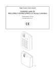
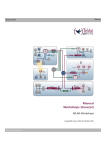
CPR32-SE_EN.doc
www.roger.pl
C P R 3 2-SE
CONTROL PANEL
FOR
ROGER ACCESS CONTROL SYSTEM
Introduction
The CPR access control panel is a part of Roger Access Control System (RACS). Generally the device is dedicated for systems
which incorporate PR301 and PR201 access controllers but it can also be used with newly developed PRxx2 series (PR302,
PR302LCD and PR402). The main function of CPR is to collect all events which occurred on access controllers and save them in
its internal memory buffer. When CPR is used with PRxx2 controllers (which are equipped with events memory) it might be used
as remote, “high security” events buffer, when CPR operates with PRxx1 controllers it delivers events buffering function plus
controls time related functions on controllers (when operating in standalone mode PRxx1 controllers doesn’t offer time schedules
nor events buffering).
Note: For access systems managed by RACS 3 version software the use of CPR control panels is obligatory, the newly developed
RACS 4 access system managing software may operate with systems (or networks) which are equipped with CPR control panels
or which are not. When RACS 4 is used to manage access networks which incorporate PR301/201 access controllers but without
CPR the RACS 4 delivers real time clock to PR301/201 controllers and register events which occurred in system, without
computer in on-line mode both mentioned functionality disappears.
Specification
-
1.5A buffered power supply,
battery backed up time/date clock,
flash memory for configuration and events history,
256.000 event memory buffer,
RS485 interface,
Alarm output,
TAMPER input,
battery protection against deep discharge,
battery charging control circuit,
metal case with compartment for 7Ah battery.
04-06-23
Connection Terminals Description
Battery Connection – RED and BLACK wires
A 12V 7Ah rechargeable battery is used as a backup source of power in the event of an AC power failure. The battery also
provides additional current when the equipment connected to panel demands exceed the power output of the transformer, such as
when door strike energizing or activating signaling device (e.g. alarm siren). Electronic circuit monitors reserve battery voltage
level, when it falls below ~12V the Low Battery alarm is signalized, when it falls below ~11.5V the Battery Failure alarm is
signalized, when battery level drop below ∼10V electronic circuit automatically disconnect battery, entire system goes down.
Automatic disconnection of battery protects it from deep discharge and access system from operation below minimum acceptable
supply voltage. CPR charges battery with stable current, this method guarantee relatively quick and safe battery charging process.
The supply output voltage is factory set to 13.8V but it can vary from 11.0 to 13.8V, this depends on actual battery charging phase.
When output level is above 13.5V it means that battery is nearly charged, when levels drop below 12.0V it indicates that battery is
on beginning phase of charging.
Note: Do not connect the battery until all other wiring is complete. Connect the battery before connecting AC.
Connect the RED battery lead to the positive battery terminal; connect the black lead to negative.
AC terminals - AC
The panel requires 18-22V 30VA transformer. Connect the primary side of transformer to unswitched AC source and secondary
side to AC terminals.
Note: Do not connect transformer until all other wiring is complete.
Auxiliary Power Terminals – [+AUX-]
These terminals provide up to 1A of additional current at 12V DC for devices requiring power. Connect the positive side of any
device requiring power to AUX+ terminal, the negative side to AUX- (GND-ground). The AUX output is protected, when too much
current is drawn from these terminals AUX output will be temporarily shut off until the problem is corrected.
Communication Lines – A and B
CPR is equipped with RS485 communication interface. This standard of transmission guarantee up to 1200 meters
communication distance with high immunity against interferences. Installer may use arbitrary communication bus topology (star,
three or any combination of both), no terminating resistors are required. In most cases communication runs satisfactory on almost
each types of cables (twisted/untwisted, shielded/unshielded) but it is not guaranteed in each case. Generally unshielded, twisted
type cables are preferred and guarantee best performance of communication.
Installation
TAMPER Input – IN2
Locate the panel in a dry area close to unswitched AC power source. CPR should be mounted in protected location, all electrical
connections must be made with power supply off.
This input is dedicated to supervise TAMPER contacts of CPR and other devices installed in access system. Normally this input
must be shorted to supply minus (GND –ground), this situation is achieved when all TAMPER contacts are closed. If at least one
TAMPER contact is open a TAMPER alarm is generated.
Note: You must complete all wiring before connecting the battery, or applying AC to the panel.
ALARM Output – REL1 (NO1, COM1, NC1)
Once wiring is complete, power up the control panel. First connect the RED battery lead to the positive terminal and the BLACK to
lead to negative. Then, connect the AC. The panel must be thoroughly tested to ensure that all features and functions are
operating.
!
!
!
!
!
We recommend to ground AUX minus terminal (connect to earth),
Do not connect AUX plus output with other supplies plus outputs,
The minus terminals of each power supply and CPR should be connected together, this will guarantee that each
GND will have the same potential referred to earth,
Do not change settings of potentiometers located on CPR board,
CPR panel can be connected to RACS communication bus (A and B lines) in any location
Memory Reset Procedure
The MEMORY RESET procedure clears all existing data in CPR memory (configuration settings and events register). The CPR
Memory Reset can be performed from PR Master software (“Initialize” command) or can be performed in hardware manner. The
second method requires following steps:
Press Memory Reset switch and keep it pressed,
While Memory Reset switch is pressed press for a moment uP Reset switch,
Release Memory Reset switch,
The entire contents of CPR memory will be erased, panel requires new programming.
Note: The device is delivered with empty (default) configuration settings and do not require the memory reset procedure.
An ALARM line is an open drain, N-MOS type, transistor output. This output can sink up to 1A current for unlimited time. In normal
(not triggered) condition output remain in high impedance state, when triggered it move to low resistance state which results that
supply minus is observed on output.
Cancel Input – IO1
This input can be used to cancel alarm signalization on REL1 output and on optional BUZZER connected to IO2 line. This input
became triggered when shorted with supply minus (GND - ground).
BUZZER Output – IO2
This output is dedicated to control an optional BUZZER which can be used to signalize alarm and other condition of CPR control
panel. The IO2 line is an open drain transistor output which normally stay in high resistance state, when triggered it switch to
supply minus. The maximum current which may be sink by this output is internally limited to 1A value.
Note: BUZZER connect to IO2 output must have internal generator circuit with nominal 12V DC supply voltage.
Additional Supply Terminals – TMS+ and TMSThese terminals provide up to 200mA of additional current at 12V DC for devices requiring power. Connect the positive side of any
device requiring power to TMS+ terminal, the negative side to TMS-- (GND-ground). The TMS output is protected, when too much
current is drawn from these terminals TMS output will be temporarily shut off until the problem is corrected.
Reserved Terminals – REL2, IN2, IN3, IN4, CLK, DATA
Those terminals are reserved for further use, actually they have not assigned any functionality.
CPR32-SE_EN.doc
www.roger.pl
04-06-23
Functional Description
The CPR control panel may operate in ON or OFF mode. When CPR is stay in ON mode it continuously downloads events which
had been occurred on all access controllers located in network and save them in its internal memory banks, additionally it controls
time related functions (e.g. time schedules) on PR301/PR201 controllers. When CPR stay in OFF mode it stops its normal
operation – this mode is dedicated for service purpose only. Generally the CPR control panel is dedicated for access control
systems which use PR301 and PR201 controllers. Those controllers are not equipped with internal events buffers nor real time
clocks – CPR delivers both this features to PR301/PR201 family. When CPR is used in systems which incorporate PRxx2 series
of controllers it operates as remote and high security events buffer only. The PRxx2 controllers are equipped with internal memory
buffers and real time clock – the lack of CPR doesn’t reduce PRxx2 functionality. The CPR can be used in mixed systems which
are equipped with PRxx1 and PRxx2 series controllers, it automatically adopts its operation to different types of controllers which
are installed in access network.
Ordering information
CPR32-SE
CPR control panel with metal case.
CPR32-SE-MOD
CPR control panel electronic module (without casings).
Technical Specification
Power supply
Firmware upgrade
The internal control program of CPR’s microcontroller can be upgrade with new firmware versions. The procedure of upgrade is
called flashing and can be performed by authorized person (installer) without replacement of any memory chips nor returning
device to manufacturer. The detailed description of firmware upgrading can be found in Firmware Upgrade manual which can be
downloaded from www.roger.pl
220..230V AC
Power consumption:
30W
Supply Output (nominal)
13.8 V dc
Battery Charging Current
∼300 mA
Battery Cut Off Level
∼ 10.0 V
Optical and Acoustic signalization
Operating temp. range
0...+55º C.
Every alarm situation is signalized through LED located on CPR board and on BUZZER and ALARM outputs. The signalization on
ALARM output and Buzzer starts immediately after any alarm situation is detected and ceased automatically after 250 seconds
from a moment when last alarm occurred. A signalization on ALARM and BUZZER outputs can be cancelled manually by
triggering Cancel Input (IO1) or remotely from supervising PC. A signalization on LED can not be cancelled, it last until last alarm
condition disappear. Some of the alarms can be forbidden through PR Master (see CPR settings window from Networks menu).
Cable distance between CPR and controller or
PC computer
Max. 1200 meters (4000 ft)
Operating humidity
10 to 95% (non condensing)
LED
Description
Tamper
The violation of TAMPER loop was detected, non authorized access to access equipment
occurred.
Operation Suspended
CPR set to OFF mode, events registering stopped.
Low Battery
Low level of reserve battery, installer should be called immediately.
AC Lost
Lack of AC supply, signalization occur when CPR detects a lack of AC voltage for 15 minutes
period signalization stops immediately after AC supply return.
Memory Full
Dimensions (mm):
280 x 290 x 80
Weight (grams):
~3.5 kG
Connection terminals assignment
AC
+ AUX NO1
When this LED blinks, this means that 75% of CPR memory is occupied, operator should transfer
the contents of CPR memory to the PC database otherwise the events memory overflow can
occur. When this LED is set continuously it indicates that buffer is fully occupied, some events
where lost.
COM1
TXD
Data transmitted from CPR.
COM2
RXD
Data incoming to CPR.
Note: When all LED blinks periodically it means that CPR’s settings are corrupted, operator must Reset CPR Memory and then
fully download it with new ones.
AC supply input, 30VA 18-22VAC transformer
Supply output 12V/1A
REL1 output, normally open contact
REL1 output, common contact
NC1
REL1 output, normally closed contact
NO2
REL2 output, normally open contact
REL2 output, common contact
NC2
REL2 output, normally closed contact
IO1
Transistor output, 1A/16V DC max.
IO2
Transistor output, 1A/16V DC max.
IN1
IN1 input line
COM
IN2
IN3
COM
IN4
A
REL1 relay output, 1.5A/24V DC or AC
REL2 relay output, 1.5A/24V DC or AC
IN1 and IN2 common terminal, internally connected with supply minus
IN2 input line
IN3 input line
IN3 and IN4 common terminal, internally connected with supply minus
IN4 input line
RS485 communication bus, terminal “A”
B
RS485 communication bus, terminal “B”
SHLD
RS485 communication bus, cable shield
CLK
Clock & Data interface, Clock line
DATA
Clock & Data interface, Data line
+ TS -
Terminal supply, max. 200mA
BATTERY CHARGING
TAMPER
OFF MODE
Output
Battery Charge A/D Conv.
Voltage
Calibration
Regulation Regulation
POT1
POT3
POT2
LOW BATTERY
AC LOST
BUFFER FULL
Firmware
Download
Mode
S1
Memory
Reset
S2
uP
Reset
+ACC-
AC
NC1
NO2
COM2
NC2
IO1
IO2
IN1
COM
IN2
IN3
COM
Alarm cancelling input
Alarm Signalization
IN4
A
B
CLOCK
DATA
RS485 SHLD
+ TS Unshielded, twisted cables are preferred
Cables with shield should be used
only when strong electrical
interferences exists
Rs485 Communication bus
Buzzer control output (max 1A)
TRANSFORMER
30VA, 18-22VAC
COM1
REL1 output
Sealed gel battery
7Ah/12 V
NO1
18… 22 VAC
Max 1A
230VAC
+ AUX -
TAMPER
Alarm Cancel Button
(NO type)
TAMPER loop
12V DC Buzzer
CPR32-SE installation diagram
Cdr121EN