1
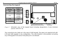
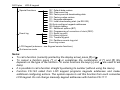
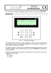
CA10 plus
LCD-S keypad
9
In the case of standard 8x0.5 cable to ensure proper keypad function the following number of
wires versus the panel-keypad distance should be used.
Distance
Connection
Number of wires
up to 50 m
KPD and COM
CLK and DTA signals
2x1
2x1
KPD and COM
CLK and DTA signals
KPD and COM
CLK and DTA signals
2x2
2x1
2x4
2x1
up to 100 m
up to 200 m
Note:
the keypad power supply voltage (measured between "KPD" and "COM" on the
keypad side) must not drop below 11V when the back-lighting is on.
After the control panel power up, the keypad can display message "Change panel's EPROM
or set the correct keypad address". This is usually because the keypad address is different
than the one programmed in the panel. In this case start the panel according to the
instructions in -"CA10 plus Programming Manual", section "Starting the Control Panel".
NOTE: We recommend keypads: CA-10 LED M v1.2 and CA-10 LED S v1.2 or newer to be
used, because older keypads LED M and LED S may work incorrect with keypad LCD v3.08
(and next version).