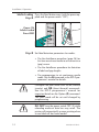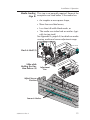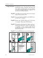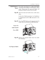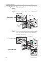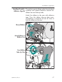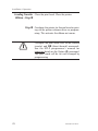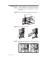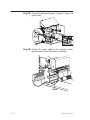
1
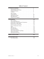
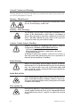
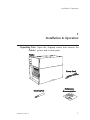
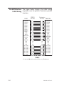
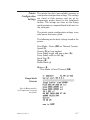
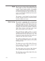
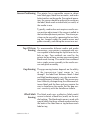
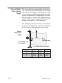
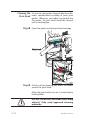
Thermal Printer
User’s Manual
Model 2746
User’s Manual No. 980295-001
©1999 Zebra Technologies Corporation
Rev. A
COPYRIGHT NOTICE
This document contains information proprietary to Zebra Technologies Corporation. This document and the information contained within is copyrighted by Zebra Technologies Corporation and
may not be duplicated in full or in part by any person without written approval from Zebra. While
every effort has been made to keep the information contained within current and accurate as of the
date of publication, no guarantee is given or implied that the document is error-free or that it is accurate with regard to any specification. Zebra reserves the right to make changes, for the purpose of
product improvement, at any time.
TRADEMARKS
2746 is a service mark and Zebra is a trademark of Zebra Technologies Corporation. Windows and
MS-DOS are registered trademarks of Microsoft Corp. All other marks are trademarks or registered
trademarks of their respective holders.
2746 Thermal Printer
European Council
Directive
Compliance to Standards
89/336/EEC EMC Directive EN55022-A, CISPR 22
RF Emissions control
92/31/EE
EMC Directive
EN50082-1 IEC801
Immunity to Electromagnetic Distrubances
73/23/EEC
Low Voltage
Directive
EN60950 IEC950
Product Safety
EMC Directive
EN61000-3-2
Harmonic Emmissions
EMC Directive
EN61000-3-3
Voltage Variation
FCC - DECLARATION OF CONFORMITY:
Model: 2746 conforms to the following specification:
FCC Part 15, Subpart B, Section 15.107(a) and Section
15.109(a) Class B digital device
Supplemental Information:
This device complies with Part 15 of the FCC Rules. Operation is subject to the following Two Conditions: (1) This device may not cause harmful interference , and (2) this device must accept any
interference received, including interference that may cause undesired operation.
INDUSTRY CANADA NOTICE:
This device complies with Industry Canada ICS-003 class B requirements.
Cet equipement est conforme a l’ICS-003 classe B de la norm Industrielle Canadian
ii
980295-001 Rev.A
Table of Contents
Installation & Operation. . . . .
Unpacking Your Printer . . . .
Getting To Know Your Printer .
Controls & Indicators . . . . .
Installation . . . . . . . . . . .
Media Loading. . . . . . . . .
Using AutoSense. . . . . . . .
Label Dispense Mode . . . . .
Media Rewinding . . . . . . .
Loading Transfer Ribbon . . .
.
.
.
.
.
.
.
.
.
.
.
.
.
.
.
.
.
.
.
.
.
.
.
.
.
.
.
.
.
.
.
.
.
.
.
.
.
.
.
.
.
.
.
.
.
.
.
.
.
.
.
.
.
.
.
.
.
.
.
.
. . .
. . . .
. . . .
. . . .
. . . .
. . . .
. . . .
. . . .
. . . .
. . . .
.
.
.
.
.
.
.
.
.
.
.
.
.
.
.
.
.
.
.
.
1
1
2
4
5
7
16
17
22
26
Troubleshooting . . . . . . . . . . . . . . . .
Where to Start . . . . . . . . . . . . . . . . .
Other Support Resources . . . . . . . . . . .
Serial Interface Communication Configuration.
Serial Interface Cable Wiring. . . . . . . . . .
Parallel Interface Cable Wiring . . . . . . . . .
Printer Configuration Settings . . . . . . . . .
Media . . . . . . . . . . . . . . . . . . . . .
Media Sensing . . . . . . . . . . . . . . . . .
Sensor Positioning . . . . . . . . . . . . . . .
Top Of Form Sensing . . . . . . . . . . . . .
Gap and Index Hole Sensing Range . . . . . .
Cleaning Your Printer . . . . . . . . . . . . .
Cleaning the Print Head . . . . . . . . . . . .
.
.
.
.
.
.
.
.
.
.
.
.
.
.
.
.
.
.
.
.
.
.
.
.
.
.
.
.
. . .
. . . .
. . . .
. . . .
. . . .
. . . .
. . . .
. . . .
. . . .
. . . .
. . . .
. . . .
. . . .
. . . .
.
.
.
.
.
.
.
.
.
.
.
.
.
.
.
.
.
.
.
.
.
.
.
.
.
.
.
.
A-1
A-1
A-4
A-5
A-5
A-6
A-7
A-8
A-8
A-9
A-9
A-10
A-11
A-12
.
.
.
.
.
.
.
.
.
. . .
. . .
. . .
. . .
. . .
. . .
. . .
. . .
. . .
. . .
Supplies and Accessories . . . . . . . . . . . . . . . . . . B-1
Using the Media Cutter . . . . . . . . . . . . . . . . . . . C-1
Cutter Specifications . . . . . . . . . . . . . . . . . . . . . . C-2
980295-001 Rev.A
iii
General Cautions and Warnings
This page describes general safety and maintenance warnings and cautions for the printer and
are referenced throughout the manual.
Warning - Shock Hazard
The printer should never be operated in a location where it can
get wet. Personal injury could result.
Warning - Static Discharge
The discharge of electrostatic energy that accumulates on the
surface of the human body or other surfaces can damage or
destroy the print head or electronic components used in this
device. DO NOT TOUCH the print head or the electronic
components under the print head assembly.
Caution - Printer Setup & Handling
1)When installing or modifying the printer setup or
configuration, ALWAYS TURN POWER OFF Before:
A) Connecting any cables.
B) Performing any cleaning or maintenance operations.
C) Moving the printer.
2) Damage to the printer interface connector, accessories or
door may result from placing the printer on it’s front bezel or
backside during unpacking or handling.
Media Warning
Always use high quality approved labels and tags. If adhesive
backed labels are used that DO NOT lay flat on the backing
liner, the exposed edges may stick to the label guides and
rollers inside the printer, causing the label to peel off from the
liner and jam the printer.
Media Reload Hint
If you should run out of labels while printing, DO NOT turn the
power switch OFF (0) while reloading or data loss may occur.
The printer will automatically resume printing when a new label
or ribbon roll is loaded.
Print Quality Tip
Print density (darkness) is affected by the heat energy (density
setting) applied and by the print speed. Changing both Print
Speed and Density may be required to achieve the desired
results.
iv
980295-001 Rev.A
Installation & Operation
1
Installation & Operation
Unpacking Your Open the shipping carton and remove the
Printer printer and its accessories.
n
tio
ta
en e
r
um a
oc tw
D of
r S
se &
U
980295-001 Rev.A
1
Installation & Operation
Getting To Know
Your Printer
Controls
Front Access Door
(Pull to Open)
Front Door Insert
Media Access Door
(Lift Up & Out to Remove)
(Lift to Open)
Media Roll
Holder
Ribbon Core
(Shipped mounted on
Ribbon Tube)
Label Taken
Sensor
Platen
Roller
Liner "Peeler"
Gate
Rewind
Bracket
Print Head
Release Lever
Peel/Tear
Bar
Print Head
2
980295-001 Rev.A
Installation & Operation
Getting To Know
Your Printer
Label Mode
Switch
Serial Interface
Connector
Auxiliary Media Access
(Opening for Fan Fold &
External Media)
Parallel Interface
Connector
Power Switch and
Power Cord Module
Media Access Door
(Open)
Ribbon Take-Up
Tube
Ribbon Supply
Tube
Print Width
Adjustment
Knob
Platen
(Media Drive)
Roller Bracket
Media Sensor and
Guide
980295-001 Rev.A
Liner Rewind
Tube and Clip
3
Installation & Operation
Controls &
Indicators
0 = Off
ON
1 = On
Button
O
OFF
O
Power Switch
Function
Press Once - Halt batch printing.
PAUSE
Press Second Time - Resume batch
printing operation.
Press Once - Feed one label or “form”.
FEED
CANCEL
Press & Hold - Feed a single label, stop,
feed a single label, stop, and so on until
the FEED button is released.
Press Once - resets and terminates any
print operation in progress.
Indicator LEDs
Condition Report
POWER
ERROR
On Solid
OFF
Power On
Flashing
OFF
1) Pause
2) Print head open
Flashing
Flashing
Labels Out
OFF
On Solid
Hardware Error
Label Mode Switch
PEEL
Mode
Description
Peel
Print one label and pause. Remove label.
Prints next label. Repeats until print operation is completed. Use label liner
rewinder to peel the liner from the label.
Batch
Standard operation - Prints one or more
labels until the batch form (label) print
operation is complete.
BATC
H
4
980295-001 Rev.A
Installation & Operation
Installation The following steps will guide you through the
installation of the printer.
Step 1
Attach Power
2746
Part No
.
Serial : 120XXX-XX
No. : XX
X
XXXX
XX
Input Po
wer: 11
5VAC
6.3A
50/60Hz
PEEL
Check
Voltage
BATCH
PEEL
BATCH
Batch
Mode
O
O
0 = Off
See Warnings - Page iv
980295-001 Rev.A
5
Installation & Operation
Step 2
Attach Interface
Cable
BATC
H
Parallel
Interface
BATC
H
Serial
Interface
Step 3
Apply Power
O
O
I = On
6
980295-001 Rev.A
Installation & Operation
Media Loading Open the media access door.
Step 1
Step 2 Open the door.
Step 3 Open the print head.
PER MOT
EP
OR
ST
980295-001 Rev.A
7
Installation & Operation
Media Loading Open the media guide.
Step 4
m)
1004"
mm
)
Slide Media Guide to
Outside Stop (1)
1
P
EP
ER MO
TOR
ST
m)
1004"
mm
)
Rotate Media Guide
to Open (2)
P
EP
ER MO
TOR
ST
2
m)
1004"
mm
)
Media Guide Opened
P
EP
ER MO
TOR
ST
8
980295-001 Rev.A
Installation & Operation
Media Loading Load the media roll.
Step 5
980295-001 Rev.A
9
Installation & Operation
Media Loading Thread the media through the media sensor
Step 6 and guide assembly and under the print head.
Outside Wound
(50 2"
mm
)
(10 4"
0m
m)
Inside Wound
(50 2"
mm
)
(10 4"
0m
m)
Fan Fold
(50m2"
m)
(1004"
mm
)
Media Path
(Side View)
Open
10
Open
980295-001 Rev.A
Installation & Operation
Media Loading Slide the media to the inside of the printer.
Step 7 Place the media guide against the media.
Slide Media Inside
Rotate Media
Guide Down
Media Guide in
Locked Position
Adjust Media Guide
to Media Width
Media Guide Set
980295-001 Rev.A
11
Installation & Operation
Media Loading Close the print head.
Step 8
(50 2"
mm
)
(10 4"
0m
m)
Step 9 Remove excess media.
12
980295-001 Rev.A
Installation & Operation
Media Loading Adjust the label pressure control knob to match
Step : the width of the media in use.
Set Media Width
Label Width
Pressure Control
Knob Settings
2"(50mm) or Less
2" (50mm)
Greater Than 2" (50mm)
4" (100mm)
Step ; Close the door and cover.
980295-001 Rev.A
13
Installation & Operation
Media Loading Press the Feed button once (with the power apStep < plied and the power switch “ON”).
Power ON
Labels Loaded
Press FEED
POWE
PA U S
R
PA U S E
E
FEED
CANCEL
ERRO
RIBB
R
ON/P
APER
OUT
Step = Set label detection parameters for media:
• Use the AutoSense procedure (page 16) for
first time use of new media to set transmissive
(gap) sensor.
• Use the AutoSense procedure for detection
of label and gap lengths.
• Use programming to set continuous media
mode. See the Q command in the EPL2 programmer's manual for details.
Configure the print mode with the O (thermal
transfer) and OD (direct thermal) commands.
See the EPL2 programmer's manual for
important details on the Option (O) command.
The print mode will be set until changed by
programming.
DO NOT turn the power switch OFF (0) while
reloading media or data loss may result. The
printer will automatically resume printing when
a new label roll has been loaded.
14
980295-001 Rev.A
Installation & Operation
Media Loading This step is not normally required. Some of the
Step > exceptions are listed below. If the media has:
• An irregular or non-square shape,
• More than one label across,
• Less than full width black marks, or
• The media uses index hole or notches (typically for tag stock).
See Appendix A, page A-8, for details on media
sensing, media and sensor adjustment range.
Pinch & Hold (1)
Slide while
Holding the Fins,
then Release (2)
Adjustment
Fins
Adjust Sensor
Position
Sensor & Marker
980295-001 Rev.A
15
Installation & Operation
Using AutoSense A u t o S e n s e s e t s t h e s e n s it iv it y o f t h e
transmissive sensor, measures and stores the
form (label) and gap lengths. For more details
on media sensing see Appendix A, page A-8. To
activate the AutoSense feature:
Step 1 Load labels into the printer. Do not use the peel
mode. Printer power is ON.
Step 2 Press and hold the PAUSE and CANCEL buttons for one (1) second.
Step 3 Release the CANCEL button only. Wait three
(3) seconds. Release the PAUSE button.
Step 4 The printer will advance 3-4 labels while per-
forming the adjustment. When the adjustment
is complete, a status summary label will be
printed and the printer will be placed in Diagnostic Dump mode.
Step 5 Press the FEED button to exit the Dump mode.
Power ON
Media Loaded
Batch Mode
PAUSE & CANCEL
1 sec.
POWE
PA U S
R
PA U S E
PAUSE
3 sec.
POWE
PA U S
E
R
PA U S E
E
FEED
FEED
CANCEL
CANCEL
ERRO
RIBB
ERRO
R
ON/P
APER
RIBB
OUT
Sample: DUMP Mode
Printout
R
ON/P
APER
OUT
FEED
4 MO3257 3.18.01
Serial port : 96,N,8,1
Image buffer size:245K
Fmem:000,0K,019.9K avl
Gmem:000K,0241K avl
Emem:000K,0241K avl
I8,0,001 rY
S8 D12 R032,000 ZT UN
q0784 Q1227,034
Option:D
11 12 13
now in DUMP
16
POWE
PA U S
R
PA U S E
E
FEED
CANCEL
ERRO
RIBB
R
ON/P
APER
OUT
980295-001 Rev.A
Installation & Operation
Label Dispense The printer can dispense a single peeled label
Mode and rewind the backing in the Dispense (Peel)
mode. Removing the presented label will
prompt the printer to print the next label.
Step 1 Open the front and media access (side cover)
doors.
Load and set labels parameters (via AutoSense
or programmed with the Q command) in the
printer.
Step 2 Press the FEED button until approximately 16
inches (40 cm) of media has exited the printer.
Power ON
Labels Loaded
Press FEED
Step 3 Remove the exposed labels from the media
liner (backing).
Peel Exposed Labels
980295-001 Rev.A
17
Installation & Operation
Label Dispense Open liner peeler gate.
Mode - Step 4
Step 5 Thread the backing between the platen roller
bracket and the liner peeler gate.
18
980295-001 Rev.A
Installation & Operation
Label Dispense Attach the backing to the rewind tube with the
Mode - Step 6 clip.
Attach Liner to
Rewind Tube
Step 7 Turn the rewind tube counter-clockwise to
remove liner slack.
Close liner peeler gate. Close the print head.
Remove Liner Slack
Close Liner
Peeler Gate
Close the Print Head
980295-001 Rev.A
19
Installation & Operation
Label Dispense Change the printer mode switch to “Peel”.
Mode - Step 8
Press the CANCEL button to initiate Label Dispense Mode to peel labels.
CANCEL
Switch to Peel Mode
PEEL
Press CANCEL
POWE
PA U S
R
PA U S E
E
FEED
BATCH
CANCEL
ERRO
Remove Slack (FEED)
RIBB
R
ON/P
APER
OUT
Step 9 Set the label taken sensor to the down (active)
position.
Label Taken Sensor
in Down Position
Close Printer
Press FEED
Close the printer's door and cover.
The front door must be closed for the label
taken sensor and the “peel” mode to work
properly.
Press the FEED button until the slack is removed from the media backing and the first label is presented (peeled).
20
980295-001 Rev.A
Installation & Operation
Label Dispense Remove the label. The printer is ready to print in
Mode - Step : the peel mode.
Label Presented,
Remove Label
(Media Path Shown)
PER MOT
EP
OR
ST
Present Label (FEED)
980295-001 Rev.A
21
Installation & Operation
Media Rewinding The rewinder allows the print and rewind of
partial label rolls.
Rewinder Capacity
The quantity of media re-rolled will vary due to
e n v i ro n m e n t a l c o n d it io n s a n d m e d ia
properties.
Step 1 Open the front and side media access doors.
Load and set media parameters (via AutoSense
or programming with the Q command) in the
printer.
Step 2 Remove door insert.
Lift (1)
Push Out (2)
Step 3 Open the label peeler gate and print head.
22
980295-001 Rev.A
Installation & Operation
Step 4 Get the rewind bracket and thumb screw.
Step 5 Place the rewind bracket into the peel/tear bar
assembly.
Step 6 Attach the rewind bracket to the printer with the
thumb screw.
980295-001 Rev.A
23
Installation & Operation
Step 7 Pull media out the front of the printer.
Remove exposed labels from liner, if any.
16 inches
(40cm)
Step 8 Attach the liner to the rewind tube with the clip.
Turn the rewind tube counter-clockwise to remove liner slack.
Close the print head.
Attach Media to
Rewind Tube
Close Print Head
24
980295-001 Rev.A
Installation & Operation
Step 9 Change the printer mode switch to “Batch”.
Press the CANCEL button to initiate batch label
processing for media rewinding.
CANCEL
PEEL
POWE
PA U S
R
PA U S E
E
FEED
BATCH
CANCEL
ERRO
RIBB
R
ON/P
APER
OUT
Step : Press the FEED button to remove slack and
wind one revolution of media around the rewind tube.
Close the printer doors.
980295-001 Rev.A
25
Installation & Operation
Loading Transfer Refer to the following instructions for installaRibbon tion of the ribbon.
Step 1 Insert an empty ribbon core on the ribbon
take-up tube.
Insert Ribbon Core
Ribbon
Core
Step 2 Insert a transfer ribbon roll on the ribbon supply
tube. The transfer ribbon unwinds clockwise.
Open the print head.
Insert Ribbon Roll
Open Print Head
26
980295-001 Rev.A
Installation & Operation
Loading Transfer Thread the transfer ribbon under the print head
Ribbon- Step 3 assembly and counter-clockwise around the
ribbon core and take-up tube.
Attach the ribbon to the core with adhesive
tape. Turn the ribbon take-up tube counter-clockwise a minimum of two (2) times to
lock the ribbon on the core.
Thread Ribbon
Attach Ribbon to
Ribbon Core
Tape
Turn Ribbon
Take-Up Tube
980295-001 Rev.A
27
Installation & Operation
Loading Transfer Close the print head. Close the printer.
Ribbon - Step 4
Step 5 Configure the printer for thermal transfer print-
ing via the printer software driver or programming. This activates the ribbon out sensor.
Configure the print mode with the O (thermal
transfer) and OD (direct thermal) commands.
See the EPL2 programmer's manual for
important details on the Option (O) command.
The print mode will be set until changed by
programming.
28
980295-001 Rev.A
Appendix A
Troubleshooting
This section addresses the most common issues
you may face with operation, maintenance and
configuration of the printer.
Where to Start Your first troubleshooting reference source is
the Common Problems Troubleshooting table
on the following page.
980295-001 Rev.A
A-1
Common Printing Problems
Troubleshooting Guide
Problem
Solution or Reason
STATUS indicator does
1. Check power connections from the printer to
not light GREEN when
the outlet.
power switch is turned
2. Check that media and ribbon are loaded.
to the ON (1) position.
1. Verify that the labels are the correct type.
With the STATUS
2. Check the roll and verify that the print surface
indicator light GREEN,
faces up for printing.
the printer appears to
3. Check that the transfer ribbon is correctly
be working, but
routed and has the ink side out for thermal
nothing is printed.
transfer printing, only.
Printing is faded or
poor quality.
1. Clean the print head with cleaning pen.
2. Adjust print speed/darkness in software or
with programming.
3. Check the roll and verify that the media print
surface is facing up.
4. Verify that the correct combination thermal
transfer ribbon and media are in use.
Printing stops and the
STATUS indicator
lights RED.
1. Possible problem sensing labels with transmissive
(gap) sensor. Perform AutoSense adjustment.
Align the transmissive (gap) sensor position, see
page 15.
2. Possible problem with label media.
a) Gap between the bottom of a label and the
top of the next label should be at least 1/16"
(1.6mm).
b) For tags, see Gap and Index Hole Sensing
Range, page A-10.
c) Use only Eltron approved labels and tags.
3. Possible label jam.
4. Check that the media is correctly routed.
5. Possible software/programming problem.
a) Check the printer memory configuration.
b) Refer to the EPL2 Programming manual
for the correct data syntax.
6. Transmissive sensor is dirty. Clean media path.
A-2
980295-001 Rev.A
Problem
Solution or Reason
1. Check for Out-of-Media condition or missing
labels in the middle of a roll.
2. Check for Out-of-Ribbon condition or damage or previous use of ribbon in middle of the
roll.
3. Check that the ribbon and label media are
correctly routed.
4. When direct thermal printing, verify that the
programmed mode (or printer driver) is set for
direct thermal printing. See the programmer’s
Status Indicator is RED
manual for details.
5. Transmissive (gap) sensor is dirty. Clean the
media path.
6. Verify that the print head carriage is closed
and latched.
7. Verify that the media sensor is correctly positioned to detect an inter label gap, index
holes (notches), or black mark (stripes). See
page 15 for sensor location and setting.
Printer cuts (melts)
through the transfer
ribbon. The ribbon is
advancing normally,
i.e. at the same rate as
the media.
1. Verify the density (heat) setting. If this is unknown reduce setting several levels the until
the transferred ink is clear and the ribbon is
not damaged.
2. Verify that the correct media is in use.
3. Verify that the ink (transfer material) side is
out on the transfer ribbon roll.
Label Dispense Mode:
Printing does not stop
between labels.
1. The Peel/Batch switch in the rear of the
printer is not set to peel.
2. The door is open or the label taken sensor is
not in the down (active) position. See page
20 for sensor location and setting.
Label Dispense Mode:
Prints one label and
stops.
1. Programming - Verify the quantity has been
correctly set.
Cutter Option:
Cutting labels instead
of cutting between
labels.
1. Programming - Verify form length setting.
2. Check that peel switch is in the "batch" position (towards outside of printer).
980295-001 Rev.A
A-3
Other Support Your first troubleshooting reference source is
Resources the table on the previous page. Next, contact
the dealer where you purchased your printer.
Zebra Technologies also provides a variety of
information and user support services:
• Internet:
Web Address: http://www.eltron.com
ftp: //ftp.eltron.com
e-mail:
Label Printers: [email protected]
Card Printers: [email protected]
Europe: [email protected]
Singapore: [email protected]
Latin America: [email protected]
• Customer Service: +1 (805) 579 1800
For the name of a dealer in your area.
• Technical Support FAX:
USA: +1 (805) 579 1808
Asia: +65 84 20 366
Northern Europe: +44 (0) 1189 895 762
Southern Europe: +33 (0) 240 097 070
Latin America: +1 (847) 584 2725
For your assistance and support with Eltron
printers and software.
A-4
980295-001 Rev.A
Serial Interface The printer’s serial port is configured with the
Communication Y command for the printer. See the EPL2 proConfiguration grammer's manual for details.
The printer’s serial port default configuration is:
9600 baud
8 bit data
1 stop bit
No parity
Serial Interface The figure below displays the cable wiring reCable Wiring quired to use the printer’s serial interface
Host
N/C
RxD
TxD
DTR
GND
DSR
RTS
CTS
RI
DB-9
Pin #
1
2
3
4
5
6
7
8
9
DB-9
Pin #
1
2
3
4
5
6
7
8
9
Printer
+5 Volts*
TxD
RxD
N/C
GND
RDY
N/C
RDY
N/C
Female DB-9 to Male DB-9
Host
N/C
RxD
TxD
DTR
GND
DSR
RTS
CTS
RI
DB-25
Pin #
8
3
2
20
7
6
4
5
22
DB-9
Pin #
1
2
3
4
5
6
7
8
9
Printer
+5 Volts*
TxD
RxD
N/C
GND
RDY
N/C
RDY
N/C
Female DB-25 to Male DB-9
*+5 volts at 150 mA for external device (e.g. KDU or scanner)
980295-001 Rev.A
A-5
Parallel Interface The figure below displays the cable wiring
Cable Wiring required to use the printer's Centronics parallel
interface.
HOST
DB-25
Pin No.
STROBE
DATA 0
DATA 1
DATA 2
DATA 3
DATA 4
DATA 5
DATA 6
DATA 7
ACK/
BUSY
PAPER ERR.
READY
INIT
ERROR/
N/A
N/A
N/A
SIG. GND
SIG. GND
SIG. GND
SIG. GND
SIG. GND
SIG. GND
SIG. GND
1
2
3
4
5
6
7
8
9
10
11
12
13
14
15
16
17
18
19
20
21
22
23
24
25
Centronics
Pin No. PRINTER
1
2
3
4
5
6
7
8
9
10
11
12
13
14
15
16
17
18
19
20
21
22
23
24
25
STROBE
DATA 0
DATA 1
DATA 2
DATA 3
DATA 4
DATA 5
DATA 6
DATA 7
ACK/
BUSY
PAPER ERR.
READY
INIT
ERROR/
N/A
N/A
+5V
SIG. GND
SIG. GND
SIG. GND
SIG. GND
SIG. GND
SIG. GND
Female DB-25 to Male Centronics
(Cable)
+5 volts at 300 mA for external device (e.g. PrintServer)
A-6
980295-001 Rev.A
Printer The printer has flash (non-volatile) memory to
Configuration store printer configuration settings. The settings
Settings are stored in flash memory and are set by
programing, printer drivers or the AutoSense
routine. The settings are show on the Dump
mode printout or a reported back to the host via
the serial port.
The printer retains configuration settings, even
after power has been cycled.
The following are the basic settings stored in the
printer.:
Print Mode - Direct (OD) or Thermal Transfer
Speed (S)
Density (D) or heat applied
Form (label) length and gap in dots (Q)
Form (label) width in dots (q)
Serial Port (Y)
Margin (R)
Buffer Mode (r)
Options: D
Print Mode is Direct Thermal (OD)
Dump Mode
Printout
(See the U command in
the Programmer’s manual
for details)
980295-001 Rev.A
A-7
Media The two types of print media supported by the
2746 printer are direct thermal and thermal
transfer. Direct thermal media is chemically
treated to produce print without a ribbon. Thermal transfer printing uses heat to transfer wax,
resin or a combination of both from the transfer
ribbon to the media.
The printer is set by default to direct thermal
printing. Setting the printer to thermal transfer
activate a ribbon out sensor.
Media Sensing The printer is equipped with a transmissive
(gap) sensor, reflective (black mark) sensor, and
a reflective ribbon out sensor. These sensors are
adjustable and are located in the media sensor
assembly. The printer also includes a reflective
(label taken) sensor in the door and a head
open sensor located in the inside wall.
The transmissive (gap) sensor is set by
AutoSense function and adjusts the sensitivity
and detection levels for the media in use. The
transmissive sensor also detects the media out
condition and index hole or notches.
The reflective (black mark) sensor senses light
(media) and dark (black marks) on the media
backing (or liner).
The ribbon out sensor reflects light off the print
head assembly. When ribbon is present (and
unused), the light is stopped.
The label taken sensor receives light reflected
from a peeled label waiting to be removed.
The head open sensor reflects light off the side
of an open print head.
A-8
980295-001 Rev.A
Sensor Positioning The printer has a moveable sensor to detect
inter label gaps, black lines or marks, and index
holes/notches on the media. For optimal operation, the sensor should be adjusted to center on
the label, black mark or index hole (or notch) of
the media in use.
Typically, media does not require a media sensor position adjustment if the sensor is pulled to
the outside adjustment position. The sensor position can be moved by squeezing the two locking fins, located under the media sensor and
guide assembly, and sliding the sensor in or out.
Top Of Form To accommodate different media and media
Sensing dimensions, your printer is equipped with sen-
sors capable of detecting the top of form for labels or tags. Two methods are used by the
printer for top of form sensing: gap sensing and
black mark sensing. The sensors are combined
into a single sensor assembly in the media sensor and guide assembly.
Gap Sensing The gap sensing feature depends on the ability
of the transmissive (gap) sensor to “see
through” the label liner between labels. Label
and label backing opacity vary due to manufacturing differences in label stock. The sensor may
have difficulty distinguishing the difference between labels and the liner and may require the
user to AutoSense the media. Set the gap sensor’s sensitivity with the AutoSense feature.
Black Mark The black mark uses a reflective (black mark)
Sensing sensor to detect a black line (mark) on the media backing. The black mark sensor is used with
special labels that have a black mark printed on
the back of the label liner or tag between each
label or tag.
980295-001 Rev.A
A-9
Gap and Index The sensor position is indicated by the green arHole Sensing row at the front of the label guide that is visible
Range with the print head open and media out. The
sensor can be moved by squeezing the two locking tabs, located under the label guide, and sliding the sensor in or out. For proper sensing,
ensure that the sensor is aligned with the center
portion of the label or index hole/notch.
The following dimensions show the required
position of the index hole or notch on tag stock
for the printer to demonstrate sensor range.
C
min.
Sensor
Adjustment
Range
max.
B
A
Tag Tear-away
Inside Edge
of Tag Stock
.314 Nominal Sensor Location
A-10
Dimension
Min.
Max.
Nominal
A
.236"
None
.512"
B
.079"
.512"
.118"
C
.098"
1.520"
N/A
980295-001 Rev.A
Cleaning Your The printer’s media path allows for cleaning
Printer and clearing of media jams. The user can clean
the print head, platen roller and areas adjacent
to the media path surfaces.
Warning -Shock Hazard - See page iv.
Always turn the printer off before cleaning.
The media path surfaces (except the print head)
can be cleaned with a lint free, clean, damp
cloth very lightly moistened with medical grade
alcohol. Alcohol may be used to help remove
any adhesive or label material buildup.
Warning - Static Discharge - See page iv.
Never touch the print head. Always clean the
print head with a cleaning pen (to protect the
print head from static discharge and fibers).
If a label has become jammed in the printer,
remove the label and any adhesive residue,
immediately. Adhesive may spread through out
the printer’s media path if not completely
removed. Many adhesives are permanent and
have short “set” times.
980295-001 Rev.A
A-11
Cleaning the As you use your printer, the print head may bePrint Head come contaminated resulting in poor print
quality. Whenever new labels are loaded into
the printer, the print head should be cleaned
with a cleaning pen.
Step 1 Open the printer and the print head carriage.
Step 2 Gently rub the cleaning pen across the amber
area of the print head.
Allow the print head to dry for 1 minute before
loading labels.
Do Not Clean the Print Head with sharp
objects! Only used approved cleaning
materials.
A-12
980295-001 Rev.A
Appendix B
Supplies and Accessories
Accessories available for the 2746 printer are
listed below. Always refer to the ELTRON part
number when placing an order. For the name
of an Eltron brand dealer in your area, call:
1(800) 344-4003 (1 (805) 579-1800) or the
nearest Zebra Technologies office (located on
the back of this manual).
Description
Part Number
Parallel Interface Cable, 6’
Parallel Interface Cable, 10’
Serial Interface Cable, 6’ (DB-9 to DB-9)
Serial Interface Cable, 10’ (DB-9 to DB-9)
Serial Interface Cable, 6’ (DB-25 to DB-9)
300016-006
300016-010
300017-006
300017-010
300018-006
KDU (Keyboard Display Unit)
120180-001
Windows Printer Driver
Create-A-Label 3 for Windows
105501-003
105524-001
User’s Manual (this Manual)
Programmer’s Manual
980295-001
980009-001
980295-001 Rev.A
B-1
B-2
980295-001 Rev.A
Appendix C
Using the Media Cutter
Printers with the cutter option have a detachable cutter with a motorized blade. The cutter is
a self cleaning tag and label liner cutter.
Printers with cutters can dispense a single form
(label) that is automatically cut from the media
roll.
Guidelines Use the cutter to cut through continuous paper
from rolls and the liner between labels. Never
cut the portion of media that has adhesive or
adhesive backing.
You can switch cutting on and off by using the
OC command. You can set form length and
gap distances by using the Q command. Refer
to the EPL2 programmer’s manual for complete
programming information.
Keep the cutter dry. Never use any solutions or
solvents to clean the blade. If there is a jam, follow the steps for Clearing the Cutter.
980295-001 Rev.A
C-1
Cutter The cutter option is a field install able option,
Specifications only. The printer covers must be opened to gain
access to the main PCB to install the cutter. This
installation should be performed by qualified
service personnel.
Warranty
90 Days
Mean Time To
Failure (MTBF)
500,000 cut cycles
Cutting Method
Rotating, double edged blade
Media
Media Type
Paper, Thermal Paper, Paper Tags, Paper Label Liners
Max. Density
120 grams/meter2
(approximately 0.053 inches (0.134 mm) thick)
Min. Width
1.0 inches (25.4 mm)
Max. Width
4.13 inches (105 mm)
Once installed the cutter is removable to allow
printing in non cutter configurations.
Clearing the The only tool required to clear a jam is a pair of
Cutter small tweezers. Never use your fingers or sharp
objects to clear jams.
If you cannot remove the jammed media, call
for service.
C-2
980295-001 Rev.A
Mounting the Use this procedure to attach and remove a preCutter viously installed cutter on the printer. The operator should reverse the procedure to remove
the cutter.
Step 1 Open the front and side media access doors.
Step 2 Remove the door insert.
Step 3
980295-001 Rev.A
Place the label taken sensor in the up (inactive)
position.
C-3
Step 4 Open the label peeler gate. Optional - Open the
print head.
Step 5 Attach the cutter cable to the printer’s cutter
plug located under the platen assembly.
Attach
C-4
980295-001 Rev.A
Step 6 Place the cutter onto the peel/tear bar.
Place Cutter
Route Cable
Through
Peeler Gate
Step 7 Lock the cutter in place with the thumbscrew.
Attach Cutter
to Printer
980295-001 Rev.A
C-5
Step 8 Close the door.
Step 9 Load media as required. Configure the printer
for the selected media with the AutoSense routine or programming. Continuous media and
black line or mark media required programming for proper configuration.
Step : Configure the printer for cutting with program-
ming. See the programmer’s manual for details
on setting and canceling cutter printer command settings.
C-6
980295-001 Rev.A