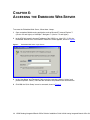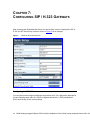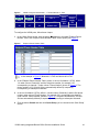
1
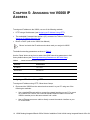
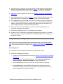
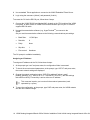
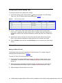
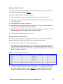
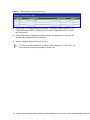
V6000 Analog Integrated Branch Office Solution Installation Guide System Release 4.8 http://www.3com.com Part Number 900-0387-01 Published November 2006 3Com Corporation, 350 Campus Drive, Marlborough, MA 01752-3064 Copyright © 2006, 3Com Corporation. All Rights Reserved. No part of this documentation may be reproduced in any form or by any means or used to make any derivative work (such as translation, transformation, or adaptation) without written permission from 3Com Corporation. 3Com Corporation reserves the right to revise this documentation and to make changes in content from time to time without obligation on the part of 3Com Corporation to provide notification of such revision or change. 3Com Corporation provides this documentation without warranty, term, or condition of any kind, either implied or expressed, including, but not limited to, the implied warranties, terms, or conditions of merchantability, satisfactory quality, and fitness for a particular purpose. 3Com may make improvements or changes in the product(s) and/or the program(s) described in this documentation at any time. If there is any software on removable media described in this documentation, it is furnished under a license agreement included with the product as a separate document, in the hardcopy documentation, or on the removable media in a directory file named LICENSE.TXT or !LICENSE.TXT. If you are unable to locate a copy, please contact 3Com and a copy will be provided to you. UNITED STATES GOVERNMENT LEGEND If you are a United States government agency, then this documentation and the software described herein are provided to you subject to the following: All technical data and computer software are commercial in nature and developed solely at private expense. Software is delivered as “Commercial Computer Software” as defined in DFARS 252.227-7014 (June 1995) or as a “commercial item” as defined in FAR 2.101(a) and as such is provided with only such rights as are provided in 3Com’s standard commercial license for the Software. Technical data is provided with limited rights only as provided in DFAR 252.227-7015 (Nov 1995) or FAR 52.227-14 (June 1987), whichever is applicable. You agree not to remove or deface any portion of any legend provided on any licensed program or documentation contained in, or delivered to you in conjunction with, this guide. Unless otherwise indicated, 3Com registered trademarks are registered in the United States and may or may not be registered in other countries. 3Com, the 3Com logo, and VCX are registered trademarks of 3Com Corporation. All other company and product names may be trademarks of the respective companies with which they are associated. 2 V6000 Analog Integrated Branch Office Solution Installation Guide V6000 Analog Integrated Branch Office Sol CONTENTS ABOUT THIS GUIDE 5 How to Use This Guide 5 Conventions 6 Related Documentation 6 Documentation Comments 6 Notices 7 WEEE EU Directive 7 Abbreviations and Terminology 7 CHAPTER 1: QUICK START 9 CHAPTER 2: UNPACKING THE V6000 10 CHAPTER 3: MOUNTING THE V6000 12 CHAPTER 4: CABLING THE V6000 14 CHAPTER 5: ASSIGNING THE V6000 IP ADDRESS 16 Assigning an IP Address Using HTTP 16 Assign an IP Address Using the CLI 17 Accessing the CLI 17 Assigning an IP Address 18 Restoring Networking Parameters to the Initial State 19 CHAPTER 6: ACCESSING THE EMBEDDED WEB SERVER 20 CHAPTER 7: CONFIGURING SIP / H.323 GATEWAYS 22 Configuring the V6000 Ports 22 Configuring the Internal Routing Table 24 Making Calls 24 Making an FXS to FXS Call 24 V6000 Analog Integrated Branch Office Solution Installation Guide 3 Making an FXS to FXO Call 25 Making a V6000 to MP-104 FXS Call 25 APPENDIX A: OBTAINING SUPPORT FOR YOUR 3COM PRODUCT 28 Customer Support 28 4 V6000 Analog Integrated Branch Office Solution Installation Guide V6000 Analog Integrated Branch Office Sol ABOUT THIS GUIDE This guide describes the installation of the 3Com V6000 analog integrated branch office solution gateways. Information contained in this document is believed to be accurate and reliable at the time of printing. However, because of on-going product improvements and revisions, 3Com cannot guarantee the accuracy of printed material after the Date Published nor can it accept responsibility for errors or omissions. Updates to this document and other documents can be viewed by registered Technical Support customers at http://www.3Com.com under Support / Product Documentation. When viewing this manual on CD, Web site or on any other electronic copy, all cross-references are hyperlinked. Click on the page or section titles (shown in blue) to reach the individual cross-referenced item directly. To return back to the point from where you accessed the cross-reference, press the ALT and ◄ keys. How to Use This Guide This book covers these topics: Chapter 1: Quick Start Chapter 2: Unpacking the V6000 Chapter 3: Mounting the V6000 Chapter 4: Cabling the V6000 Chapter 5: Assigning the V6000 IP Address Chapter 6: Accessing the Embedded Web Server Chapter 7: Configuring SIP / H.323 Gateways V6000 Analog Integrated Branch Office Solution Installation Guide 5 Conventions Table 1 lists conventions that are used throughout this guide. Table 1 Icon Notice Icons Notice Type Description Information note Information that describes important features or instructions. Caution Information that alerts you to potential loss of data or potential damage to an application, device, system, or network. Warning Information that alerts you to potential personal injury or death. Related Documentation The following documents are available on the 3Com Partner Access Web site for the 3Com V6000 SIP and H.323 analog VoIP gateways: 900-0388-01 V6000 Analog Integrated Branch Office Solution User Guide 900-0390-01 V6000 and V7111 Analog Integrated Branch Office Solution Release Notes Documentation Comments Your suggestions are important to us because we want to make our documentation more useful to you. Please send e-mail comments about this guide or any of the V6000 documentation to: [email protected] 6 V6000 Analog Integrated Branch Office Solution Installation Guide V6000 Analog Integrated Branch Office Sol Please include the following information with your comments: Document title Document part number (usually found on the front page) Page number Your name and organization (optional) Example: 3Com V6000 Guide Part Number Page 25 See the Appendix Obtaining Support for Your Product in the V6000 Digital Guide for details on how to register your product and get support from 3Com. Notices WEEE EU Directive Pursuant to the WEEE EU Directive, electronic and electrical waste must not be disposed of with unsorted waste. Please contact your local recycling authority for disposal of this product. Abbreviations and Terminology Each abbreviation, unless widely used, is spelled out in full when first used, and only Industry standard terms are used throughout this manual. The symbol 0x indicates hexadecimal notation. WARNING: The V6000 is supplied as a sealed unit and must only be serviced by qualified service personnel Ensure that you connect FXS ports to analog telephone devices only, and FXO ports to CO/PBX lines only. To protect against electrical shock and fire, use a 26 AWG min wire to connect FXO ports to Public Switching Telephone Network (PSTN). V6000 Analog Integrated Branch Office Solution Installation Guide 7 Where ‘network’ appears in this manual, it means LAN, WAN, etc. accessed via the gateway’s Ethernet interface. FXO (Foreign Exchange Office) is the interface replacing the analog telephone and connects to a Public Switched Telephone Network (PSTN) line from the Central Office (CO) or to a Private Branch Exchange (PBX). The FXO is designed to receive line voltage and ringing current, supplied from the CO or the PBX (just like an analog telephone). An FXO VoIP gateway interfaces between the CO/PBX line and the Internet. FXS (Foreign Exchange Station) is the interface replacing the Exchange (i.e., the CO or the PBX) and connects to analog telephones, dial-up modems, and fax machines. The FXS is designed to supply line voltage and ringing current to these telephone devices. An FXS VoIP gateway interfaces between the analog telephone devices and the Internet. The FXO port is considered to be TNV-3. FXS ports are considered to be TNV-2. Each abbreviation, unless widely used, is spelled out in full when first used, and only Industry standard terms are used throughout this manual. The symbol 0x indicates hexadecimal notation. Pursuant to the WEEE EU Directive, electronic and electrical waste must not be disposed of with unsorted waste. Please contact your local recycling authority for disposal of this product. 8 V6000 Analog Integrated Branch Office Solution Installation Guide V6000 Analog Integrated Branch Office Sol CHAPTER 1: QUICK START This Guide takes you through the briefest steps that are required for setting up your V6000 for the first time and making a basic call. For more details on how to use the gateway’s full capability, refer to the V6000 User Manual. Follow these required steps to set up the V6000. 1 Unpack the V6000. 2 Mount the V6000. 3 Cable the V6000. 4 Assign the V6000 IP address. 5 Configure the V6000 ports. 6 Configure the internal routing table. 7 Make a call. V6000 Analog Integrated Branch Office Solution Installation Guide 9 CHAPTER 2: UNPACKING THE V6000 To unpack the V6000, follow these 6 steps: 1 Open the carton and remove packing materials. 2 Remove the V6000 from the carton. 3 Check that there is no equipment damage. 4 Check, retain and process any documents. 5 Notify 3Com or your local supplier of any damage or discrepancies. 6 Retain any diskettes or CDs. Ensure that in addition to the V6000, the package contains: One or two AC power cables. Four anti-slide bumpers for desktop installation option (supplied in a small plastic bag). RS-232 DB9 adapting cable, two meters in length (direct connection to PC). CD (software and documentation). Lifeline cable (RJ-11 adaptor cable), supplied with FXS I/O modules only. This V6000 Guide. 10 V6000 Analog Integrated Branch Office Solution Installation Guide V6000 Analog Integrated Branch Office Sol V6000 Analog Integrated Branch Office Solution Installation Guide 11 CHAPTER 3: MOUNTING THE V6000 The integral front brackets are not required for a desktop installation. Optionally, attach the four (supplied) anti-slide bumpers to the base of the V6000 and place it on the desktop in the position you require. 12 V6000 Analog Integrated Branch Office Solution Installation Guide V6000 Analog Integrated Branch Office Sol V6000 Analog Integrated Branch Office Solution Installation Guide 13 CHAPTER 4: CABLING THE V6000 CAUTION: Protective Earthing The equipment is classified as Class I EN60950 and UL60950 and must be earthed at all times. Units providing power sockets with three pins must be connected by service personnel to a socket-outlet with a protective earthing connection. To cable the V6000, follow these 3 steps: 1 The V6000 must be permanently earthed using an equipment-earthing conductor. Connect an electrically earthed strap of 16 AWG wire (minimum) to the chassis earthing screw, using the supplied washer. The connection to the protective earthing should be in accordance with the regulations enforced in the country of installation. 2 Connect the first Ethernet connection (labeled I), located on the CPU module of the V6000 front panel, directly to the network using a standard RJ-45 Ethernet cable. When assigning an IP address to the V6000 using HTTP (under Assigning an IP Address Using HTTP), you may be required to disconnect this cable and recable it differently. 3 Connect the left (active) 100-240V~50-60 Hz power socket to the mains using the supplied cord. After connecting the V6000 to the power source, the power LED on the front panel of the power supply unit is lit green (after a self-testing period of about 2 minutes). 14 V6000 Analog Integrated Branch Office Solution Installation Guide V6000 Analog Integrated Branch Office Sol V6000 Analog Integrated Branch Office Solution Installation Guide 15 CHAPTER 5: ASSIGNING THE V6000 IP ADDRESS To assign an IP address to the V6000, use one of the following methods: HTTP using a Web browser (see Assigning an IP Address Using HTTP) The embedded Command Line Interface (CLI) accessed via Telnet or RS-232 (see Assign an IP Address Using the CLI) BootP or DHCP (refer to the V6000 User Manual) Record and retain the IP address and subnet mask you assign the V6000. The default networking parameters are show in Table 2. Use the ‘Reset’ button at any time to restore the V6000 networking parameters to their factory default values (see Restoring Networking Parameters to the Initial State). Table 2 V6000 Default Networking Parameters Parameter Default Value IP Address 10.1.10.10 Subnet Mask 255.255.0.0 Default Gateway IP Address 0.0.0.0 Assigning an IP Address Using HTTP To assign an IP address using HTTP, follow these 8 steps: 1 Disconnect the V6000 from the network and reconnect it to your PC using one of the following two methods: Use a standard Ethernet cable to connect the network interface on your PC to a port on a network hub / switch. Use a second standard Ethernet cable to connect the V6000 to another port on the same network hub / switch. Use an Ethernet cross-over cable to directly connect the network interface on your PC to the V6000. 16 V6000 Analog Integrated Branch Office Solution Installation Guide V6000 Analog Integrated Branch Office Sol 2 Change your PC’s IP address and subnet mask to correspond with the V6000 factory default IP address and subnet mask, shown in Table 2. For details on changing the IP address and subnet mask of your PC, refer to Windows™ Online Help (Start>Help). 3 Access the V6000 Embedded Web Server (see Chapter 6: Accessing the Embedded Web Server). 4 In the ‘Quick Setup’ screen (shown in Figure 3), set the V6000 ‘IP Address’ and ‘Subnet Mask’ fields under ‘IP Configuration’ to correspond with your network IP settings. 5 Click the Reset button and click OK in the prompt; the V6000 applies the changes and restarts. This takes approximately 2 minutes to complete. When the V6000 has finished restarting, the power LED on the front panel of the power supply unit is lit green. Any power supply malfunction results in the LED switching off. 6 Disconnect your PC from the V6000 or from the hub / switch (depending on the connection method you used in Step 1). 7 Reconnect the V6000 and your PC (if necessary) to the network. 8 Restore your PC’s IP address & subnet mask to what they originally were. If necessary, restart your PC and re-access the V6000 via the Embedded Web Server with its new assigned IP address. Assign an IP Address Using the CLI First access the CLI using a standard Telnet application or using a serial communication software (e.g., HyperTerminalTM) connected to the V6000 RS-232 port (see Accessing the CLI). Then assign the V6000 an IP address (see Assigning an IP Address). Accessing the CLI To access the CLI via the Embedded Telnet Server, follow these 3 steps: 1 Enable the Embedded Telnet Server: Access the V6000 Embedded Web Server (see Chapter 6: Accessing the Embedded Web Server). Set the parameter ‘Embedded Telnet Server’ (under Advanced Configuration > Network Settings > Application Settings) to ‘Enable (Unsecured)’. Click the Reset button on the main menu bar; the Reset screen is displayed. Click the Reset button in the middle of the Reset screen with the Burn option selected; the V6000 is shut down and re-activated. A message about the waiting period is displayed. The screen is refreshed. V6000 Analog Integrated Branch Office Solution Installation Guide 17 2 Use a standard Telnet application to connect to the V6000 Embedded Telnet Server. 3 Login using the username (‘Admin’) and password (‘Admin’). To access the CLI via the RS-232 port, follow these 2 steps: 1 Connect the V6000 RS-232 port (labeled I0I0), located on the CPU module of the V6000 front panel, to either COM1 or COM2 RS-232 communication port on your PC with the supplied RS-232 cable. 2 Use serial communication software (e.g., HyperTerminalTM) to connect to the V6000. Set your serial communication software to the following communications port settings: Baud Rate: 115,200 bps Data bits: 8 Parity: None Stop bits: 1 Flow control: Hardware The CLI prompt is available immediately. Assigning an IP Address To assign an IP address via the CLI, follow these 4 steps: 1 At the prompt type ‘conf’ and press enter; the configuration folder is accessed. 2 To check the current network parameters, at the prompt, type ‘GCP IP’ and press enter; the current network settings are displayed. 3 Change the network settings by typing: ‘SCP IP [ip_address] [subnet_mask] [default_gateway]’ (e.g., ‘SCP IP 10.13.77.7 255.255.0.0 10.13.0.1’); the new settings take effect on-the-fly. Connectivity is active at the new IP address. This command requires you to enter all three network parameters (each separated by a space). 4 To save the configuration, at the prompt, type ‘SAR’ and press enter; the V6000 restarts with the new network settings. 18 V6000 Analog Integrated Branch Office Solution Installation Guide V6000 Analog Integrated Branch Office Sol Restoring Networking Parameters to the Initial State You can use the ‘Reset’ button to restore the V6000 networking parameters to their factory default values (described in Table 2) and to reset the username and password. The V6000 returns to the software version burned in flash. This process also restores the V6000 parameters to their factory settings. Therefore, you must load your previously backed-up ini file, or the default ini file (received with the software kit) to set them to their correct values. To restore networking parameters to their initial state, follow these 3 steps: 1 Press in the ‘Reset’ button uninterruptedly for a duration of more than six seconds; the gateway is restored to its factory settings (username: ‘Admin’, password: ‘Admin’). 2 Assign the V6000 IP address (see Chapter 5: Assigning the V6000 IP Address). 3 Load your previously backed-up ini file, or the default ini file (received with the software kit). For information on loading the ini file, refer to the V6000 User Manual. V6000 Analog Integrated Branch Office Solution Installation Guide 19 CHAPTER 6: ACCESSING THE EMBEDDED WEB SERVER To access the Embedded Web Server, follow these 4 steps: 1 Open a standard Web-browsing application such as Microsoft™ Internet Explorer™ (Version 6.0 and higher) or Netscape™ Navigator™ (Version 7.2 and higher). 2 In the URL field, specify the new IP address of the V6000 (e.g., http://10.1.10.10); the Embedded Web Server’s ‘Enter Network Password’ screen appears, shown in Figure 2. Figure 1 Embedded Web Server Login Screen 3 In the ‘User Name’ and ‘Password’ fields, enter the username (default: ‘Admin’) and password (default: ‘Admin’). Note that the username and password are case-sensitive. 4 Click OK; the ‘Quick Setup’ screen is accessed, shown in Figure 3. 20 V6000 Analog Integrated Branch Office Solution Installation Guide V6000 Analog Integrated Branch Office Sol V6000 Analog Integrated Branch Office Solution Installation Guide 21 CHAPTER 7: CONFIGURING SIP / H.323 GATEWAYS After accessing the Embedded Web Server the ‘Quick Setup’ screen is displayed for SIP or H.323 (the SIP ‘Quick Setup’ screen is shown in Figure 3 as an example). Figure 2 V6000 SIP Quick Setup Screen Configuring the V6000 Ports You can connect and configure telephones and perform calls. The configuration described in this and following steps refers to a V6000 configured with Module 1 (FXS) and Module 2 (FXO) each having 4 ports, as an example. 22 V6000 Analog Integrated Branch Office Solution Installation Guide V6000 Analog Integrated Branch Office Sol Figure 3 1 V6000 Configured with Module 1 – FXS and Module 2 – FXO 2 I/O module #3 FXS FXO I/O module I/O module I/O module #4 #5 #6 CPU 1 Spare CPU module slot Spare power supply slot Power supply slot FAN To configure the V6000 ports, follow these 4 steps: 1 In the ‘Quick Setup’ screen, click the button Æ, adjacent to the label ‘Endpoint Phone Number Table’; the ‘Endpoint Phone Number Table’ screen opens (see Figure 5). Figure 4 Endpoint Phone Number Table In the example in Figure 5, Module #1 is FXS and Module #2 is FXO. 2 In the ‘Endpoint Phone Number Table’ screen, in the row for Module 1 (FXS), define 1-4 under column ‘Channel(s)’ and the first phone number, for example, 101, corresponding to channel 1, under column ‘Phone Number’ (shown in Figure 5). The phone numbers 102, 103 and 104 are automatically defined (in sequence), corresponding to subsequent channels. 3 In the row for Module 2 (FX0), define 1-4 under column ‘Channel(s)’ and the first phone number under column ‘Phone Number’, for example, 201, corresponding to channel 1, under column ‘Phone Number’ (shown in Figure 5). The phone numbers 202, 203 and 204 are automatically defined (in sequence), corresponding to subsequent channels. 4 Click the button Submit and then click Quick Setup; you’re returned to the ‘Quick Setup’ screen. V6000 Analog Integrated Branch Office Solution Installation Guide 23 Configuring the Internal Routing Table To configure internal routing, follow these 4 steps: 1 In the ‘Quick Setup’ screen, click the button Æ adjacent to the label ‘Tel to IP Routing Table’; the ‘Tel to IP Routing Table’ screen opens (see Figure 6). Figure 5 Tel to IP Routing Table 2 In row 1, under column ‘Dest. Phone Prefix’ enter 10, under column ‘Source Phone Prefix’ enter * (wildcard) and under column ‘Dest. IP Address’ enter the IP address you assigned the V6000; every call that its destination number starts with 10 is routed to the V6000. 3 Repeat Step 2 for the second row, but this time enter 20 under column ‘Dest. Phone Prefix’; every call that its destination number starts with 20 is routed to the V6000. 4 Click the Submit button and then click Quick Setup; you’re returned to the ‘Quick Setup’ screen. Making Calls Making an FXS to FXS Call The following setup requires two telephones (A and B) and two RJ-11 cables, using the settings from the example shown in Figure 5. To make an FXS to FXS call, follow these 3 steps: 1 Connect the RJ-11 cable of telephone A to port 1 of module 1 (where module 1 is an FXS module). Connect the RJ-11 cable of telephone B to port 2 in the same module (Module 1). 2 Offhook the receiver of telephone A (whose number you defined as 101) and dial 102 (the automatically defined number of port 2); telephone B connected to port 2 rings. 3 Offhook telephone B and test the line for voice. 24 V6000 Analog Integrated Branch Office Solution Installation Guide V6000 Analog Integrated Branch Office Sol Making an FXS to FXO Call The following setup requires two telephones (A and B) and three RJ-11 cables, using the settings from the example shown in Figure 5. To make an FXS to FXO call, follow these 6 steps: 1 Connect telephone A to port 1 of module 1 (where module 1 is an FXS module). 2 Using an RJ-11 cable, connect port 2 of module 1 to port 1 of module 2 (where module 2 is the FXO module). 3 Connect telephone B to port 3 of module 1. 4 Offhook telephone A and dial 201 (port 1 of module 2 - FXO); you’ll receive a dial tone this dial tone is the equivalent of the PBX’s dial tone. 5 Dial 103 (the number configured for telephone B connected to port 3 of module 1 - FXS); telephone B rings (the FXO module’s port 1 is outpulsing digits. 6 Offhook telephone B and test the line for voice. Making a V6000 to MP-104 FXS Call The following setup requires two telephones (A and B), two RJ-11 cables and an MP-104 gateway. Note that the V6000 and the MP-104 must be on the same subnet. To make a V6000 to MP-104 FXS call, follow these 5 steps: 1 In the V6000 ‘Tel to IP Routing Table’ in row 3, under column ‘Dest. Phone Prefix’ enter 30, under column ‘Source Phone Prefix’ enter * (wildcard) and under column ‘Dest. IP Address’ enter the IP address of the MP-104; every call that its destination number starts with 30 is routed to the MP-104. Figure 6 2 V6000 Tel to IP Routing Table In the MP-104 ‘Endpoint Phone Number Table’ screen, in row 1, define 1-4 under column ‘Channel(s)’ and the first phone number, for example, 301, corresponding to channel 1, under column ‘Phone Number’ (shown in Figure 5). The phone numbers 302, 303 and 304 are automatically defined (in sequence), corresponding to subsequent channels. V6000 Analog Integrated Branch Office Solution Installation Guide 25 Figure 7 MP-104 Endpoint Phone Number Table 3 Connect the RJ-11 cable of telephone A to port 1 of module 1 (where module 1 is an FXS module) on the V6000. Connect the RJ-11 cable of telephone B to port 1 on the MP-104 gateway. 4 Offhook the receiver of telephone A (whose number you defined as 101) and dial 301; telephone B connected to the MP-104 rings. 5 Offhook telephone B and test the line for voice. To make a call from telephone B on the MP-104 to telephone A on the V6000, you must define the internal routing table on the MP-104. 26 V6000 Analog Integrated Branch Office Solution Installation Guide V6000 Analog Integrated Branch Office Sol V6000 Analog Integrated Branch Office Solution Installation Guide 27 APPENDIX A: OBTAINING SUPPORT FOR YOUR 3COM PRODUCT Customer Support Customer technical support and service are provided by 3Com’ Distributors, Partners, and Resellers from whom the product was purchased. For Customer support for products purchased directly from 3Com, contact [email protected]. 28 V6000 Analog Integrated Branch Office Solution Installation Guide V6000 Analog Integrated Branch Office Sol