1
G-406-P02
SELF CONTAINED CONTROL
BLOCK
FOR CONTROLLING HOLZGAS
CENTRAL HEATING TIMBER
FIRED BOILERS AND AIR SUPPLY
FAN
Software version 02
USER MANUAL
You are requested to carefully study this manual prior to connecting and operating of any of our
equipment. If in doubt, please contact our firm between 8.00 - 16.00.
Note !!! The date of the last revision is provided at the bottom of each following page; you are
requested for using always the most recent version of the manual which may be received free of charge
by post after previous order.
TABLE OF CONTENTS:
1. INTRODUCTION ............................................................................................................................. 4 1.1. GRAPHING DESIGNATIONS ............................................................................................................. 4 1.2. KEYBOARD AND FUNCTION KEYS .................................................................................................. 4 2. OVERVIEW. ..................................................................................................................................... 5 3. TECHNICAL DATA ........................................................................................................................ 5 4. WIRING SYSTEM AND RULES OF CONNECTION ................................................................ 6 5. OPERATION AND ADJUSTMENT METHODS FOR G-406-P02 ............................................ 6 6. TEMPERATURE LIMITER (STB)................................................................................................ 6 6.1. OPERATION METHOD: .................................................................................................................... 6 6.2. STB FUNCTION MANUAL REACTIVATION ....................................................................................... 7 7. G-406-P02 HANDLING ................................................................................................................... 7 7.1. 7.2. 7.3. 7.4. 7.5. 7.6. 7.7. 7.8. 7.9. 8. UNIT STATUSES: ............................................................................................................................ 7 UNIT ACTIVATION ......................................................................................................................... 8 BOILER COMBUSTION START ......................................................................................................... 8 MANUAL AND AUTOMATIC CONTROL OF CENTRAL HEATING PUMP ................................................ 9 THE OPERATION OF THE MIXER PUMP ............................................................................................ 9 ALARM STATES............................................................................................................................ 10 POWER FAILURE .......................................................................................................................... 10 RETURN WATER TEMPERATURE PREVIEW .................................................................................... 10 BOILER SWEEP FUNCTION ............................................................................................................ 10 USER PARAMETERS CONFIGURATION ............................................................................... 11 8.1. PREDEFINED TEMPERATURE OF OUTLET WATER FROM THE BOILER (U0)...................................... 11 8.2. FAN OPERATION RUN (U1) ........................................................................................................... 11 9. DOMESTIC HOT WATER CYLINDER HANDLING.............................................................. 12 9.1. THE ASSEMBLY AND CONNECTION ............................................................................................... 12 9.2. PARAMETERS CONFIGURATION .................................................................................................... 13 10. METHOD OF CONNECTING EQUIPMENT TO G-406-P02 CONTROLLER: ................... 13 11. INFORMATION ON THE MARKING AND COLLECTION OF WORN ELECTRIC AND
ELECTRONIC EQUIPMENT ................................................................................................................ 14 12. TROUBLESHOOTING GUIDE ................................................................................................... 15 PAGE 4
G-406-P02 USER MANUAL
1.
INTRODUCTION
1.1. Graphing designations
The symbols to indicate and, at the same time, to highlight the meaning of the text, in which the
information is provided on the warning of the potentially hazardous situation, are of the following graphic
form:
Warning
The symbol is used where the sequence of actions performed is necessary
in the design described. In case of error or procedures not in accordance with the
description, the unit may either be damaged or even destroyed.
Important!
This symbol means the information of particular importance
⇒
Reference
The symbol means the occurrence of additional information in the section.
1.2. Keyboard and function keys
COMBUSTION
START OPERATION
STATUS INDICATION
COMBUSTION START
CENTRAL HEATING
PUMP MANUAL
ACTIVATION
INDICATION
CENTRAL HEATING
PUMP MANUAL
ACTIVATION
ON/OFF
PARAMETERS VALUE
CHANGE UP
PROGRAMMING
PPUH „GECO” Sp. z o.o.
PARAMETERS VALUE
CHANGE DOWN
Issue I
as from the 2008-03-10
PAGE 5
G-406-P02 USER MANUAL
2.
OVERVIEW.
The Self contained (Independent) Control Block (SBR) hereinafter referred to as G-406-P02 is a
modern, convenient and easy to use unit. It has been completed in the microprocessor technology with
use of surface assembly. The controller comprises the keyboard with LED display connected by means of
the band wires with the execution module in the plastic enclosure for bus. Detector cables and actuation
units are connected to the execution module by means of joints, in accordance with description on the
enclosure label.
The G-406-P02 controller has been equipped with the temperature detectors:
for measuring boiler water outlet temperature,
for measuring boiler water inlet temperature (return) or domestic hot water circulation.
The controller also holds outputs allowing the direct connection of: central heating pump, mixer pump
and air supply fan, operating under the voltage of 230 volts, with power consumption as provided in the
table.
The indication lamp on the module provides the information on the status of supply and fuse.
No specific maintenance is required for the G-406-P02 controller. The keyboard has been completed from
the special type of film resistant to high temperature and the majority of chemicals. It, however, cannot be
cleaned with sharp objects.
3.
TECHNICAL DATA
Operating voltage
230V +10% -15%
Temperature
From +5°C to +40°C
Humidity
from 20% to 80% RH
Protection stage
Detector type
IP65 on the front side of the control panel
NTC operating range: from 20°C to +100°C
Table 1 Output loads
Output
Maximum constant load
P2 - mixer pump/domestic hot
water
4A
750W
1HP
P3 - central heating pump
4A
750W
1HP
W - fan
3A
600W
1HP
THE TOTAL CONSUMPTION OF CURRENT BY EQUIPMENT
MAY NOT EXCEED 10A
PPUH „GECO” Sp. z o.o.
Issue I
as from the 2008-03-10
PAGE 6
G-406-P02 USER MANUAL
4.
WIRING SYSTEM AND RULES OF CONNECTION
1. The boiler house room should be equipped with the 230V/50Hz wiring system, in accordance with
the applicable regulations.
2. Irrespective of the type of wiring system, it should be terminated with the plug-in socket equipped
with the protective contact. The application of the socket without the protective contact
connected may result in electric shock!!!
3. The controller should be connected to the separately run feeding line, protected with the relevantly
selected high-speed fuse and residual current circuit breaker. No other equipment is allowed to be
connected to this line!!!
THE CONTROLLER IS SUPPLIED FROM 230V/50HZ NETWORK
ANY REPAIRS ARE ALLOWED ONLY WHERE POWER SUPPLY ON
THE FUSE IS DISCONNECTED
5.
OPERATION AND ADJUSTMENT METHODS FOR G-406-P02
The controller performs the measurement of temperature within the range 00C do 1000C. The
result of measurement is displayed with time lag of 1 second. If the fault to the temperature detector is
found or the value of temperature measured goes beyond the above mentioned range (if the unit is not
found in the standby mode for 60 seconds for supply voltage stabilizing after power failure), the
controller will report the fault to the detector, which triggers the deactivation of all activated devices, i.e.
the fan and pumps and displaying on the display the AL1 where the detector of water inlet temperature
(return) or domestic hot water circulation is damaged and AL2 where the detector of water outlet
temperature is found faulty. The occurrence of the temperature exceeding 100°C will cause the display to
display the text 000C.
Fan operation:
1. On combustion start, the fan is operated with the rpm set to the service parameter “c6”.
2. Having left the combustion start mode, the controller changes for automatic operation. The fan
operates smoothly beginning from its minimum rpm (service parameter c4) up to its maximum rpm
determined by the user in the parameter u1.
Close to the temperature set, the fun begins to slow down gradually.
3. Having exceeded the temperature set, the controller changes for only blows keeping up combustion.
The blows are interlocked where the outlet water temperature exceeds the set temperature by 10°C
(for reasons of safety!!!)
6.
TEMPERATURE LIMITER (STB)
The G-406-P02 controller has been equipped with additional mechanical protection, independent
of automatics, called the safety temperature limiter (STB).
6.1. Operation method:
Where the heating water has obtained the temperature of 950C, the temperature limiter will be triggered
automatically (the STB function will be activated), the fan disconnected and the AL 5 alarm displayed on
the display.
When the temperature at the limiter drops down by some 20°C, the STB function may be manually
reactivated.
PPUH „GECO” Sp. z o.o.
Issue I
as from the 2008-03-10
PAGE 7
G-406-P02 USER MANUAL
6.2. STB function manual reactivation
When the STB temperature limiter has been triggers and fan deactivated, its operation must
unconditionally be restored in order to ensure the proper functioning of the G-406-P02 controller.
In order for the unit to be reactivated, proceed as follows:
1. Unscrew the black protective nut
(1).
2. Press RESET pushbutton
(2) to unblock.
3. Apply and secure
protective nut (1).
Damage or breaking to the capillary tube means the leaks of the
temperature limiter filled with liquid, which leads to the G-406-P02
misperformance.
Should such fault be found, the temperature limiter should be
disconnected from the G-406-P02 controller, dismantled and replaced
with the brand new one.
7.
G-406-P02 HANDLING
7.1. Unit statuses:
Deactivation status – in this state, four horizontal dashes are displayed on the display, showing the
state under energizing. In this state, the central heating pump may be activated or deactivated through
pressing the pushbutton
.
Preview status – obtainable through activating the controller with the pushbutton
. In this
state, the controller measures also temperatures and the central heating pump may be activated or
deactivated through pressing the pushbutton
.
In the previous state, the controller does not control the operation of fan, central heating pump and mixer
pump, i.e. it does not perform any adjustments. This is the state dedicated for previewing temperatures
and tests performing.
Operation status – the unit transforms into this state following pressing the combustion start
pushbutton
. The controller begins controlling and adjustments. The display of small circle prior to
temperature measurement, informing of the stop or operation of the fan, is characteristic for this state.
The fan stop is signalled through the permanent illumination of the circle, while fan operation - with
circle flickering.
PPUH „GECO” Sp. z o.o.
Issue I
as from the 2008-03-10
PAGE 8
G-406-P02 USER MANUAL
7.2.
Unit activation
1. Connect the unit to the feeding network (insert the plug to the socket).
Four horizontal dashes will be displayed on the display. All functions (in particular,
equipment controlling the operation of the boiler, i.e. pump, fan and feeder, connected to
the controller) are deactivated. In this state, the unit will disregard pressing any pushbutton
except for
.
2. Turn on the controller with the pushbutton
.
Having pressed the above pushbutton, the unit transforms into the state of manual control of
central heating boiler and reads the settings of boiler operation parameters most recently
programmed by the user (⇒ p.8).
The inception factory settings are as follows:
[u0]
[u1]
boiler water outlet temperature
fan operation run
Æ 60oC
Æ 5 (100%)
7.3. Boiler combustion start
1. Turn on the controller by pressing pushbutton
boiler water outlet temperature.
. The display will show only the
2. Clean and load the boiler with the fuel.
3. Set fire to the fuel and close the door. Press the combustion start pushbutton
.
The combustion start process is signalled by the illumination of the green diode on this
pushbutton. Concurrently, the fan should start and the circle signalling that the fan operates
should flicker prior to temperature measurement.
During combustion start, the fan operates in the relevant operation run within the range 1÷5 set by the
boiler manufacturer (factory setting is 5)
The fan may be stopped through pressing the pushbutton
The mixer and circulation pumps are deactivated.
again.
The combustion start process will be automatically completed when the temperature has obtained 550C,
the green diode stops flickering and becomes permanently illuminated - the controller will transform into
the automatic operation mode.
PPUH „GECO” Sp. z o.o.
Issue I
as from the 2008-03-10
PAGE 9
G-406-P02 USER MANUAL
7.4.
Manual and automatic control of central heating pump
The issuance of the command for central heating from activation (manually) takes place through pressing
the pushbutton
.
The activation of the central heating pump is signalled with the illumination of the dot at the right hand,
bottom corner of the display. The instructions given to the central heating pump by the controller have the
priority over the instructions issued manually.
1. The pump may be activated and deactivated manually up to the temperature (factory setting 60°C).
•
The manual activation is indicated with the permanent illumination of the diode on the
pushbutton of pump activation.
•
If the pump has not been activated manually, the diode on the pushbutton is off.
2. If the boiler outlet water temperature exceeds 600C, the central heating pump will be activated
automatically. This condition has the priority over the remaining ones - the diode on the pump
pushbutton flickers and the pump cannot be deactivated manually.
Following temperature drop below 56oC, the pump will stop its operation if it had not been activated
before in the manual operation mode (⇒ item 1).
3. If the temperature difference between the outlet and inlet water exceeds 100C, the central heating
pump will be activated and deactivated every 8 seconds (does not apply to configuration without
mixer pump).
The central heating pump operation is, to some extent, independent from the remainder of the unit and
may therefore be activated or deactivated regardless of whether the controller is activated by means of
pushbutton or not.
7.5. The operation of the mixer pump
The controller has been developed with the option of stabilizing the minimum boiler temperature
exceeding 55°C through the operation of the mixer pump connected to the additional outlet (⇒ fig.2)
In order to configure the controller to operate with the mixer pump,
contact the boiler manufacturer.
This is related to the necessity of performing relevant changes in the
service mode.
PPUH „GECO” Sp. z o.o.
Issue I
as from the 2008-03-10
PAGE 10
G-406-P02 USER MANUAL
7.6. Alarm states
The controller recognizes four alarm states. The alarm number and acoustic alarm output for the
period of two seconds will be displayed and activated, respectively. Subsequently, this output will be
deactivated for the period of two seconds then reactivated and so on.
•
•
•
•
AL1
AL2
AL4
AL5
→
→
→
→
Damage to the detector of inlet water temperature or domestic hot water
Damage to the detector of outlet water temperature
Fire damping
The outlet water temperature has exceeded 95°C.
The alarms are reset through pressing the pushbutton
and reactivation. If the message
appears again after the controller has been connected to the power supply network, the controller and
detectors should be checked.
If the controller displays the alarm states and the power failure takes place, the controller, after
power is restored, remains deactivated !!!
7.7. Power failure
After the power failure, the controller will start operations depending on the state it had been in
prior to the power failure, i.e..:
•
if it had been deactivated, it will remain deactivated
•
if it had been in the state of preview, it will return to this state,
•
if it had been in the status of combustion start process, the combustion start will reappear after the
power is restored,
•
if the controller had been in the automatic operation state, it will return to the automatic state
with the parameters programmed.
•
If it had been in the alarm mode, it will return to the preview state, not saving the most recent
alarm.
7.8. Return water temperature preview
The temperature of inlet water may be seen following pressing the pushbutton
. The preview
takes place five seconds and the display flickers over this time. Following preview completion, the
display stops to flicker and automatically returns to showing the temperature of outlet water. If the
additional pump handling is deactivated/disabled, the preview function is not present.
7.9. Boiler sweep function
This function may be activated after pressing the pushbutton
. It is indicated through the
illumination of the upper, horizontal dot on the fourth segment of the display. The circle flickering
indicates the operation of the fan; it operates at the maximum rpm for the specific run set by the user
“u1”. The central heating circulation pump is deactivated while the mixer pump is activated.
When the boiler has obtained the maximum temperature, the switching process ends and the
preview mode reappears.
PPUH „GECO” Sp. z o.o.
Issue I
as from the 2008-03-10
PAGE 11
G-406-P02 USER MANUAL
8.
USER PARAMETERS CONFIGURATION
8.1. Predefined temperature of outlet water from the boiler (u0)
The change to the predefined temperature value {Tzad} is obtained as follows:
Step 1
Step 2
→
The green diode on the
pushbutton becomes on
and
the display shows
temperature set to date.
or
Step 3
→
Saving new value of
temperature.
Transition to
parameter u1.
Setting required
temperature
If, during setting the new temperature, none of the pushbuttons
,
,
is pressed within 15 seconds, the new temperature will not
be saved and the controller will exit the programming mode.
8.2. Fan operation run (u1)
This parameter determines the fan rpm, i.e. the rate of air supplied. It allows the selection of the
fan rpm depending on the fuel humidity. The value of this parameter may change within the range 1 ÷ 5,
where “1” means the minimum rpm, and “5” maximum rpm.
Step 1
Step 2
→
The controller will
display the value of
parameter u0. Press the
pushbutton
again.
The controller will save
the value of parameter
u0 and will go to
parameter u1
PPUH „GECO” Sp. z o.o.
or
Set the required value of
the parameter.
Step 3
→
Saving the new value
of the parameter.
The available range of
changes to this parameter
is from 1 to 5
Issue I
as from the 2008-03-10
PAGE 12
G-406-P02 USER MANUAL
9.
DOMESTIC HOT WATER CYLINDER HANDLING
The G-406-P02 controller allows the connection of the additional pump (⇒ Table 1) controlling
the heating of the domestic hot water in the cylinder.
9.1. The assembly and connection
If you wish to take advantage of the domestic hot water heating function, perform the following
actions:
1. Connect the boiler according to the diagram provided in the figure 1.
2. Place the domestic hot water temperature detector inside the cylinder.
The assembly of the domestic hot water detector in the measuring
chambers manufactured by “GECO” Sp. z o.o. is recommended. The
location of temperature detectors in the chambers with oil or other
liquid is definitely prohibited !!!
4. Connect the domestic hot water temperature detector to the controller for terminals as shown in
the figure 2.
5. Set the relevant parameters in the G-406-P02 controller (⇒ item 9.2).
The domestic hot water temperature detector is an additional
detector that an option, not supplied together with the G-406-P02
controller.
The above mentioned detector may be purchased against additional
payment from the manufacturer, i.e. “GECO” Sp. z o.o.
PPUH „GECO” Sp. z o.o.
Issue I
as from the 2008-03-10
PAGE 13
G-406-P02 USER MANUAL
9.2.
Parameters configuration
In order to configure the controller for operation with the additional domestic hot water pump, the
manufacturer of the boiler must unconditionally be contacted. This is related to the introduction of
relevant changes in the service mode, available exclusively to the boiler manufacturer.
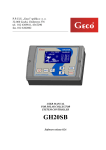
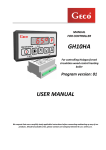
10. METHOD OF CONNECTING EQUIPMENT TO G-406-P02 CONTROLLER:
Mixing pump \
utility hot water
pump
Central heating
system
circulating pump
Power supply
220-230
AC
Fan
R
FUSE WTA5x203 15A
PPUH GECO Sp. Z o.o.
Cholerzyn 376, 32-060 Liszki, Polska
tel. +48 (12) 6369811 fax 6362002
www.geco.pl e-mail:[email protected]
Model: G-406-M12340T-P02
Date of Prod.: 12-06
Sn:0296
Un = 220-230 VAC Imax = 10A
P1 - Alarm
P2 - Mixing pump/HUW pump 1,5A 250W
P2 - Central heating pump
1,5A 250W
W - Fan
1,5A 250W
O-O Temperature limiter (STB)
Temperature sensor:
1-1 Inlet
2-2 Outlet
Temperature sensor
Temperature
Limiter (STB)
Water tank (HUW)
temperature
sensor
Outlet water
temperature
sensor of the boiler
Fig. 1 Diagram of connecting the equipment and detectors to the G-406-P02 controller.
PPUH „GECO” Sp. z o.o.
Issue I
as from the 2008-03-10
PAGE 14
G-406-P02 USER MANUAL
11. INFORMATION ON THE MARKING AND COLLECTION OF WORN
ELECTRIC AND ELECTRONIC EQUIPMENT
ATTENTION!
The symbol placed on the product or its packaging shows the selective
collection of the worn electric and electronic equipment. This means that
this product should not be disposed of together with other household
waste. The proper disposal of old and worn electric and electronic
equipment will help to avoid the potentially adverse results for the
environment and human health.
The selective collection of the worn equipment is the area of the
responsibility of the user, who should give this equipment back to the
collector of the worn equipment.
PPUH „GECO” Sp. z o.o.
Issue I
as from the 2008-03-10
PAGE 15
G-406-P02 USER MANUAL
12.
TROUBLESHOOTING GUIDE
Fault symptoms
1. The display fails to
illuminate in spite of
connecting the controller to
the network
2.
3.
4.
5.
6.
Items to check
Check:
• the presence of voltage 230V on the L and N supply terminals
• correctness of connecting the execution module with the control panel
• remove and reinsert band wire sockets
• connect another band wire
The fan fails to turn on in
Check:
spite of indication of its
• the presence of voltage 230V on the terminals according to the
activation - green diode
description on the upper wall of the execution module
• fan efficiency
• correctness of connecting the execution module with the control panel
• connect another band wire
The pump fails to turn on in Check:
spite of indication of its
• the presence of voltage 230V on the terminals according to the
activation - red, vertical
description on the upper wall of the execution module
dash
• pump efficiency
• correctness of connecting the execution module with the control panel
connect another band wire
Erroneous temperature
Check:
indication
• connection of the detector to the joint
• correctness of detector mounting
• state of detector cable; the cable may not have any damage
• carefully the appearance of the exterior surface of the detector scale, i.e
if it has not been damaged mechanically
• connect another band wire
“Abnormal” or “strange”
Check:
conduct of controller
• the presence of voltage 230V on the L and N supply terminals
• the condition of feeding joints
• the condition of wiring system and the number of equipment connected
to one phase
• if the control panel, execution module or band wire plugs have been
subjected to the operation of water or other liquid
• if the control panel, execution module or band wire plugs are exposed to
the operation of moist or violent temperature fluctuations
• correctness of connecting the execution module with the control panel
• connect another band wire
Display’s flickering, the
Check:
absence of activation
• the value of supply voltage
capability
• the condition of feeding joints
• securing the feeding joints
• correctness of connecting the execution module with the control panel
• connect another band wire
PPUH „GECO” Sp. z o.o.
Issue I
as from the 2008-03-10
P.P.U.H. “Geco” Sp. z o. o. [Ltd.]
Cholerzyn 376, 32-060 Liszki
ph. +48 12 6369811, 6361290
fax +48 12 6362002
http://www.geco.pl
e-mail: [email protected]