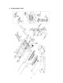
1
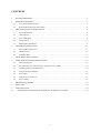
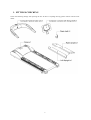
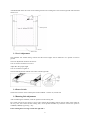
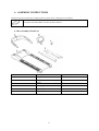
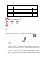
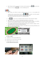
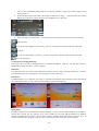
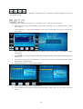
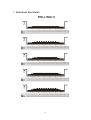
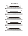
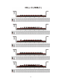
USER MANUAL – EN
IN 6923 Treadmill inSPORTline Borra Pro
1
CONTENTS
1.
FITTINGS CHECKING................................................................................................................................. 3
2.
OVERVIEW DRAWING .............................................................................................................................. 4
2.1
Wire Rod and Power Switch.................................................................................................................. 5
2.2
Running Belt and Lateral Incline Base .................................................................................................. 6
3.
IMPORTANT SAFETY INSTRUCTIONS ................................................................................................... 7
3.1
Power Requirement ............................................................................................................................... 7
3.2
Add Lubricant ........................................................................................................................................ 8
3.3
Level Adjustment .................................................................................................................................. 9
3.4
Power Switch ......................................................................................................................................... 9
3.5
Running Belt Adjustment ...................................................................................................................... 9
4.
ASSEMBLY INSTRUCTIONS ................................................................................................................... 11
4.1
Pre-Assembly Check List .................................................................................................................... 11
4.2
Hardware Pack..................................................................................................................................... 12
4.3
Assembly Steps ................................................................................................................................... 13
5.
PULSE DETECTION SYSTEM .................................................................................................................. 15
6.
COMPUTER OPERATION INSTRUCTIONS ........................................................................................... 16
6.1
Subject Instruction ............................................................................................................................... 16
6.2
Key Functions (Any effectively key should create one sound) ........................................................... 19
6.3
General Operation and Instructions: .................................................................................................... 20
6.4
Exercise Program Summary: ............................................................................................................... 21
6.5
Error Signal ......................................................................................................................................... 26
6.6
iPod Function Instructions ................................................................................................................... 26
6.7
Project Mode ....................................................................................................................................... 29
7.
PROGRAM DIAGRAMS ............................................................................................................................ 34
8.
PARTS LIST ................................................................................................................................................ 44
9.
EXPLODED VIEW ..................................................................................................................................... 49
10.
TERMS AND CONDITIONS OF WARRANTY, WARRANTY CLAIMS .......................................... 50
2
1. FITTINGS CHECKING
Check the following fittings after opening the box. If there is anything missing, please contact with the local
dealer.
3
2. OVERVIEW DRAWING
4
2.1 Wire Rod and Power Switch
Wire Rod:
Twist the power cord round the wire rod.
Note:
Don’t carry the treadmill by the wire rod. Pulling it by force will result in distortion.
Power Switch:
Circuit Breaker
If the current excesses rated current, the circuit breaker will bounce.
Press it back after 10 minutes.
Power Socket:
Please pay attention to the voltage of the socket (110V or 220V)
5
2.2 Running Belt and Lateral Incline Base
Running Belt:
Don’t touch the running belt by hand to avoid danger while the treadmill is running.
Lateral Incline Base:
The hand shouldn’t be close to the incline base to avoid danger while the treadmill is ascending or falling.
6
3. IMPORTANT SAFETY INSTRUCTIONS
When using this product, basic precautions should always be followed, including the following:
Please read the instruction carefully before starting to use this product.
Danger – To reduce the risk of electric shock:
:
Always unplug this product from the electrical outlet immediately after using and before cleaning the treadmill.
Warning – To reduce the risk of burns, fire, electric shock, or physical injury:
:
•
The product should never be left unattended while plugged in.
•
When using the treadmill, please step on the treadmill before start. Do not start the treadmill and then
step on the treadmill. Unplug the product from the outlet when not in use or before putting on or taking
off the clothes and other belongings.
•
To avoid any danger, close supervision is necessary when this production is used by children, invalids
or disabled persons. So it is when the machine is working with such persons around.
•
Not proper or excessive training may be harmful to your health.
•
Be sure to use the product only for its intended use as described in this manual. Do not use any
attachment not recommended by the manufacturer in order to avoid any danger or accidents
•
Never operate the product if it has a damaged cord or plug, if it is not working properly, if it has been
damaged, or dropped into water. Please return the product to the service center of seller for examination
and repair.
•
Do not carry this product by the supply cord or use the cord as a handle.
•
Keep the cord away from hot surfaces or ground.
•
Never operate the product with the air vents blocked. Keep the air vents free of lint, hair, etc.
•
Never drop or insert any objects into any vent of the treadmill.
•
Do not use or operate outdoors.
•
Place the treadmill on flat ground or flat roof.
•
Please confirm 2000mmx1000mm space away behind the treadmill.
•
Do not operate where aerosol (spray) products are being used or where oxygen is thin.
•
Before turning the product power off, turn all controls to the off position then remove the plug from the
outlet
•
Connect the product to a properly grounded outlet only.
•
If the machine has folding mechanism, user should descend the incline to original position after
workout.
•
The max weight of user is 150kg.
3.1 Power Requirement
Power Voltage (V)
Frequency (H)
Rated Current (A)
100
50/60
18
120
50/60
18
200
50/60
9
220
50/60
9
230
50/60
9
7
240+
50/60
9
Wirings should be transported according to the electric law of the local country. High pressure wires, low
pressure wires and underground wires should be transported separately and can’t connect with or twist other
wires.
Improper connection of the grounding plug can result in the risk of electric shock. Check with a qualified
electrician or serviceman if you are in doubt as to whether the products are properly grounded. Do not modify
the plug provided with the product – If it will not fit the outlet, have a proper outlet installed by a qualified
electrician.
3.2 Add Lubricant
Use the Hex Wrench to unscrew the hex screws inside the Rear End Cap. Then pull the belt up and daub some
SILICON to the center of the board. After that, adjust the belt to the center of the deck, followed by tightening
the screw to the original set. Half a month should be checked once.
•
Time of add SILICONE
When suggested time of adding SILICONE is achieved, please extend your hand to the center of the running
board to make sure whether there is any SILICONE before adding. If no SILICONE on the running board,
please add 30cc SILICONE to the running board. If there is still a little SILICONE, add 15cc SILICONE to the
running board.
•
Area of adding SILICONE
8
Add SILICONE from the center of the running board to the running belt’s the left and right side which should
minus 6 cm.
3.3 Level Adjustment
The treadmill will wobble during workout and the incline angles will be affected if it is placed on uneven
ground.
The level adjustment method is as follows:
Turn A counter-clockwise to loosen it
Adjust B to the proper height
Turn A clockwise to tighten it.
The left side adjustment method is the same with the right side.
3.4 Power Switch
The Power Switch is on the bottom panel of the treadmill. 1 means on, 0 means off.
3.5 Running Belt Adjustment
After assembling the treadmill, check the operation of the running belt.
First, make sure the power supply is correct. After starting the treadmill, stand on the two sides of the pedal (At
the very start, don’t stand on the running belt). Press QUICK START key and then increase the speed to
4.0MPH (6.4KPH) by pressing + key.
If the running belt is moving towards the right side:
:
9
Turn the right button 90°clockwise and contrarotate the left button (A) 90°. You will find the treadmill return to
the center position automatically.
If the running belt is moving towards the left side:
:
Turn the left button 90°clockwise and contrarotate the right button 90°. You can also find the treadmill return to
the center position automatically.
If you find that the belt has not moved to the proper position, please repeat the steps above.
Note:
:When adjusting the button, the angle cannot exceed 90°which will make it impossible to adjust the belt
to the proper position.
10
4. ASSEMBLY INSTRUCTIONS
Ready the operation instructions carefully before use, then choose a flat position to assemble.
This treadmill also can use other way to account the HRC. When in fitness, user can wear the
chest pulse belt and the HRC will show in Pulse windows.
4.1 Pre-Assembly Check List
ITEM
Description
Qty
A
Computer handrail tube set
1
B
Computer console with fixing shelf
1
C
Frame
1
D
Left upright tube
1
E
Right upright tube
1
F
Flask shelf
1
11
4.2 Hardware Pack
ITEM
Description
Qty
a
Allen bolt SK-470
8
b
Truss hex screw M8xP1.25x15
4
c
Hex head screw M8xP1.25x20
Stainless Steel
2
d
Washer Ø8xØ19x3.0t
2
e
Spring Washer M8
4
f
Truss hex screw M8xP1.25x30
2
g
Sucker
4
h
Bushing Wrench + Screwdriver
1
i
T-shaped Wrench 8mm x 200mm
1
j
Hex Wrench + Screwdriver
5mm x 70mm x 70mm
1
k
Hex Wrench 6mm x 80mm x
80mm
1
l
SILICONE
1
m
Safety clip
1
n
Philips screw M5xP0.8x15
2
12
4.3 Assembly Steps
STEP 1
Two persons are required to finish the assembly steps.
Caution!! Please follow exactly the assembly steps below to avoid injury.
Remove the motor cover from frame (C), then slightly fix Upright (D, E) with screw (a, c) and washer (d, e).
Note:
:
•
To avoid danger, always assemble the treadmill with more than two workers, do not assemble by
yourself.
•
When assembling the upright, make sure one person holds the upright to avoid falling.
STEP 2
1. Place the Computer Shelf (A) on the assembled Uprights (D, E) of Frame(C) and pull the control wire
in upright to connect it with the computer’s. Then put the computer shelf above the uprights and tighten
with Truss hex screw (b) as shown in the above drawing
13
2. Fastening Uprights (D, E) tightly on Frame (C). Finally, put the motor cover back to Frame (C) and
tighten it with Philips screws.
Note:
:
(1) When tightening the screws, pay attention whether the control wire in the tube is hooked or pressed.
(2) When connecting the control wires, pay attention whether the corresponding color is right, red matches with red
and white matches with white.
STEP 3
Put console that with fixing shelf (B) on computer handrail tube(A), then connect control wire, TV cable wire &
transferring board wire well by turn and put the extra wires in computer fixing shelf, put computer in handrail set
and fasten with screw(f) & spring washer(e).
STEP 4
Pot Holder assembly
Put Tea Pot Holder (F) on the Up Right Bar (E), secure the Bolt (n) inserted and fixed with fastening.
STEP 5
14
When you want to use I PAD, you can take out the sucker attached in parts package and stick it on the suitable
place of computer(as left figure), then put your I PAD on supporter and use sucker to suck up your I PAD to
avoid the I PAD falling down.
5. PULSE DETECTION SYSTEM
A. Hand Grip Sensor System
Put hands on the steel sensor of the front handrail to detect the pulse system during workout. Each handrail is
equipped with two sensors. You must grip these four sensors to catch the pulse signal during workout. After 20
to 30 seconds, the result will display.
When the speed is above 4.5mph (7.2KPH), you shouldn’t grip the sensor for stability but to use chest belt
pulse monitor.
B. Chest Belt Pulse Monitor
Pulse detection system includes chest belt pulse monitor which should be put electrode on the body. Remote
sensor technology is used to transmitted the pulse signals to control board. Chest belt is not the necessary
attachment. You can purchase if you need.
Figure: middle electrode position and wearing ways of chest belt
The above figure is middle electrode position and wearing ways of chest belt. Electrode A is on the center of the
chest belt’s inside groove. The electrode must be wet when using to make the pulse signals transmit to receiver
accurately.
Try to dress the chest belt under the chest muscle. Adjust the chest belt to comfortable position to keep breath
smooth. It is best to detect the pulse detection by touching the skin directly, but it also can achieve by dressing a
thin and wet clothing.
If you want to wet the electrode of the chest belt, hold the middle of the chest belt and pull it out to wet directly.
15
6. COMPUTER OPERATION INSTRUCTIONS
6.1 Subject Instruction
This computer is 10.1”TFT-LCD Window. Display functions include BPM, SPEED, DISTANCE, KCAL,
INCLINE, PACE, TIME, CHANNEL, VOLUME, PROGRAM figure.
1. SPEED/INCLINE/DISTANCE:Indicate the value of speed, inclination angle and distance during the
workout.
2. KCAL:Unit of calories consumption while workout(kcal).
3. PACE:Time need at current speed, the accumulation distance should reach 1KM(mile).
16
4. BPM:Unit of heart rate(times/min).
5. CHANNEL: Under digital TV mode, channel quantity will show on movie screen.
6. VOLUME:Display the volume under AV/ DTV/MP3 or iPod mode.
PROGRAM profile:
Goals mode: This program consists of Time, Distance and Calories goals to select.
programs mode:There are six exercise programs to choose, such as interval exercise program,
stable exercise program and so on.
Fitness test mode: This program is a 12 minutes fitness test.
HRC mode: Heartbeat exercise mode which has levels of 65%, 75%, 85% and THR. Set the
exercise levels in accordance with the coach or requirements of self-direction.
User mode: You can manually adjust the intensity during your workout, total 32 stages.
Race mode: You can race with console by distance or time entered.
During workout or under start/ready status, if unplug SAFETY KEY, the STOP (as the below picture) will pop
up in the center of the screen and then all of values will return ’0’. At that time, the treadmill and program
immediately stop, but incline stays where it is. To return to start-ready status, you can plug SAFETY KEY back
to emergency stop system.
1. Once insert SAFETY KEY back, the screen will require you to set weight kgs (lbs). You can press
or numerical keys for quick setting. Default value: 70kg (150lbs).Range: 23~180kg
(50~400 lbs). After complete setting, press
to return to start/ready status.
17
2. If you like to use the default settings, directly press
•
or
to return to start/ready status.
The purpose of setting weight is that built-in program calculates calorie burn based on weight, so you
are required to set your weight when re-start the treadmill or every time plug back the safety key.
3. During workout, if heart rate is not detected from the hand grip, the BPM window displays 0. When you
continuously grasp on the hand grip, the blinking heart figure appears on BPM window which means
measurement is taking place, then window displays heart rate reading within in 20 sec.
4. BPM value range is 40~220BPM. It can use both hand grip and wireless pulse and wireless signal is in
advance.
This computer has MP3 input/output function. User should plug MP3 PLAYER cable intoψ3.5input hole of
computer. Then music will output though the horn of the treadmill(Insert the earphone into earphone hole and
the music will output through earphone).
Insert the earphone into this hole and the music will output through earphone.
Plug MP3 PLAYER into this hole by using 3.5φ sound cable and then you can enjoy the music under
MP3 mode.
Use connective wire for this hole insert to iPod can change to iPod mode and use every functions of
iPod (include electrification)
18
6.2 Key Functions (Any effectively key should create one sound)
Under start/ready status, motor will with the lowest speed of 0.8 kph (0.5 mph) and the
incline automatically returns to 0%.
Under program control menu--motor will start with the preset value.
Press this key to stop the treadmill during your workout, and in the same time, to stop
counting for all of values. You can press this key to immediately return to the start/ready
status from any programs or setting you are in.
Press this key to increase speed during your workout.
Press this key to decrease speed during your workout.
Press this key to increase incline during your workout (Max. Level 15, Step 1)
Press this key to decrease incline during your workout (Min. Level 0, Step 1)
After starting the program, press this key to switch number instant key to adjust incline.
Press PAUSE key to pause the program and all the windows will stop counting. Press this
key again to start.
Adjust volume under DTV、AV、MP3 or iPod mode.
Under ”ON” state of multimedia mode, press this key to switch among DTV, AV, MP3 or
iPod mode(circularly)
Adjust channel under DTV mode.
After starting the program, press this key to switch number instant key to adjust speed.
This key is used as instant number input function under data setting state.
During workout, this key can be used as speed and incline instant key, range is 0-9 integral value, below
10KPH(MPH) or incline 10% is single code directly input, above 10KPH (MPH) or incline 10% is double code
combination input. For example: 21KPH, Press “2”once and then press “1”(determinant time is within 1 second).
19
1. ON:Touch this key to turn on multimedia function (DTV、AV、MP3 or iPod mode),press again to
turn off(OFF).
2. TV:Touch this key to switch among DTV、AV、MP3 mode (circularly)
3. START:Function as
4. STOP: Function as
key.
key.
5. MODE:Press this key to set 1-32 levels under USER mode.
6. ENTER:When setting parameters under program control mode, press this key to confirm.
7. +:When setting parameters under program control mode, press this key to increase value.
8. -:When setting parameters under program control mode, press this key to decrease value.
9. CLEAR:When setting parameters under program control mode, press this key to get back default
value and return to the first item or option menu.
•
You can touch center position of video area under TV, DTV, AV or IPOD-VIDEO mode to zoom in or
out screen.
6.3 General Operation and Instructions:
1. The program will be exercised based on the default weight 70kg (150lbs). Once you change the value.
(Range: 23~180kg/ 50~400lbs), program will be exercised according to the latest weight value.
2. Under start/ready status, touch the program you selected to enter into program profiles (Goal mode,
Programs mode, Fitness Test mode, HRC mode, USER mode, Race mode)
3. The guiding texts will be shown on the screen to guide you for the next setting step by step.
4. Under any setting screen, you can press
return to previous screen.
key to cancel editing, to revert to default setting or to
5. During your workout, setting values will count down until “0”, by the time, program is finished.
6. Under start/ready status, you can press
key to enter into manual run.
7. After starting the program, treadmill automatically adjusts the speed and incline in accordance with the
program.
8. During workout, press
key, then the treadmill and incline motor stop immediately.
9. Once program finishes or the time hits maximum value (99:59), warning sound will come up, and then
treadmill stops to “run end” status and the main motor stops and incline will not change.
10. During start/ready status if incline is not at LEVEL 0, press
to start treadmill, incline will automatically return to LEVEL 0.
key for 2 sec or press
key
11. When incline is returning to LEVEL 0, to unplug SAFETY KEY can stop the incline motor.
12. Program mode: After entering this mode, you can select programs(P1~P6)and then touch it directly
key to start and the rest unset parts will adopt default
to enter into the editing menu. Or press
value.
20
•
During level adjustment, bar chart displays INCLINE and SPEED in 1-32 stages. Press
to adjust the level intensity L1~L10 (Refer to attached pages).
•
The total workout time to run a PROGRAM is divided by 32 stages.
key
13. Under Pause state, program will be over after 1 minute, or during workout, press
key, the
count up value window will display and after 20 seconds, it will jump back to Start/Ready menu.(User
can press
key to directly leave the menu when the treadmill totally stops ).
6.4 Exercise Program Summary:
MANUAL Mode
1. Press
key, then start 3 seconds countdown, when finished, the motor starts at the speed of
0.8KPH(0.5MPH) and picture shows playground running withershins. The circle number will display at
the left corner of playground. Every circle is 0.4KM (0.25MIL). You can also touch the picture at the
lower left corner to switch to project picture mode.
2. Speed STEP is 0.1 KPH(MPH). Press speed +/- key to select or press
key 0~9 to select target value.
3. Incline STEP is 1, press incline +/- key to select or press
key and number instant
and number instant key 0~9 to select.
4. TIME window displays positive number and time reaches 99:59, then the treadmill will stop
automatically and return to start/ready mode.
21
5. Press
Key when motor is running, then the speed of motor will decrease to stop and the angle
of incline motor will not change. Center window will display ”PAUSE”. If press
key again, the
motor will restart and speed up slowly to the previous speed, incline maintains the preset height before
stop.
Goal mode
Time Goal:
:This program is to set the target workout time, once the goal is reached, treadmill stops
automatically.
Distance Goal:
:This program serves to test your endurance. Once distance is completed, treadmill stops
automatically.
Calories Goal:
:This program serves for weight control. Once goal calories are burned within a certain time,
treadmill stops automatically.
1. After entering, you can touch
parameter.
key or number instant key to adjust TIME、DIS or CAL
•
Time Range: 20~99 min, default value is 20 min, step is 1 min.
•
Distance Range:1~99km(mile),default value is 5km(mile),step is 1km(mile).
•
Calorie Range:40~999kcal,default value is 500kcal,step is 1kcal.
2. After setting values, press
key to start running program and time will countdown
3. When setting TIME, DIS or CAL parameter, if you want to cancel the previous parameter, press
key to turn to the first item to reset or press
key to return to Start/Ready menu.
4. After setting the target value, press
key or press
key during setting to start the program
(Unset parameter will adopt the preset value) and time will be executed by countdown.
5. During workout, press speed/incline +-key or number instant key to change speed and incline range.
Any target value of TIME, DIS or CAL parameter reaches 0, then the program is over.
Programs
1. After entering this mode, there are total six program for you to choose: Rolling、Fat
burn、Aerobic、Hill run、Hill climb and Hill intervals.
22
2. After sub-program is selected, press
levels of intensity.
key to adjust the workout level. There are total 10
3. After selected LEVEL, press
key, at this time you can press
(Default: 20 min, Range: 20-99min).
4. If you want to cancel the last parameter, you can press
press
key to adjust TIME
key to revert to the first item to reset or
key to return to start/ready status.
5. After setting the target time value, press
key or press
key to start the program during
setting(The unset sport intensity will adopt the preset value: Level 1). Time will be executed by
countdown.
6. During workout, press speed +-key and incline ↑↓ key to change speed and incline. There are total 8
levels to choose.
Fitness Test Mode
1. The program time is 12 minutes which is divided into 32 stages.
2. You are required to enter age (13~80) and sex. Program will be exercised based on your setting.
3. After finish setting values, press
key to start the program. During setting, you can also
press
key to start the program.(The unset parameter adopts the preset value) and time will be
executed by countdown.
4. Preset speed is 2.0 kph (1.2 mph)
5. Start running and just release speed +- key and don’t release incline↑↓ key and
key, for user
should run on the flat (0 level) slowly for 12 minutes to calculate the health value by the total exercise
distance.
6. When program is over, it will enter YOUR FITNESS TEST RESULT automatically. The window will
show the number from 1 to 5. 1 means the worst score and 5 means the best score.
7. FITNESS TEST mode comparison table:
-
If Distance is :”0”, the result will be “0”also.
MALE
AGE
DISTANCE
<20
<1.00
<1.25
<1.50
<1.75
≧1.75
<30
<1.00
<1.25
<1.50
<1.75
≧1.75
<40
<0.95
<1.15
<1.40
<1.65
≧1.65
<50
<0.85
<1.05
<1.30
<1.55
≧1.55
>=50
<0.80
<1.00
<1.25
<1.54
≧1.54
RESULT
1
2
3
4
5
23
FEMALE
AGE
DISTANCE
<20
<0.95
<1.15
<1.35
<1.65
≧1.65
<30
<0.95
<1.15
<1.35
<1.65
≧1.65
<40
<0.85
<1.05
<1.25
<1.55
≧1.55
<50
<0.25
<0.95
<1.15
<1.45
≧1.45
>=50
<0.65
<0.85
<1.05
<1.35
≧1.35
RESULT
1
2
3
4
5
HRC (need to wear wireless chest belt)
The purpose of this program is self-training based on heart rate. During the training, when heart rate of runner
achieves the setting number that you make, incline and speed will keep within a certain range for best training
effort
The whole heartbeat control program has total four target pulse 65%, 75%, 85% and THR (Target Heart Rate).
Calculate formula of heartbeat setting=(220-AGE)* heartbeat program control value
For example, age is 40,if the target pulse is 85%, then the heartbeat times:(220—40)×85%=153
1. When editing, user should set age(preset:30;range: 13-80). After setting, press
key to input
objective heartbeat value(default value will change with the age user input automatically) and exercise
time(pre-set: 20:00, editing range: 20~99min). Press
If you want to change the parameter, press
key to run the program.
key to turn to the first item to reset or press
key to return to Start/Ready menu
2. After starting HRC program, the treadmill is running with the speed of 1.6 KPH(1.0MPH), incline 0.
Every 10 seconds the program will increase or decrease speed according to the actual heartbeat value. If
heartbeat value is lower than the set heartbeat value, the speed will be increased by 0.5 KPH(0.3MPH).
If heartbeat value is higher, the speed will be decreased by 0.5 KPH(0.3MPH). If the speed increased
continuously for ten times, the incline will ascend by 1 step. If the speed decreased continuously for ten
times, the incline will descend by 1 step. The max speed can increase to upper limit. The min incline
can ascend to the fifteenth level.
3. When detecting no heartbeat value, NO PULSE will display. If no heartbeat is detected for 45 seconds,
the motor will stop and jump back to Start/Ready state.
The chart below will show the relationship between different age and heart rate of this treadmill of HRC
function.
24
BPM
BPM
Age
BPM
Age
H
Preset L
13
197
124
124
14
196
124
15
195
16
BPM
Age
H
Preset L
31
180
113
113
124
32
179
113
123
123
33
178
194
122
122
34
17
193
122
122
18
192
121
19
191
20
Age
H
Preset L
H
Preset L
49
162
103
103
67
145
92
92
113
50
162
102
102
68
144
91
91
112
112
51
161
101
101
69
143
91
91
177
112
112
52
160
101
101
70
143
90
90
35
176
111
111
53
159
100
100
71
142
90
89
121
36
175
110
110
54
158
100
100
72
141
90
89
121
121
37
174
110
110
55
157
99
99
73
140
90
88
190
120
120
38
173
109
109
56
156
98
98
74
139
90
88
21
189
119
119
39
172
109
109
57
155
98
98
75
138
90
87
22
188
119
119
40
171
108
108
58
154
97
97
76
137
90
86
23
187
118
118
41
170
107
107
59
153
97
97
77
136
90
86
24
186
118
118
42
169
107
107
60
152
96
96
78
135
90
85
25
185
117
117
43
168
106
106
61
151
95
95
79
134
90
85
26
184
116
116
44
167
106
106
62
150
95
95
80
133
90
84
27
183
116
116
45
166
105
105
63
149
94
94
28
182
115
115
46
165
104
104
64
148
94
94
29
181
115
115
47
164
104
104
65
147
93
93
30
181
114
114
48
163
103
103
66
146
92
92
User mode
1. After entering, press MODE key to edit the speed and incline value of 1~32 levels. You can press speed
+-key and incline↑↓ key to edit the speed and incline segment (1–15 segment)of each level. While
editing it, it will blink. Press
level setting.
User can also press
setting.
key into the next level setting or press
key to start at any
key with preset level 1 or last kept sport value to enter into time target value
2. After editing the sport intensity of 1~32 levels and start the program, if press speed +-key and incline↑↓
key, then conduct the second intensity change of 1~32 levels (1~32 levels will ascend together). The
ascend step is the upper limit value calculated by the highest value of 1~32 levels. For example, the
highest value of 1~32 level is set at the twelfth segment. After entering the program, press incline↑↓
key, then 1~32 levels will have 3 segment change.
3. Time preset value is 20 min(Range:20-99min). Every level time is that editing time divides 32.
4. Operation method of Pause and Stop is the same as Manual Run.
5. Speed preset value is speed upper limit value/20 and incline preset value is 1 segment.
25
6. While setting parameters, if you want to cancel the previous parameter, press
first item to reset or press
key to turn to the
key to return to Start/Ready menu.
Race
1. When editing, user should set objective distance (0.1、0.4、1.0、2.0、5.0、10.0 km/mile) and
key to adjust. At this time, program
estimate the time to finish the target value. Touch
will automatically calculate the Pacer Speed according to the edited number.
Pacer Speed=Target Distance/Target Time, unit is KM/HR(ML/HR).
2. Press
key to start, after 321 countdown and then user starts to throw-off with the computer.
3. When the input number is invalid, you should adjust the parameter to start this mode.
4. The blue point on the playground represents user and the red point represents computer. At the bottom
left corner of the playground will display how long the computer is ahead or behind user
5. User can adjust speed and incline by manual. When user(blue point) is behind the computer, increase
the treadmill speed to catch up with the computer(red point).
6. When one of the player finished the set distance, the treadmill will stop running automatically and
display the exercise cumulative number.
6.5 Error Signal
E1:Treadmill can’t read the speed feedback value.
E6:Incline motor can’t work within the ADC range.
E7:Incline is higher or lower (over range).
6.6 iPod Function Instructions
26
(1)Nike+iPod Exercise Function
After user connect iPod connective wire with iPod sets, right lower corner of screen’s Nike+iPod typeface will
change from silver to red color, it means under connection, when Nike+iPod turn from red to gold color means
successful connection (remark 1)
Press START or procedure controlling start, screen will show the individual training information that user set in
iPod sets, as ages, weight and so on, confirm and press ENTER.
When procedure controlling closed or user press STOP, screen will show user’s total exercise record on this time
and store in user’s IPOD sets
User can enter iPod to scan the exercise data just store (remark 2)
(2) iPod Mulit-media Functions
27
1. User can start multimedia during iPod sets connecting condition, original mp3 mode change to iPod
mode (remark 3)
2. iPod mode have music and videos total 2 kinds of functions for using, music functions can read the
MP3 music in iPod sets, videos functions can read MP4 movie in iPod sets.
3. After enter music or videos mode, it will auto show files read and user select this file then can play
Back to main list
Press for one time change to previous song,press for a long time can make the playing tempo back
Play/pause
Press for one time change to next song,press for a long time can make the playing tempo forward
Main list change line
(3) iPod Power Charging Functions
This product have 5V power charging functions of APPLE iPod\iPhone、iPad sets,the sets and computer’s
iPod handle windows will show “power charging”
Remark I:
:
User Nike iPod, the sets need to install Nike+iPod software and user need to examine whether set’s windows
have this function, if have, the machine’s record function can be normal used
Remark II:
:
If APPLE model or rev of software is not same, it will lead to the machine cannot examine exercise record from
sets, must connect iTune or Nike +iPod’s ACCA and then can see the storage data
Remark III:
:
This iPod connecter with manufacturers canonical terminal, it can be used for APPLE iPod all series, iPhone 3
period, iPad 1 period, but the protective cover sales in market are not same and the thickness are different
between manufacturers and generic. If user cannot connect smoothly, please take off the protective cover of
iPod, iPhone, iPad, then try again. If still not work, it means this product cannot use for this machine.
28
6.7 Project Mode
When you first use this computer, please enter into this mode to adjust TV system setting and other items are not
allowed to change by non-engineer.
Entering method: Under start/Ready mode, press
key once and then press
key at once.
Touch ”5TV setup” into next option
※DVBT Digital Setup Steps
1. DTV System:There are DVBT and ATSC system specs according to regions. Please switch to DVBT.
2. Press “5”to enter into DTV Setup.
3. After entering, it will display install menu, please switch cursor to DTV signal area and set the local
country.
※Key Instructions:
29
+/-key:Portrait item select key;ENTER:Confirmation key;CLEAR key:Cancel installation or return to
the last option menu.
CHANNEL↑/↓Key:Portrait item select key;VOLUME +/- key:Transverse item select key;
4. After setting the country, press ENTER key again and it will display ”Do you want to install?”,please
select ”Yes”0.
(If user selects No,it will cancel installation. If you want to install again, enter step 6 to get back the
preset value)
5. After selected Yes, it will automatically scan channels, when reaches 100%, it will jump to channel
review menu.
6. Press
mode.
key to exit project mode and then check whether the video and sound are normal under DTV
7. If you want to scan again, press PAUSE key on the left side of the key board under Database Empty
menu to enter into Main Menu.
8. After selected Digital TV menu, press ENTER key.
9. Select ”Factory Default” item, press ENTER key.
10. ”Enter password” will display and please input password ’’0000’’ (Press “0” four times on the key
board).
30
11. Then ”Do you want to perform factory default?” will display, choose Yes.
12. Repeat step 3.
P.S. You can just change Factory Default of Main Menu and the rest can’t be changed.
31
E7 incline function malfunction trouble shooting :
Remove Safety key and then insert back it, incline motor will calibrate automatically and return to normal ADC
value after several seconds.
If problem still can’t be solved, press STOP key to enter into start/ready mode.
Press ENTER key and don’t release it, then press MODE key to enter into configuration mode.
After entering into configuration mode, first press number key”1”, then press number key”5” to enter into the
window of incline parameter.
Please write down the value of Incline AD max and Incline AD min, then press ”clear” key to return to the first
page.
Press number key”3” to enter into Fitness testing mode. Please check whether the number of “Incline Level” is
within the +-3 range of the step(3). If value is over or the treadmill is at the high position(as picture 1), please
press incline↓ key; On the contrary, if the value is lower or the treadmill is at low position(as picture 2), please
press incline↑ key.
Press incline↑or↓key and incline motor will return to 0 level. When value returns to the range and incline
motor stops, press stop to exit.
Restart program or manual run, at this time incline motor will return to the original position. Please make sure
whether incline is normal or not.
If you have tried the above steps and still can’t solve the malfunction of incline function, please contact with
technology repairer of your dealer.
32
(Picture 1)
(Picture 2)
E6 incline function malfunction trouble shooting
1. Please remove the motor cover in front of the running board. Check whether the power cord and signal
wire of the incline motor are off or not.(Please refer to Fig E1 B-b).
2. Restart the treadmill and run it. When check incline ↑↓ key, make sure whether L1 or L2 light of
controller is light or not. If is, check whether the incline mechanism of the treadmill is locked or replace
the motor. If isn’t, check whether the wires of the computer and the controller are off or not, if the wires
are normal, please replace the controller or the computer.
3. If the above steps still can’t solve the malfunction, please contact with technology repairer of your
dealer.
33
7. PROGRAM DIAGRAMS
34
35
36
37
38
39
40
41
AEROBIC
42
FAT BURN
43
8. PARTS LIST
NO
item no.
Description
q'ty
needed
/set
1
HTF229FE-C
computer console
1
3
SOC8
nylon nut M8xP1.25
10
4-1
RD-25-001
film keyboard 25 keys
1
4A
BAE0300-300-10
rubber pad 30mmx30mmx1.0t single side tape black
1
5
JTFD002
computer shelf w/ handrail tube assembly
1
5-1
SDA8-15
truss hex screw M8xP1.25x15
4
6-1
P-3182
hand grip pulse plastic base
2
6-2
NO-4994
hand grip pulse sensor plate(steel)
4
6-3
RBA-040
handrail switch sticker(angle)
1
6-4
RBA-039
handrail switch sticker(speed)
1
8
XL-1239
handrail switch + lower hand grip wire
2
9
SCI5-15
round head philips self-tapping screw Φ5x15
7
10
XEK-284
transferring board
1
11
SAI3-8
round head philips self-tapping screw ø3x8
4
12
HTZ004
transparent sucker set
1
14
P-3185
upper handrail cover
1
15
P-3186
lower handrail cover
1
16
SCI4-16
round head philips self-tapping screw ø4x16
18
16A
SAM4-16
round head drill philips self-tapping screw ø4x16
2
17A
NT-771
water bottle holder
1
18
HTFC002L
PU handrail (L)
1
18-1
P-3180L
handrail tube sleeve cover L
1
18-2
SCI4-10
truss philips self-tapping screwΦ4x10
10
Note:
PU handrail set must be bought with(18-1)*1 (32)*1(18-2)*5
19
HTFC002R
PU handrail (R)
1
19-1
P-3180R
handrail tube sleeve cover R
1
Note:
PU handrail set(21) must be bought with (19-1)*1 (32)*1(18-2)*5
20
P-3183D
upper computer cover
1
21
XL-1249A
transferring board connecting wire upper
1
22
XL-1259B
transferring board connecting wire lower
1
23
XL-1237
handrail switch +upper hand grip wire
2
24
SPA050-100-20
flat washer ψ5Xψ10X2.0t
2
25
SAE5-10
round head philips screw(cutted end) M5xP0.8x10
2
27
SDA8-15I
truss hex screw M8xP1.25x15
4
44
28
SDA8-30I
truss hex screw M8xP1.25x30
2
29
SHA6-12N
counter sink philips screw M6XP1.0X12(ni)
3
32
SAK3-8
round head philips self-tapping screw(flat end ø3x8
20
34
XL-1251
middle control wire 24#12C (2x6)
1
35
XL-1250
upper control wire 24#12C (2x6)
1
36
XL-836B
lower control wire 24#12C (2x6)
1
38
XEK-028-260
hand grip pulse board
1
40
SCE5-10
truss philips screw(cutted end) M5xP0.8x10
6
41
XHB-RE06 5K
Wireless Pulse Receiver
1
XL-RE06
POLAR Receiver
1
BAC0200-200-30
Double Sided Tape 20mmx20mmx3.0t
1
42
XL-1242
film keyboard transferring wire
1
44
P-3184
Lower Computer Cover – Ve schématu to není kabel, ale zadní
kryt ovládacího panelu
1
47
XEM-016
Safety Switch Set
1
48
HTHA003
Safety Key set
1
51
JTCA073
Upright Assembly(Left)
1
52
JTCB066
Upright Assembly(Right)
1
53
SK-470
Truss Hex Screw
8
55
P-2299
Motor Cover
1
56
NO-4151
Motor Cover Fixing Plate
6
57
SCE5-15
Truss Philips Screw M5xP0.8x15
18
58
BAA0700-400-50
Foam Sticker 70mmx40mmx5t
2
59
XM-186
Incline Motor
1
GH-058-004
Shaft Φ12XΦ10X12mm – VE SCHÉMATU JE 2X – PRO 2
RŮZNÉ DÍLÝ
2
60
SGA10-50I
CKS Hex Screw M10xP1.5x50
1
61
SOC10
Nylon Nut M10xP1.5
6
61A
SOC10-8T
Nylon Nut M10xP1.5x8t
1
62
XM-230B
A.C Motor
1
63
P-1685
Isolation Pad(Upper)
4
64
P-1686
Isolation Pad(Lower)
4
65
SGA10-25I
CKS Hex Screw M10xP1.5x25
4
66
SPA100-200-30
Flat Washer ø10xø20x3t
4
67
SPB10
Spring Washer M10
6
68
CA-240J10A
Drive Flex Belt
1
69
SGA8-95I
CKS Hex Screw M8xP1.25x95
1
70
SOA8
Hex Nut M8xP1.25
1
71
P-1853
Adjustment Screw Cover
1
45
72
SPA030-080-05
Washer ø3xø8x0.5t
1
74
SAA5-10GZ
Round Head Philips Screw M5xP0.8x10 (Galvanization)
5
78
SAE5-12
Round Head Philips Screw M5xP0.8x12
4
79
P-1720
Plastic Washer
2
81
XEB-009
Filter
1
82
BAE-001
Rubber Pad
4
84A
XRB-023-017C
Transducer (2.0Hp,220V) RM5LDH
1
Note:
Transducer must be bought with
Wire *1
XLT027,XLT029
Extension
85
XEH-003-001
Power Cord Socket
1
86
XEA-A001
Power Switch
1
87
XLZ-TM
Power Cord
1
88
P-1825
Power Cord Switch Cover
1
89
SCE4-10
Truss Philips Screw M4xP0.7x10
22
90
XEG-10-001
Circuit Breaker
1
91
NT-1636
Power Cord Collector
1
92A
HTAD001
Sensor set 1050mm
1
95
PEC-UC-2
Wire Clip Knob
2
96
PEC-UC-3
Wire Clip Knob
1
97
P-1301
Fixing Cushion
6
98
MB-027
Running Board
1
Note:
(98) running board must be bought with (202)*2 (203)*3
99
NO-4401
Running Board Extension Plate
2
100
JTFA047
computer shelf assembly
1
102
BAA14400-24050
foam sticker 1440mmx24mmx5t single side tape black
2
103
SIA8-35I
Counter Sink Hex Screw M8xP1.25x35
6
104
SIA8-40I
Counter Sink Hex Screw M8xP1.25x40
4
105
P-2505
Plastic Pedal
2
(105) must be bought with (107),Pedal must be bought 2pcs for
one time
Note:
106
XEJ-T35X23
Iron Core Ring
1
107
P-2296A
Pedal Decoration Strip Single Sided Tape
2
BAC9100-920-05
Double Sided Tape 910mmx92mmx0.5t Black
2
108
SAK4-10
Round Head Philips Self Tapping Screw ø4x10
8
109
NAL-070
Pedal Fixing Plate
8
110
SEA8-115-25
Allen Bolt M8xP1.25x115 25mm
8
111
P-2340L
Rear End Cap(Left)
1
112
P-2340R
Rear End Cap(Right)
1
46
114
P-1927
Assistant Wheel
2
116
T4B003E00095
Bushing ø10.5xø15.8x9.5(Post)
2
117
SGA10-35I
CKS Hex Screw M10xP1.5x35
2
118
CB00041
Running Belt
1
119
NRL-005E
Front Roller
1
120
SGA10-100I
CKS Hex Screw M10xP1.5x100
1
121A
SPA100-200-10
Flat Washer ø10xø20x2t
1
122
SPD10
Inner Toothed Washer M10
1
123
SOA10
Hex Nut M10xP1.5
1
124
XLT044
Extension Wire(Kelly)14AWGx450x2R
1
125
NRL-005F
Rear Roller
1
126A
SGA10-80I
CKS Hex Screw M10xP1.5x80
2
127
NO-3475
Baffle
1
129
SPB5
Spring Washer M5
4
130
SCE5-12
Truss Philips Screw M5xP0.8x12
6
131
PN-001-12
Adjustment Foot Pad
2
132
JTBC012
Incline Base Assembly
1
133
NT-1000A
Incline Base Fixing Base
2
134
SGA8-30I
CKS Hex Screw M8xP1.25x30
4
135
SPB8
Spring Washer M8
16
136
P-1037
Plastic Sleevelet
2
137
P-1789
Wheel
2
138
SGC10-70-35I
CKS Hex Screw M10xP1.5x70 35mm
3
139
JTAA039
Frame Assembly
1
140
XLT002
Extension Wire(White) 14AWGx90x2t
1
141
XLT001
Extension Wire(Black) 14AWGx90x2t
2
142
XLT067
Extension Wire(Kelly) 14AWGx400x1T1R (R end is inner toothed
+T end is mother end)
1
143
XEN-008
Choke
1
144
XLT047
Extension Wire(Kelly)14AWGx500x2R (R end is inner toothed)
1
152
RCA-004
computer decal
1
152A
RCA-001
Computer Panel Decal left
1
152B
RCA-002
Computer Panel Decal right
1
153
SSB8-200
T-shaped Wrench 8mmx200mm Ball Head Heat Treatment
1
154
SSA6-80-80M
Hex Wrench 6m x80mmx80mm
1
154A
SSH5-70-70M
allen wrench+screw driver 5mmx70mmx70mm
1
155
SK-433A
Sleeve Spanner + Screwdriver
1
156
BD-001-100
Bottled Silicon
1
159
SPA080-200-20
Washer ø8xø20x2t
8
47
165
XLT032
Extension Wire(White) 14AWGx450x2t
1
167
XHA-T34
Chest Belt Pulse Emitter POLAR T34
1
168
PEC-UC-0.5
Wire Clip Knob
3
169
SEA8-20I
Allen Bolt M8xP1.25x20
2
170
SPA080-190-30
Washer ø8xø19x3.0t
2
171
XLT027
Extension Wire(White) 14AWGx260x2t
1
172
XLT029
Extension Wire(Black) 14AWGx260x2t
1
175
XL-955B
TV Cable set(lower) (RG-6/U)
1
176
XEL-10-002
10.1"TFT-LCD digit panel (contain touch screen)
1
177
BAA0150-165-10
Foam Sticker 15mmx165mmx1.0t
2
178
XL-931
Touch screen Connecting Wire
1
179
NO-5635
LCD fixed slice 10"
1
180
SAA2-3
Round Head Philips Screw M2xP0.4x3
6
181
XRA-090-004
Upper Control CT-100-I
1
182
SAA3-4
Round Head Philips Screw M3xP0.5x4
8
185
XEK-059
MP3 Sound Cable
1
189
XL-1263A
TV Cable set(upper)
1
192
XEK-198
Earphone Socket
1
193
XL-938
Earphone Socket Connecting Wire
1
196
XEK-197
AV Extension board+wire
1
197
XL-1059
AV Extension board through connection wire
1
202
RBA-013
Grounding sticker (Aluminum with single side tape)20x1440L
2
203
RBA-014
Grounding sticker (Aluminum with single side tape)20x670L
3
212
XL-935
digit tuner board Connecting Wire(DVB)
1
213
XL-1304
digit tuner board Control Wire
1
214
XL-1081A
I-Pod Control Wire upper
1
215
XL-1081C
I-Pod Control Wire lower
1
216
XL-1270
Middle TV cable wire
1
48
9. EXPLODED VIEW
49
10.TERMS AND CONDITIONS OF WARRANTY, WARRANTY
CLAIMS
General Conditions of Warranty and Definition of Terms
All Warranty Conditions stated hereunder determine Warranty Coverage and Warranty Claim Procedure.
Conditions of Warranty and Warranty Claims are governed by Act No. 40/1964 Coll. Civil Code, Act No.
513/1991 Coll., Commercial Code, and Act No. 634/1992 Coll., Consumer Protection Act, as amended, also in
cases that are not specified by these Warranty rules.
The seller is SEVEN SPORT s.r.o. with its registered office in Borivojova Street 35/878, Prague 13000,
Company Registration Number: 26847264, registered in the Trade Register at Regional Court in Prague, Section
C, Insert No. 116888.
According to valid legal regulations it depends whether the Buyer is the End Customer or not.
“The Buyer who is the End Costumer” or simply the “End Costumer” is the legal entity that does not conclude
and execute the Contract in order to run or promote his own trade or business activities.
“The Buyer who is not the End Customer” is a Businessman that buys Goods or uses services for the purpose of
using the Goods or services for his own business activities. The Buyer conforms to the General Purchase
Agreement and business conditions to the extent specified in the Commercial Code.
These Conditions of Warranty and Warranty Claims are an integral part of every Purchase Agreement made
between the Seller and the Buyer. All Warranty Conditions are valid and binding, unless otherwise specified in
the Purchase Agreement, in the Amendment to this Contract or in another written agreement.
Warranty Conditions
Warranty Period
The Seller provides the Buyer a 24 months Warranty for Goods Quality, unless otherwise specified in the
Certificate of Warranty, Invoice, Bill of Delivery or other documents related to the Goods. The legal warranty
period provided to the Consumer is not affected.
By the Warranty for Goods Quality, the Seller guarantees that the delivered Goods shall be, for a certain period
of time, suitable for regular or contracted use, and that the Goods shall maintain its regular or contracted
features.
The Warranty does not cover defects resulting from:
User’s fault, i.e. product damage caused by unqualified repair work, improper assembly, insufficient insertion of
seat post into frame, insufficient tightening of pedals and cranks
Improper maintenance
Mechanical damages
Regular use (e.g. wearing out of rubber and plastic parts, joints etc.)
Unavoidable event, natural disaster
Adjustments made by unqualified person
Improper maintenance, improper placement, damages caused by low or high temperature, water, inappropriate
pressure, shocks, intentional changes in design or construction etc.
Warranty Claim Procedure
The Buyer is obliged to check the Goods delivered by the Seller immediately after taking the responsibility for
the Goods and its damages, i.e. immediately after its delivery. The Buyer must check the Goods so that he
discovers all the defects that can be discovered by such check.
When making a Warranty Claim the Buyer is obliged, on request of the Seller, to prove the purchase and validity
of the claim by the Invoice or Bill of Delivery that includes the product’s serial number, or eventually by the
documents without the serial number. If the Buyer does not prove the validity of the Warranty Claim by these
documents, the Seller has the right to reject the Warranty Claim.
50
If the Buyer gives notice of a defect that is not covered by the Warranty (e.g. in the case that the Warranty
Conditions were not fulfilled or in the case of reporting the defect by mistake etc.), the Seller is eligible to
require a compensation for all the costs arising from the repair. The cost shall be calculated according to the
valid price list of services and transport costs.
If the Seller finds out (by testing) that the product is not damaged, the Warranty Claim is not accepted. The
Seller reserves the right to claim a compensation for costs arising from the false Warranty Claim.
In case the Buyer makes a claim about the Goods that is legally covered by the Warranty provided by the Seller,
the Seller shall fix the reported defects by means of repair or by the exchange of the damaged part or product for
a new one. Based on the agreement of the Buyer, the Seller has the right to exchange the defected Goods for a
fully compatible Goods of the same or better technical characteristics. The Seller is entitled to choose the form of
the Warranty Claim Procedures described in this paragraph.
The Seller shall settle the Warranty Claim within 30 days after the delivery of the defective Goods, unless a
longer period has been agreed upon. The day when the repaired or exchanged Goods is handed over to the Buyer
is considered to be the day of the Warranty Claim settlement. When the Seller is not able to settle the Warranty
Claim within the agreed period due to the specific nature of the Goods defect, he and the Buyer shall make an
agreement about an alternative solution. In case such agreement is not made, the Seller is obliged to provide the
Buyer with a financial compensation in the form of a refund.
SEVEN SPORT, s.r.o.
Borivojova 35/878 130 00 Praha 3, Czech Rebublic
CRN: 268 47 264, VAT ID: CZ26847264
Orders:
+420 556 300 970,
[email protected]
Warranty Claims:
+420 556 770 190, Mobile: +420 604 853 019,
[email protected]
Service:
+420 556 770 190, Mobile: +420 604 853 019,
[email protected]
Fax:
+420 556 770 192, (Service +420 556 770 191)
Web:
www.insportline.cz, www.worker.cz, www.worker-moto.cz
INSPORTLINE, s.r.o.
Bratislavska 36, 911 05 Trencin, Slovakia
CRN: 36311723, VAT ID: SK2020177082
Orders:
+421(0)326 526 701, +421(0)917 649 192,
[email protected]
Warranty Claims:
+421(0)326 526 701, +421(0)918 408 519,
[email protected]
Fax:
+421(0)326 526 705
Web:
www.insportline.sk, www.worker.sk, www.worker-moto.sk
Date of Sale:
Stamp and Signature of Seller:
51