1
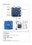
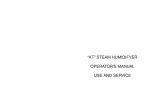
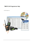
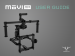
Smoooth Operator
Gimbal Controller
User Manual v1.2
Disclaimer
For whom the controller is intended?
If you fly multicopter or other RC model, if you have an experience in pilotage, if you can make
correct movie, without vibrations etc, if you have patience to read the manual, if you can solve
technical problems alone - this controller is for you.
It helps to improve the quality of movies offering many additional features like camera shutter
control, switching signals from several video cameras etc.
For whom the controller is not intended?
If you are beginner pilot and have a problem with pilotage, your movies are full of vibration and
shocks, you can't operate your model smoothly, don't have the basic skills modeler, you don't know
how the Tx/Rx (BEC, servo etc) is working, you don't have the patience to read the manual like this this product probably is not intended for you.
Remember, that our controller isn't "ready to fly" - before using it, it's necessary to read the manual
and to spend some time setting the proper parameters of the controller.
If you don't have enough time or patience, DON'T BUY IT!
What we DO NOT promise
We don't promise a magic.
This controller is the electronic system, not a magic wand. If your movies are full of vibration and you
can't operate your model smoothly, movies done with gimbal and controller will be probably even
worse.
Support
As producer, we don't offer direct technical support by phone, Skype, e-mail etc.
If you have any problems look for the solution in the manual, or discussion forum. Last if you can't
solve the problem feel free to write to us - if that problem really exist we will try to write the solution
in our FAQ.
Except for exceptional cases we are not able to answer individual e-mails with request for technical
help.
Warranty
We guarantee that controller works as manual described for 3 months from the date of purchase.
Failure that occurred during this period of time we will repair at our own expense. In case of any
damages done by the user (for example because of wrong connections etc) we can try to diagnose
and repair at cost of parts and labor. If controller is completely destroyed we can replace board with
the new one at 1/3 of the stock price (we don't cover parcel cost in that case).
Specifications and designs are subject to be changed without prior notice for further improvement.
Trademarks and product names used herein are for identification purposes only and may be
trademarks of their respective companies.
Thank you for purchasing of our controller. We hope, you will be satisfied and you will enjoy using it.
Before you start of using gimbal's controller you should read this manual first. If you don't
understand it, try to read it again or ask for advice more experienced friends or you can also use
discussion forum like RC groups. Internet is endless source of information - if you have a problem
someone for sure will help you solve it.
Please remember to respect someone else's time, so first read the manual, then eventually ask for
help if you are still confused.
Introduction
Smoooth Operator is an advanced electronic device designed to stabilize camera gimbals with up to
three axes. It has built-in presets for the major types of gimbals available on the market (e.g.
Cinestar, Photohigher, Photoshipone).
Moreover, stabilization algorithm can be tuned via the configuration program to suit almost all
gimbals, including hand-made ones.
All axes can be controlled manually with the standard RC receiver using normal or rate mode.
In the normal mode inclination angle is directly proportional to the stick position while in the rate
mode stick position determines angle change rate. Roll axis can be controlled in ±40° range and
tilt/pan (pitch/yaw) in ±360° range which means can perform continuous rotation.
Additionally, controller is packed with a bunch of extended features like infrared trigger, video
switch, electric relay and more.
All of them are handled and can be tweaked by the configuration tool (hereinafter called the
configurator).
Basics:
•
external IMU (3-axis MEMS gyro and accelerometer)
•
8 PWM outputs (50/100/200/400Hz selectable)
•
4 PWM inputs (8 channels in PPM mode)
•
3 to 1 video switch (high speed, low glitch switching)
•
infrared trigger (experimental learning capability)
•
reed relay (galvanic isolation, high speed)
Hardware
Technically speaking, controller board is manufactured in Europe with the use of fully automated
production line so the risk of possible failure is significantly reduced.
Controller hardware with the main parts marked is presented on the following pictures.
External IMU
To calculate camera position controller uses external sensor (called IMU) consisting of 3-axis gyro and
accelerometer which can be placed directly on the camera plate (so called advanced mode) or just on
the gimbal frame (aka simple mode).
IMU module is a very sensitive device and has to be placed in a possibly vibration free area and away
from any sources of radiation (transmitters etc.). Ideally, in the advanced mode sensor board should
be mounted near the center of the camera plate which in most cases means just under the camera.
Of course, you have to check if wires between IMU and the controller are not limiting gimbal
movements and are free from entanglement.
Luckily, there are many supported module orientations as described in the Select IMU placement
paragraph.
Due to sensor temperature drift it is strongly recommended to leave controller on for a few minutes
in the flight environment and then restart the controller to perform gyro startup calibration again.
PWM outputs
Controller is equipped with eight PWM (Pulse Width Modulation) outputs so it can drive up to the
eight servos. Six of them are directly driven by the stabilization algorithm (two for each axis) and the
last two are auxiliary and can be assigned to the input channels with the configurator.
Very important thing is to understand that due to the high demand on current of modern servos
PWM outputs are not powered by the controller itself. Therefore, external voltage regulator must be
used and connected to the PWM out voltage pins (center and bottom) to supply the servos. You have
to choose your regulator wisely, keeping in mind one digital servo can draw several ampers
dependent of the load.
External voltage should be in 5-10V range but if higher than 5V (for faster/more torque servo
operation) you should double-check if all connected servos support that.
PWM inputs
There are four PWM inputs on the controller so you can connect maximum number of four receiver
channels to control gimbal movements and extended features. If you need more channels you have
to use receiver with the composite PPM (Pulse Position Modulation) output which should be
connected to the input line #4. Doing this, you are enabling controller to use all eight channels
encoded in the PPM frame.
By default, there is no voltage on the middle pin of each input connector in case you are powering
your receiver from the external source. Otherwise, you can feed middle pin with 5V from the
internal, controller’s regulator using jumper as shown below. In that case you must be aware though
that current draw on the input pins should not exceed 100mA in sum.
Be aware to remove the radio power jumper in case you connect external voltage to the middle pin.
Video switch
Controller is equipped with the video switching capability which means you can connect up to three
video sources (e.g. two small FPV cameras looking straight and downwards plus the main camera)
and send selected one to the operator with the use of external video transmitter.
Additionally, one of the inputs is designed such way you can directly plug-in standard FPV camera
and it will be powered by the controller itself. Be aware though, that pin is directly connected to the
main power connector so its voltage will be the same as the input voltage (in 7-20 V range).
Infrared trigger
Assuming your camera can be operated with the infrared remote you can use gimbal controller to
mimic its functionality and for example send command to take a picture, start/stop recording or
zoom in/out. To achieve that optional infrared transmitter must be connected to the IR port.
Configurator contains list of supported cameras&functions and will be gradually updated by the
internet update function. What's more, controller can learn new infrared commands but we cannot
guarantee it will work with every remote control unit. You can initiate learning process from within
configuration tool after connecting IR receiver to the PWM input pin #1.
Electric switch
Controller is equipped with the reed relay that is galvanically isolated from the controller circuits so
can handle relatively high voltage and current (max 250V and 1A).
Relay can open/close its circuit controlled by the input channel’s data after doing appropriate
assignment in the configurator.
Status leds
There are several leds on the controller board to signal status of the major components.
Thus, there is a yellow main power led, yellow PWM outputs power led, bi-color USB connection
transmit/receive (RX/TX) led and finally red and green controller status leds.
As of the controller status leds its outputs are duplicated to the external pins to allow connection of
the bigger and more visible ones (one bi-color or two separate leds).
Meaning of the status led colors as follows:
•
•
•
•
•
constant green – controller is working properly.
slow blinking green – controller or servos voltages are below constraints set in the
configurator. Refer to the documentation of Miscellaneous tab.
fast blinking red – sensors are calibrating. Very important thing is to not move sensors during
this process, otherwise calculated angles may not be accurate and can drift.
slow blinking red – some sensor’s I2C bus errors occurred. Check if IMU’s wire is properly
connected and no external interferences exist (e.g. strong electromagnetic field).
constant red – controller program is halted due to serious hardware error. If problem persist
contact customer service.
More status leds color combinations can be found in the Troubleshooting paragraph.
Configurator
To initialize Smoooth Controller and setup for use with your rig you have to run configuration tool
aka configurator. It is very straightforward application, written in Java so in general can be run on
most operating systems that supports its native serial communication library (Windows, Linux, Mac).
For now it was only tested on Microsoft Windows 2000/XP/7 though.
Configurator has no installer so it only needs to be unpacked from the archive and run using one of
the dedicated executables. After application windows appears just connect the controller with your
computer using supplied USB cable and hit Connect. Controller RX/TX and sensor calibration leds
should blink during connection is made and after that Inputs tab should open. Remember not to
move sensor plate while calibration led is blinking, otherwise stabilization angles can drift.
Warning: do not connect any servos at this time, just IMU and USB cable.
After initial setup is done and controller is correctly configured to work with your gimbal you don’t
have to disconnect power from the servos to connect to the configurator. Furthermore, all changes
made in the configurator are instantly transferred to the controller and activated. Though, do not
forget to save changes permanently using SAVE SETTINGS button before disconnecting.
If any configurator error occurs its details should be written in the application’s “log” folder so you
can send files from there to the manufacturer for debugging purposes.
Overall
Main window consists of the menu bar, the central workplace area and the bottom, status bar.
Menu bar has the following options:
File -> Connect – opens Connect window
File -> Disconnect – disconnects from the controller
File -> Import – imports all controller settings from file (all current values will be lost)
File -> Export – exports all controller settings to file (profiles are not exported)
File -> Exit – exits configurator
Tools -> Reset settings – resets all settings of the controller to the default
Tools -> IMU placement – opens Select IMU placement window
Tools -> Update software – opens Update components window
Tools -> Reflash controller – opens Reflash controller window (Windows only)
Tools -> Check for update – verifies if controller or configurator update is available on connect
Tools -> Check for presets – verifies if Mechanics tab presets update is available on connect
Tools -> Check for cameras – verifies if camera’s infrared codes update is available on connect
Help -> About – you know what ;)
Workplace area contains tabbed panels where functions that allow to tweak particular settings of the
controller are grouped by type.
Content of the tabs are described in the next paragraphs.
Status bar consists of information block and the SAVE SETTINGS button.
Information block displays version of the controller’s firmware and messages that are results of
executing particular actions of the configurator (errors are marked red).
SAVE SETTINGS button saves all changes made to the controller in its persistent memory so has to be
used before disconnecting if you want them to last after controller’s restart.
Connect
Before opening this window you should connect the controller and wait some time till the computer
recognizes it and installs its communication port. After that you can select appropriate port and hit
Connect button.
In case of the connection error you can check if add extra wait time function helps or retry using
another USB port. If there are no available ports on the list verify if port is visible in the system device
manager and if so look for errors in the application’s “log” folder.
Important thing to note is that during connection is being made sensor calibration occurs, the same
way as during normal power up (if startup calibration is selected). Thus, you should not move IMU
plate till connection window closes itself or disable startup calibration on the Miscellaneous tab.
Select IMU placement
IMU placement window is available only after the controller is connected to the configurator and is
designed to define the actual placement of the IMU board.
Mounting type field is very important and configures the controller to use simple (frame) or
advanced (plate) mode for the roll and tilt axes stabilization.
In the simple mode, where IMU has to be fixed to the gimbal frame (its not-moving part) only
proportionals for roll&tilt axes have to be set (refer to the Tuning tab paragraph). In the advanced
mode (aka plate) PID loops are responsible for roll&tilt stabilization so proper values are to be set for
these axes at the Mechanics tab. Pan axis requires PID tuning for both mounting types.
Horizontal arrow describes if board has normal or inverted position and vertical arrow means which
way sensor wires go.
Very important thing is to disconnect power from servos or at least disable stabilization on all axes
before changing placement’s settings to avoid abnormal gimbal behavior.
Update components
Using this window you can internet update some parts of the configurator application in case any
update is available from the provider. Version check occurs while the connection to the controller is
being made and if a new version is available or version check fails relevant information is shown on
the bottom status bar. You can read about the changes in the latest version by placing the cursor
over the product line.
After update is completed you have to restart the configurator and in case new Firmware was
downloaded update the controller manually using Tools->Reflash controller function.
Reflash controller
After new version of the firmware is downloaded by the Update software function you can upload it
to the controller using this window.
We are sorry, but for now that function works only on Microsoft Windows.
Inputs tab
Inputs tab is directly related to the controller’s PWM inputs and displays values for all available input
channels.
In case of using PPM signal (refer to the PWM inputs paragraph) you have all, eight channels active
and only four otherwise.
Input -> Invert – inverts input value
Input -> Trim – adds/subtracts selected amount from the input value (in microseconds)
Input -> Smooth – smoothes input value by the selected factor
PPM – controls PPM support on Input 4 (disable in case of problems with the ordinary PWM)
Deadband – introduces a deadband to the channel reading to eliminate noise (in microseconds)
Overwrite – allows to manually overwrite input values by moving the sliders
Calibrate – opens Calibrate inputs window
Calibrate inputs
Calibrate function should be activated if you want controller to know actual ranges and middle values
of the input channels. Namely, at the first run and every time you change radio or its settings.
Before doing calibration you should reset all radio settings (e.g. trims, expos, ranges) to the default.
Calibration process is done in two steps. At first, channel ranges are determined so you have to move
all regulators from min to max position while progress bar is visible. In the second step input readings
boundaries are corrected in case middle input value is not exactly in the half way of the min and max
position. Correction is made only if deviation is small so you don’t have to center knobs etc.
After calibration end changes have to be saved manually using SAVE SETTINGS button.
Outputs tab
Outputs tab gives you direct view on the PWM output servos values (refer to the PWM outputs
section). It means each slider shows signal level that is being currently send to the corresponding
servo.
Output -> Invert – inverts output value (servo will move in the opposite direction)
Output -> Min – minimum output value that is allowed (in microseconds)
Output -> Max – maximum output value that is allowed (in microseconds)
Output -> Trim – trim for the middle output value (in microseconds)
Output -> Refresh – refresh rate for the PWM signal (higher means better but servo must support it)
Overwrite - allows to manually overwrite output values by moving the sliders
Test – opens Servo test window (only for servos with pots)
Servo test
Servo test window lets you check if your servos are moving smoothly in their full range which means
from the defined by the configurator min to max value.
Very important thing to note is that function will only work properly with the servos that have
internal or external pot connected so for example pan axis servo will be probably not suitable.
Assignment tab
Content of this tab is related to the controller PWM inputs that can be configured at the Inputs tab.
Here, you can assign input channels to change inclination of each axis and to control all, additional
features controller provides.
Roll/Tilt/Pan
If you want to alter camera plate inclination using your RC regulators you must assign appropriate
inputs to the angles that are to be changed.
Primary thing to consider is whether you will use normal or rate mode to control each angle.
In the normal mode current angle directly corresponds to the regulator’s position in range specified
by the value of the Max angle field (+/- field value). For example, if the regulator is in middle position
you will always get neutral angle. If max angle is set to 40 and you’ll move your regulator to the min
position corresponding angle is set to -40 degrees from neutral. Similarly, for max regulator position
angle will be set to +40 degrees from neutral.
In the rate mode by holding regulator off from neutral position you will be constantly adding or
subtracting some amount of degrees to the current angle. Rate of the angle change is proportional to
the regulator’s position and the value of Rate factor field. Though, max angle constrain (Max angle
field) is still valid so you cannot exceed its value. As you see in the rate mode middle regulator’s
position does not mean neutral angle but just not to change angle at all.
Do not forget to properly calibrate your radio using the Inputs->Calibrate function before doing
assignment if you haven’t done it before.
Note, that axis movements are coordinated by the same algorithms as the main stabilization so if you
can not achieve satisfactory results it may be required to modify settings at the Mechanics and/or
Tuning tab.
Input field – selects input that will be assigned to that axis
Max angle – sets max angle for the input control
Rate mode – sets angle change behavior
Rate factor – sets amount of angle change in rate mode
AUX
This module lets you assign input channels to move auxiliary servos at PWM outputs #7 and #8.
If inputs are calibrated properly (Inputs tab) whole range of the regulator should correspond to the
full servo range set on the Outputs tab with min and max values. If you want to reverse servo
movement just Invert assigned channel or appropriate output.
Servo 1 – selects input that will be assigned to the output #7
Servo 2 – selects input that will be assigned to the output #8
Profile
This, very important feature lets you assign input channel to switch between configuration profiles
created at the Tuning tab. Thus, you can simply change gimbal behavior e.g. its dynamic, trim angles
or just enable/disable stabilization during flight.
To use that feature just select adequate profiles in the subsequent fields that correspond to the input
channel’s low, mid or high states.
Profile named *default* means no custom profile was selected and controller is using base settings.
Important thing to note is that function does not work if configurator is connected to the controller.
Input field – selects input that will be assigned to switch profiles
Low – selects profile that will be assigned to the input’s LOW state
Mid – selects profile that will be assigned to the input’s MID state
High – selects profile that will be assigned to the input’s HIGH state
Video
You can utilize video feature in case you have connected up to three video sources to the controller
and want to switch between them.
To use that feature just select adequate video inputs in the subsequent fields that correspond to the
input channel’s low, mid or high states.
Input named *disabled* means video output is disabled (blank).
Technical aspects of the video switch function are described in the Video switch section.
Input field – selects input that will be assigned to switch video inputs
Low – selects video input that will be assigned to the input’s LOW state
Mid – selects video input that will be assigned to the input’s MID state
High – selects video input that will be assigned to the input’s HIGH state
Trigger
Assuming you own infrared transmitter diode and the camera that is capable of receiving commands
from the IR remote you can use that panel to assign commands to the input channel’s low or high
state. Therefore, you can trigger up to two, separate functions on your camera.
To use that feature just select adequate commands in the subsequent fields that correspond to the
input channel’s low or high states.
You can also configure the behavior in case trigger state is hold for some time with the Interval field.
Moreover, there is also an experimental function that enables the controller to learn new infrared
sequences from the existing remote. To do that you have to select the *NEW* option from the
cameras list (last one).
Technical aspects of the infrared function are described in the Infrared trigger section.
Note, that direct sunlight can “blind” IR receiver module in the camera so it may not respond to the
command send by the controller.
Input field – selects input that will be assigned to trigger infrared
Interval – sets activity interval in seconds if trigger state hold (set 0 for continuous and 99 for single)
Low – selects command that will be assigned to the input’s LOW state
High – selects command that will be assigned to the input’s HIGH state
Learn IR sequence
Learn IR window can be opened from the Trigger or Panorama cameras list.
It is an experimental feature so you must understand we cannot guarantee it will work in every case.
First thing you have to do is to prepare IR receiver unit and connect it to the PWM input pin #1.
In the scenario where IR carrier is modulated with frequency in 33 to 56Khz range (as in most IR
remote controllers) receiver schematic is relatively simple and costless.
Unfortunately, there are also remotes where carrier is not modulated at all (e.g. Canon) and you
have to use plain IR photodiode and some amplifier to handle that.
Note, that infrared trigger function supports only sequences where carrier is modulated with
33/36/38/40/56Khz frequency or not modulated (constant).
You also have to remember that the new IR sequence definition (and the whole cameras list) is held
in the application folder not the controller.
Learn – executes IR learning function
Try – sends received IR sequence to try whether it is working (active only after sequence received)
Save – adds IR sequence to the cameras list (active only after sequence received)
Frequency – selects carrier frequency for the transmission (visible only after sequence received)
Name – sets name for the new camera (visible only after sequence received)
Panorama
By using this feature you can automate making panorama photos or just simple 360 degrees look
around effects while filming.
Ordinary panorama mode is chosen if you select appropriate IR sequence in the Camera field.
If this mode is activated by holding appropriate input state gimbal will move on the pan axis by the
angle specified with the Factor field value. After desired angle is reached controller will send IR
sequence to make the photo, wait for some time and then move on to the next angle unless full
circle is made.
Remember to use short exposure times (sometimes needs higher ISO sensitivity) and manual focus
set to infinite (aka Landscape scene) for best aerial photos experience.
Movie panorama mode is chosen if you leave Camera field blank.
In this mode gimbal will do full circle with the speed specified by the Factor field value.
Note, that you have to hold activation state during the whole process unless function will be
interrupted and gimbal will return immediately to its initial position.
Pan axis stabilization must not be disabled using PWM off type for the panorama function to work. Be
aware though, that if other disabled type is set it will be automatically reset by the Panorama mode
and therefore Pan stabilization must be configured and working properly.
Input field – selects input that will be assigned to activate panorama
Camera – selects IR sequence that will be executed after angle reached
Factor – sets angle in degrees between photos or rate of rotation if camera is not selected
Low – if checked panorama will be activated if LOW state is held
Mid – if checked panorama will be activated if MID state is held
High – if checked panorama will be activated if HIGH state is held
Switch
To use that feature you have to assign required input and select which states will close the relay.
If you want to hold closed state for some time after input is released you can configure that using the
Hold field.
Technical aspects of the switch function are described in the Electric switch section.
Input field – selects input that will be assigned to activate switch
Hold – time in seconds to hold closed state after channel is released
Low – if checked relay will be activated if LOW state is set
Mid – if checked relay will be activated if MID state is set
High – if checked relay will be activated if HIGH state is set
Tuning tab
Tuning tab allows you to tune gimbal behavior and additionally create some custom sets of settings
and save them in a numerous profiles. Furthermore, up to three profiles can be assigned to the input
channel and switched whilst in midair. That way you can for example change gimbal responsiveness,
disable stabilization or change trim angle without the need for connecting the configurator.
In the simple mode, where IMU is fixed to the gimbal frame (refer to the Select IMU placement
paragraph) Proportional values are to be experimentally set for the roll and tilt axes to achieve best
hold of the horizon.
It is highly advised that you should start with the frame mode first.
Using the advanced mode (IMU at the camera plate) you must first ensure right PID’s are configured
on the Mechanics tab and stabilization is at least roughly working before starting the fine tuning
process.
Profiles group lets you create, switch and finally remove profiles which simply are the named sets of
settings from the Roll, Tilt and Pan panels. To create new profile just set all settings as desired and
click Create button. Then, name field will appear where you have to input unique name for your
profile and finally push Save button. The same button you will have to use in case you are going to
update your profile’s configuration. Remember, that after you modify profile which is already
assigned to the input channel you have to use global SAVE SETTINGS button to make changes
persistent in the controller also.
Profile named *default* means no custom profile was selected and controller is using base settings.
You have to be aware though, that profile list is stored locally that is in the folder where configurator
application is placed. That means may not be visible after you connect the controller to the different
instance of the application.
Using tuning panels for the roll, tilt and pan axes you can modify simple mode’s proportional factor,
base inclination of the gimbal plate, disable stabilization and at least fine tune the way controller will
respond to the gimbal movements. Fine tuning is a very subtle process and often has to be done in
case of the new camera model, weather conditions or even flight style changes. Fortunately, it is
often enough to change only Agressivity setting but in some cases there is also a need to modify PID
variables on the Mechanics tab (advanced mode only or pan axis).
To perfectly refine tuning settings you can use Infligtor mode that allows you to modify Aggressivity,
Smoothing and Sensitivity factors from your radio during flight. Such function is available at the
Miscelanous tab (refer to the Miscellaneous tab section).
Profiles -> Profile List – selects current profile
Profiles -> Create – displays the new profile Name field
Profiles -> Name – defines name for the new profile (must be unique or profile will be replaced)
Profiles -> Save – creates/updates profile configuration
Profiles -> Remove – deletes current profile from the list
Axis -> Proportional – horizon hold factor (simple mode only - IMU on the gimbal frame)
* 0 means no stabilization
* negative value means inverted response
Axis -> Trim base level – changes base plate position (in degrees)
Axis -> Stab. disabled – disables stabilization when selected using specific Disabled Types
Axis -> Aggressivity – scales response from the stabilization algorithm
* higher value means more aggressive response to the angle deviation
* too high value can cause instability and oscillation particularly for rapid shifts
* in case you are maxed out set to 50% and try to retune you PID values
Axis -> Smoothing – applies smoothing filter for stabilization algorithm
* higher value means more filtering and more fluent response
* too high value can cause instability and oscillation particularly for rapid shifts
Axis -> Sensitivity – sets algorithm sensitivity for small angle changes
* higher value means higher sensitivity and possibly better response resolution
* higher sensitivity will need servos with better resolution and lower deadband
* higher sensitivity will need gimbals with better precision and higher gear rate
* too high value can cause permanent servo play and jittering
Axis -> Speed – limits maximum angle change rate aka stabilization speed
* can be used if you don’t want fast transitions
Disabled types are as follows:
PWM off – turns off PWM on both servos (most servos will move freely)
Servo middle – sets both servos to middle (+/- Outputs trim)
Input tilt 1 – Servo middle plus assigned Input response limited to 10% range
Input tilt 2 – Servo middle plus assigned Input response limited to 50% range
Input tilt 3 – Servo middle plus assigned Input response in 100% range
Input rate 1 – Servo middle plus assigned Input response in Rate mode limited to 10% range
Input rate 2 – Servo middle plus assigned Input response in Rate mode limited to 10% range
Input rate 3 – Servo middle plus assigned Input response in Rate mode in 100% range
Stabilization is working only if Stab. disabled field is blank (no option set).
Mechanics tab
Functionality of this tab is very important when using advanced mode (refer to the Select IMU
placement paragraph) or pan axis stabilization and has direct impact on the stabilization loop output
and thus on the behavior of your gimbal. Luckily, in most cases such configuration is required only
once for each setup since further tuning can be made using the Tuning tab.
If you own one of the gimbals listed in the Gimbal model field it can be enough to select it and use
presets that were prepared by the controller’s manufacturer itself. List of the gimbals will be
gradually updated by the internet update function to handle new models.
In case your gimbal is not present on the list you can still use presets from the Preset field to set
coarse configuration for every axis and then adjust PID parameters experimentally to achieve best
performance.
Before changing PID configuration it’s recommended to revert all changes on the Tuning tab to the
defaults which means set Aggressivity to 40%, Smooth to 0%, Sensitivity to 90% and Speed to 100%.
Remember to be very careful during manual tuning and keep PWM outputs power connector nearby
to depower the servos in case of major instability.
There is always a risk that despite many efforts and extensive PIDs tuning you will not achieve
satisfactory results. In that case you will have to rethink your gimbal’s construction and for example
change servos to faster models with more torque, less deadband and better resolution or even
modify axes gears. Eventually, you should try simple stabilization mode (refer to the Select IMU
placement paragraph).
Finally, a few words about the stabilization algorithms that are available via the Algorithm field.
Basically, there are three, major types of them (A, B and C) where each one has P factor calculated
other way. Consequently, algorithms with the D suffix have slightly modified D factor calculation.
General type A is the most “aggressive” one and can usually be applied only if servo with internal or
external pot is used. Moreover, for the higher gear ratios servo has to be very fast and with enough
torque to quickly respond to the change of its PWM steering input. Practically, for that type only the
P and D factors are to be changed during tuning.
Types B and C are more universal and should work even if type A cannot be setup to work without
oscillations. For this algorithms P and I factors play major role and it is often enough to modify them
and leave D factor default.
Generally, at first always try to modify P factor leaving remaining parameters at the default levels for
the given type of the preset. Then, you can proceed to the next factor, that is D for the A algorithm or
I for the B and C algorithms. Usually, you will have to return to the P factor after that and repeat
whole sequence some more times to fine tune axis behavior.
For servos without potentiometers you can enable Center aligned checkbox to inform the controller
to not increment axis outputs by the value returned from the PID algorithm but rather add that value
to the outputs middle position.
To perfectly refine PID settings you can use Infligtor mode that allows you to modify PID parameters
from your radio during flight. Such function is available at the Miscelanous tab (refer to the
Miscellaneous tab section).
Gimbal Model – selects preset for the particular gimbal model
Axis -> Preset – selects preset for the particular gear type
Axis -> Algorithm – selects stabilization algorithm to use
Axis -> P – proportional part of the stabilization algorithm
Axis -> I – integral part of the stabilization algorithm
Axis -> D – derivative part of the stabilization algorithm
Axis -> Maximum I – maximum value of the integrated error (due to I factor)
Axis -> Center aligned – if checked outputs are not incremented (for servos without pots)
Roll and Tilt panels are disabled if mounting type is set to frame at the Select IMU placement window
(simple stabilization mode).
Miscellaneous tab
Miscellaneous tab lets you configure three, separate groups of the controller’s functions.
Sensors group can be used to configure sensor reading filtering properties, change startup calibration
procedures and at last run instant calibration routines.
You may want to raise sensors filtering levels in case IMU board is exposed to high frequency
vibration and stabilization behaves abnormally. Otherwise, you should set Gyro and Accel filter field
value possibly low to achieve maximum gimbal responsiveness (lower value means less filtering and
quicker response). Be aware that too high value can cause angles drifting and improper stabilization.
Dynamic filtering algorithm can be activated in case you prefer aggressive style of flying and noticed
that gimbal levels are getting fuzzy.
Zero gyro readings checkbox is active by default what means every time you power on the controller
or connect it to the configurator gyro sensor's zero level will be calibrated (red led will blink). Thus,
you cannot move IMU board and the whole gimbal till controller will fully initialize. If you don’t want
to be concerned about motionless startup deactivate that option. You must be aware though, gyros
are very sensitive devices and calculated angles can drift if not properly calibrated. You can also
enable startup calibration for roll and tilt axis using Zero roll&tilt levels fields but doing this you
enable controller to hold roll and tilt levels that are set on the startup (advanced mode only).
You can also instantly reset gyro zero and accelerometer levels using the Instant calibration panel.
Note that due to sensor temperature drift it is strongly recommended to leave controller on for a few
minutes in the flight environment and then restart the controller to perform gyro startup calibration
once again.
Voltages group allows you to monitor controller’s voltages and additionally configure low voltage
battery protection.
Minimum voltages constrains can be set using Controller min and Servos min inputs. Whenever one
of these voltages will drop below minimum green led will start to blink and disabled types will be
activated. If Disabled types are not selected stabilization will continue working.
Inflightor group enables you to perform gimbal behavior tuning during flight.
To set it up you must choose axis you want to tune using Tuned axis field, assign input channels to
modify selected properties (properties group can be switched with the Tuned tab field) and set Min
and Max values to limit available ranges. Lastly, select input that will Save modified values if selected
channel State is triggered.
To run controller in the Inflightor mode you have to toggle Activation button, save settings and
restart the controller after disconnecting by depower/power sequence.
To simplify tuning process you can simply connect Remzibi OSD (ARDUv1.73 firmware) to the
controller’s communication port (TX/RX/GND) and that way you will see values handled by the
Infligtor right on the screen.
For security reasons all other inputs assignments (at the Assignment tab) will be disabled after
Infligtor is activated.
Sensors -> Gyro filter – selects level of the internal gyro filtering
Sensors -> Accel filter – selects level of the internal accelerometer filtering
Sensors -> Dynamic filtering – enables dynamic filtering algorithm
Sensors -> Zero gyro readings – enables gyro startup calibration
Sensors -> Zero roll&tilt levels – enables accelerometer base roll and tilt levels startup calibration
Sensors -> Gyro zero readings – opens Calibrate gyro window
Sensors -> Accelerometer levels – opens Calibrate accel window
Sensors -> Temperature compensation – opens Temperature compensation window
Voltages -> Controller – displays controller main voltage
Voltages -> Servos – displays servos input voltage
Voltages -> Controller min – defines controller voltage under which controller will use Disabled types
Voltages -> Servos min – defines servos voltage level under which controller will use Disabled types
Voltages -> Roll disabled – selects disabled type for the roll axis in case voltage is below minimum
Voltages -> Tilt disabled – selects disabled type for the tilt axis in case voltage is below minimum
Voltages -> Pan disabled – selects disabled type for the pan axis in case voltage is below minimum
Inflightor -> Activation – activates inflightor function
Inflightor -> Tuned axis – selects axis to modify
Inflightor -> Tuned tab – selects group of parameters to modify (source tab)
Inflightor -> Aggressivity – selects input to use for Aggressivity factor modification
Inflightor -> Smoothing – selects input to use for Smoothing factor modification
Inflightor -> Sensitivity – selects input to use for Sensitivity factor modification
Inflightor -> Factor P – selects input to use for P factor modification
Inflightor -> Factor I – selects input to use for I factor modification
Inflightor -> Factor D – selects input to use for D factor modification
Inflightor -> Save – selects input to save modified values to the persistent memory
Inflightor -> State – defines input state to trigger Save function
Calibrate gyro
Allows instant gyro calibration.
Gimbal plate with the IMU board does not have to be leveled to perform calibration but must not be
moved during that process.
After calibration is done all changes to the controller are saved automatically.
Calibrate accel
Allows instant accelerometer roll and tilt base levels calibration.
Gimbal plate with the IMU board has to be leveled to perform calibration and must not be moved
during that process.
After calibration is done all changes to the controller are saved automatically.
Note that this function sets horizon only in the advanced mode, in the simple mode you have to
refine horizon using trims at the Tuning or Outputs tabs.
Note that Roll and Tilt trims at the Tuning tab are reset during level calibration.
Temperature compensation
Compensation window lets you calibrate IMU sensor to compensate angles temperature drift which
is especially noticeable in the below zero conditions.
Before final calibration you should perform a few IMU freeze-heat cycles (best done in -20°C ÷ 40°C
range) to smooth out sensor readings.
Next, cool down IMU module to the temperature below -10°C (-20°C recommended), place it in the
horizontal position, connect to the controller and hit Calibrate button. Remember to not move the
sensor during the whole process. At first let the IMU to heat up slowly but when the temperature is
over 20°C you can use an external heat source (such as lamp) to warm it up to the final 35°C.
If you get Temperature out of range message after you connect frozen (to below -20°C) IMU module
just wait until the temperature increases to start calibration.
Note, that the calibration data is stored in the controller and valid only for one IMU module so if you
change the module you have to recalibrate.
Calibration data is erased after you reset the controller using Reset settings menu function.
Controller tab
The Controller tab lets you control some major functions of the device without the need to assign
them to the input channels using the Assignment tab. What’s more, current assignments are
disabled when this tab is open.
Using the Movements group you can configure the way mouse motion will transfer to the gimbal
movement. Thus, you can set gimbal axis for the Horizontal and Vertical mouse shift and also the
axis which will correspond to the mouse Wheel scroll. For each axis smooth factor (second field) can
be applied as well to make gimbal movements more fluid. Wheel setup has the additional field added
to specify amount of axis inclination change for one wheel step.
To start controlling gimbal movement using a mouse you have to left-click on the center of the small,
black box placed in the middle of the controller pad. The magenta dot and the pink bar are indicating
real horizontal, vertical and wheel inputs position which are calculated using corresponding smooth
factors.
Note, that stabilization disabled types on the Tuning tab must allow gimbal to move similarly as in
the normal operation mode.
Features group allows to instantly call some of the controller’s features, namely, change one of the
assigned profiles, switch to one of the assigned inputs, trigger infrared sequence for LOW or HIGH
states and close in-build relay switch.
What’s more, you can even assign shortcut keys to the listed functions by placing the cursor over the
current shortcut key in the rectangular brackets and pressing alternate one on the keyboard. Finally,
using select fields in the last column you can define mouse buttons that will trigger selected
functions.
Both, shortcuts and mouse buttons will work only if controller pad is active which means after leftclick on the center of the controller pad. You can deactivate controller pad and release mouse cursor
by pressing “X” button on the keyboard.
If you want to maintain activation state for the longer time just hold the appropriate key/button for
more than two seconds and then release it.
Movements -> Axis – selects axis bound to the mouse function
Movements -> Smooth – sets smooth factor for given function
Movements -> Wheel amount – sets move amount for the one wheel step
Features -> Profile – selects active profile from the assigned ones
Features -> Video – selects active video input from the assigned ones
Features -> Trigger L – triggers infrared sequence assigned to the LOW state
Features -> Trigger H – triggers infrared sequence assigned to the HIGH state
Features -> Switch – activates reed relay
Monitor tab
Monitor tab displays live output from the gyro and accelerometer sensors.
Thus, you can monitor whether they are working and returning reasonable values.
For your convenience you can even select the graphs you want to show and change its scale using
Axis zoom field.
Charts group – selects group of charts to display
Chart selector – selects individual charts to display
Axis zoom – scale factor for displayed charts
Initialization
After unboxing the controller you have to gently connect it with the sensor board and plug to the
computer using supplied mini USB cable. Then, onboard leds should start to blink and the operating
system will install FTDI drivers to make the new communication port (COM) available.
After that, you should unpack configuration program to the folder where it can be easily accessible.
We recommend doing this on the removable drive e.g. pendrive to make switching to other
computers simpler (remember, that some controller’s configuration data is stored directly in the
application folder).
Finally, run the program and make connection to the controller active by clicking the Connect button
and selecting appropriate communication port. To verify if sensors are working properly switch to
the Monitor tab and make sure all graphs are changing their values when moving the sensor board.
After initial testing is done unplug the USB cable and install the controller at the gimbal frame.
For now, it will be enough to fasten the sensor board at the camera plate and connect all servos to
their output pins. Ideally, IMU board should be placed somewhere near the middle of the plate (e.g.
just below the camera) and of course in one of the supported positions (consult External IMU
paragraph for more information). Roll axis servo has to be connected to the output pin #1, tilt axis
servo to the output pin #3 and optionally pan servo to #5.
Very important thing is not to power the servos until it will be clearly written to do so!
After everything is firmly fixed connect the controller to the configurator, select your current IMU
board orientation using the Select IMU placement window and save changes with the SAVE
SETTINGS button. We are strongly suggesting that you should start with the frame mode (IMU sensor
set on the frame) because its setup is simple and gives very good results (note, that this mode works
only for servos with internal or external pots).
If there already exists prepared settings file for your gimbal you have to import it using the
File->Import menu item and all desired options should be set automatically.
Otherwise, you have to configure initial settings manually.
Configuration is dependent on the gimbal model and mode you are going to use.
Frame mode
At first you have to be sure your servos have internal or external potentiometers connected to use
that mode, otherwise use plate mode.
You can now carefully connect power to the servos line and enable roll stabilization at the Tuning
tab by selecting first, empty item on the Stab. disabled list. Next, move gimbal in the roll axis and at
the same time change Proportional field value for that axis to compensate movement.
At last enable stabilization for the tilt axis and set suitable proportional value.
Now, you can modify Aggressivity settings for both axes to fine tune gimbal behavior.
Plate mode
Start from the Mechanics tab where you can select the model your gimbal is similar to or just choose
single preset for every axis. Then, go to the Tuning tab and disable all axes, first one (Roll in that
case) with the Servo middle setting and the other two with the PWM off.
Now, switch to the Outputs tab and carefully connect power to the servos line. In case you are using
servo without internal or external pot you must ensure it is not moving at all at this stage. Otherwise,
modify Trim value for the first output (Roll #1) to find the real servo center at which the servo is not
rotating.
If everything is ok at this stage you are ready to enable stabilization for the first axis but before doing
this disconnect servos power for security reasons. Then, go to the Tuning tab and select first, empty
item on the Stab. disabled list for roll axis and return to the Outputs tab.
Now, you can carefully power the servos but if roll axis (and the corresponding output slider) will
immediately start to run in one direction without any sight of stabilization you have to quickly
depower the servos to avoid mechanical damages. In that case you have to enable Invert checkbox
for #1 output to revert servo direction and try to power the servos once again.
After stabilization is roughly working for the first axis you should switch to the Mechanics tab and
tune PID’s values to achieve best result (refer to the Mechanics tab paragraph).
Finally, repeat above steps for the other axes and refine the stabilization with the Tuning tab.
At the end you can connect your RC receiver, Calibrate it and assign to the appropriate features.
Troubleshooting
Problem
configurator did not start
could not connect to controller
Possible cause
Action needed
Java 1.6 or later not installed
install Java JRE 1.6 or later
operating system problem
check error log files in the “log” folder
FTDI drivers not installed
verify if new COM port is visible after controller is
connected with the supplied USB cable
serial connection library error
operating system problem
manually install FTDI drivers
check error log files in the “log” folder
green status led is blinking
voltages constrains reached
examine Miscellaneous->Voltages section
red status led is blinking
sensor communication errors
check sensor cable
move nearby transmitters away
restart the controller
green status led is on
red status led is on
performance issues
check sensor cable
restart the controller
contact manufacturer
green status led is off
red status led is on
serious hardware failure
restart the controller
contact manufacturer
servos are not moving
no enough voltage
PWM outputs disabled
verify if enough voltage is supplied
examine Outputs->Stab. disabled fields
stabilization behaves abnormally
sensor calibration inaccurate
incorrect IMU placement set
sensor communication errors
examine Tools->IMU placement window
calibrate sensor once again
move nearby transmitters away
restart the controller
gimbal plate is off the horizon
accelerometer not calibrated
incorrect angle trims
incorrect output trims
calibrate levels at Miscellaneous->Sensors tab
correct angle trims at Tuning tab
correct output trims at Outputs tab
angles are drifting
gyro not calibrated properly
sensor temperature drift
enable startup gyro calibration Miscellaneous>Sensors tab if disabled
do not move gimbal plate during statup
enable Temperature compensation
everything is wrong ;)
inconsistent or wrong settings
reset all controller’s settings to the default
using Tools->Reset settings menu item
Specification
Controller
Input voltage
7V ÷ 20V (onboard regulator may got hot if above 12V)
Working current
110mA
Dimensions
85mm x 48mm x 12mm
Weight
25g
Operating temperature
-10°C ÷ 50°C
Sensor
Input voltage
5V
Working current
10mA
Dimensions
35mm x 35mm x 15mm
Weight
15g
Operating temperature
-10°C ÷ 50°C
Features
PWM inputs
50Hz refresh rate, PWM/PPM automatic switching
PWM outputs
50/100/200/400Hz switchable refresh rates
Video switch
75Ω inputs/output, high speed, low glitch
Infrared trigger
33/36/38/40/56Khz and constant carrier rates supported
Reed relay
max 1A/250VDC
Angle accuracy
max ±0.01°, user selectable
roll axis: ±40°
Controlled range
tilt axis: ±360° (continuous rotation)
pan axis: ±360° (continuous rotation)