1
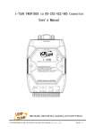
GWGW-7552
7552 PROFIBUS/MODBUS
PROFIBUS/MODBUS GATEWAY
User's Manual
High Quality, Industrial Data Acquisition, and Control Products
GW-7552 PROFIBUS/MODBUS GATEWAY User Manual (Version 1.00, Mar/2008)
PAGE: 1
Warranty
All products manufactured by ICP DAS are under warranty regarding
defective materials for a period of one year from the date of delivery to the
original purchaser.
Warning
ICP DAS assumes no liability for damages resulting from the use of this
product. ICP DAS reserves the right to change this manual at any time
without notice. The information furnished by ICP DAS is believed to be
accurate and reliable. However, no responsibility is assumed by ICP DAS
for its use, or for any infringements of patents or other right of third parties
resulting from its use.
Copyright
Copyright 2008 by ICP DAS. All rights are reserved.
Trademark
The names used for identification only may be registered trademarks of
their respective companies.
List of Revision
Date
2008/03/27
Author
Raiden
Version
1.00
Revision
Release
GW-7552 PROFIBUS/MODBUS GATEWAY User Manual (Version 1.00, Mar/2008)
PAGE: 2
Table of Contents
1. Introduction…………………………………………………………. 4
1.1
1.2
1.3
Features……………………………………………………………………………………5
Modules Support…………………………………………………………………………. 5
Specification……………………………………………………………………………… 5
2. Hardware……………………………………………………………. 7
2.1
2.2
2.3
2.4
2.5
2.6
Block Diagram of GW-7552……………………………………………………………... 7
Pin Assignment……………………………………………………………………………7
Wiring and Jumper Setting Instructions………………………………………………….. 9
Setting the Profibus Address……………………………………………………………. 14
LED status indicator…………………………………………………………………….. 16
Normal/Setting Dip Switch……………………………………………………………... 17
3. Communication protocol transfer theorem……………………… 19
3.1
3.2
3.3
Profibus data exchange………………………………………………………………….. 19
Modbus data exchange………………………………………………………………….. 22
Communication protocol transfer……………………………………………………….. 25
4. Communication……………………………………………………. 29
4.1
4.2
4.3
4.4
4.5
4.6
4.7
4.8
Field of application……………………………………………………………………… 29
GSD file…………………………………………………………………………………. 30
The Configuration of the common parameters…………………………………………..33
The Configuration of the modules……………………………………………………….34
Diagnostic messages……………………………………………………………………..36
I/O data exchange……………………………………………………………………….. 38
Establish connection with GW-7552……………………………………………………. 39
Data exchange example…………………………………………………………………. 41
5. Application of Utility……………………………………………….52
5.1
5.2
5.3
5.4
5.5
Install Utility……………………………………………………………………………..52
Utility introduction……………………………………………………………………… 55
Memory address configuration of the module…………………………………………...56
Safe value setting……………………………………………………………………….. 59
Establish connection with GW-7552……………………………………………………. 61
6. Troubleshooting…………………………………………………….64
7. Dimensions…………………………………………………………. 65
GW-7552 PROFIBUS/MODBUS GATEWAY User Manual (Version 1.00, Mar/2008)
PAGE: 3
1.
Introduction
Profibus and Modbus are two kinds of famous protocols and are wildly used in the
fields of factory and process automation. The GW-7552 is a Profibus to Modbus
gateway. By using this module, users can easily put the Modbus devices into Profibus
network.
Figure 1 shows an application example for the GW-7552 module.
Figure 1 Application architecture of the GW-7552 module
The GW-7552 Gateway is specially designed for the slave device of PROFIBUS DP
protocol. In the Modbus protocol application, the GW-7552 can be a Modbus master
device or slave device. The Modbus devices can exchange data with the Profibus
master device via the GW-7552 module.
The main features and specification of GW-7552 are described as below:
GW-7552 PROFIBUS/MODBUS GATEWAY User Manual (Version 1.00, Mar/2008)
PAGE: 4
1.1
●
●
●
●
●
●
●
●
●
●
●
●
●
●
●
●
Features
16-Bit Microprocessor inside with 80MHz
Siemens SPC3 PROFIBUS controller
Supports PROFIBUS DP-V0 slave
PROFIBUS transmission rate detect automatically
Max transmission speed up to 12M bps for PROFIBUS and 115.2K bps for
COM Port
Supports Modbus RTU/ASCII format
Supports Modbus master/slave mode
Supports safe value setting
COM Port driver has 1K bytes QUEUE input buffer & 512 bytes QUEUE
output buffer
Max length of output/input data is 130/128 Bytes
Built-in self-tuner ASIC controller on RS-422/485 port
2500Vrms High Speed iCoupler Isolation Protection for PROFIBUS network
3000VDC Isolation Protection on the PROFIBUS side
Provide LED indicators
Built-in Watchdog
Mountable on DIN Rail
1.2 Modules Support
Only the following Modbus commands are supported by the gateway.
Table 1: Modbus function codes
Code
Name
01
02
03
04
05
06
Read Coil Status
Read Input Status
Read Holding Registers
Read Input Registers
Force Single Coil
Preset Single Register
15
Force Multi. Coils
16
Preset Multi. Registers
1.3
Description
Read the ON/OFF status of discrete outputs in the slave
Read the ON/OFF status of discrete inputs in the slave
Read the binary contents of holding registers in the slave
Read the binary contents of input registers in the slave
Write a single output to either ON or OFF in the slave
Write an integer value into a single register in the slave
Write each coil in the sequence of coils to either ON or
OFF in the slave
Write a block of contiguous registers in the slave
Specification
COM Port specs:
● Serial port - RS-232/RS-422/RS-485
● Serial port interface: 14-pin screw terminal block
GW-7552 PROFIBUS/MODBUS GATEWAY User Manual (Version 1.00, Mar/2008)
PAGE: 5
●
●
Baud Rate:2400/4800/9600/19200/38400/57600/115200 bps
Data Format: 7/8 data bits, None/Odd/Even parity bit, 1/2 stop bit
PROFIBUS specs:
● PROFIBUS interface connector: D-sub 9-pin female
● Baud Rate: 9.6K/19.2K/45.45K/93.75K/187.5K/500K/1.5M/3M/6M/ 12Mbps
● Address Setting: 0~126 (set by DIP switch or EEPROM)
Power requirement:
● Unregulated +10V ~ +30V DC
● Power reverse protection, Over-Voltage brown-out protection
● Power consumption 2.5W
Module specs:
● Dimensions: 119mm X 72mm X 33mm
● Operating temperature: -25 ~ 75 ºC
● Storage temperature: -30 ~ 85 ºC
● Humidity:5 ~ 95%, non-condensing
● LED Status Indicators(Table 2)
Table 2: LED status indicator
− Shows the power state
PWR LED
− COM Port state: transmit or receive data
ERR LED
− Show error state
RUN LED
− Show communication state of PROFIBUS
GW-7552 PROFIBUS/MODBUS GATEWAY User Manual (Version 1.00, Mar/2008)
PAGE: 6
2.
Hardware
2.1 Block Diagram of GW-7552
RS-485
DRIVE
Figure 2 Block diagram of GW-7552
2.2
Pin Assignment
Figure 3
Pin assignment of GW-7552
GW-7552 PROFIBUS/MODBUS GATEWAY User Manual (Version 1.00, Mar/2008)
PAGE: 7
Table 3 14-pin screw terminal block
Pin
Name
Description
1
D+
Data+ of RS-485
2
D-
Data- of RS-485
3
-
4
TX+
Transmit Data+ of RS-422
5
TX-
Transmit Data- of RS-422
6
RX+
Receive Data+ of RS-422
7
RX-
Receive Data- of RS-422
8
-
9
RX
Receive Data of RS-232
10
TX
Transmit Data of RS-232
11
GND
12
-
13
+VS
V+ of Power Supply(+10 to +30VDC)
14
GND
GND of Power Supply
N/A
N/A
GND of RS-232
N/A
Table 4 PROFIBUS DB9 Female Connector
Pin
Name
Description
1
-
N/A
2
-
N/A
3
B
Non-inverting Bus Line
4
ISODE
5
GND
6
VP
7
-
N/A
8
A
Inverting Bus Line
9
-
N/A
Isolated DE output for use in PROFIBUS
applications where the state of the isolated drive
enable node needs to be monitored.
Power supply ground for the first node and the last
node
+5V Power Supply for the first node and the last
node
GW-7552 PROFIBUS/MODBUS GATEWAY User Manual (Version 1.00, Mar/2008)
PAGE: 8
2.3 Wiring and Jumper Setting Instructions
The GW-7552 module supports PROFIBUS to Serial Port communication. It is
recommended to use only one serial port (RS232, RS485 or RS422) of the
Gateway at the same time. The following section describes the necessary steps to
be taken to connect one of the three COM port types to a Modbus network.
2.3.1 RS-232 connection
The RS-232 port of the GW-7552 has got three pins. The wiring of the RS-232
device with the RS232 port of the GW-7552 is shown in figure 4.
GW-7552
RS-232 COM port
RS-232 device
Figure 4 RS-232 wiring diagram
2.3.2 RS-422 connection
The RS-422 wiring connection is shown in figure 5.
The GW-7552 gateway can be a Modbus master or Modbus slave in a local RS422 network. Depending on whether the gateway acts as a Modbus master or as
a Modbus slave and on the number of devices connected to the RS-422 network
device the four jumpers provided by the module has to be set according to table
5. The jumpers set the pull high and pull down resistors for the RS-422 port
(Figure 6, Figure 7).
GW-7552
RS-422 port
RS-422
Figure 5 RS-422 connection
GW-7552 PROFIBUS/MODBUS GATEWAY User Manual (Version 1.00, Mar/2008)
PAGE: 9
Table 5 Jumper position for the RS-422 port
Pull high/low resistor
Condition
Enabled
(default)
− The GW-7552 is the master in RS422 bus or
− the number of devices connected to
the RS-422 bus is less than 10
Disabled
− The GW-7552 is a slave in RS-422
bus or
− the number of devices connected to
the RS-422 bus exceeds 10
Figure 6 Configuration of pull high/low resistor for the RS-422 port
GW-7552 PROFIBUS/MODBUS GATEWAY User Manual (Version 1.00, Mar/2008)
PAGE: 10
Figure 7 The positions of pull high/low resistors in GW-7552 module
2.3.3 RS-485 connection
The RS-485 wiring diagram is shown in figure 8.
The GW-7552 gateway can be a Modbus master or Modbus slave in a local RS485 network. Depending on whether the gateway acts as a Modbus master or as
a Modbus slave and on the number of devices connected to the RS-485 network
device the four jumpers provided by the module has to be set according to Table
6. The jumpers set the pull high and pull down resistors for the RS-485 port
(Figure 9).
GW-7552
RS-485 Port
RS-485
Figure 8 RS-485 connection
GW-7552 PROFIBUS/MODBUS GATEWAY User Manual (Version 1.00, Mar/2008)
PAGE: 11
Table 6 Jumper position for the RS-485 port
Pull high/low resistor
Condition
Enabled
(default)
− The GW-7552 is the master in RS485 bus or
− the number of devices connected
to the RS-485 bus is less than 10
Disabled
− The GW-7552 is a slave in RS-485
bus or
− the number of devices connected
to the RS-485 bus exceeds 10
Figure 9 Configuration of pull high/low resistor for the RS-485 port
2.3.4 PROFIBUS Connection
The PROFIBUS interface of the GW-7552 is a DB9 female connector. The
connector uses the standard Profibus 9 pin assignment. It is recommended to
use a standard PROFIBUS cable and connector (DB9 male). As with every
serial bus the rate of safe data transmission in a Profibus network decreases with
increasing distance between master and slave. Table 7 shows the transmission
GW-7552 PROFIBUS/MODBUS GATEWAY User Manual (Version 1.00, Mar/2008)
PAGE: 12
rate and range for a cable with the following properties:
1.
2.
3.
4.
5.
Impedance :135~165Ω
Capacity : lower than 30 pF/m
Loop resistance : lower than 110Ω/Km
Wire diameter : greater than 0.65mm
Core cross-section : greater than 0.34mm2
Table 7 Transmission rate decreasing with increasing transmission distance
Transmission Rate(Kbps)
9.6; 19.2; 45.45;93.75
187.5
500
1500
3000; 6000; 12000
Transmission Distance per Segment (meter)
1200
1000
400
200
100
In order to minimize the reflection effect of signal transmission, both ends (first
node and last node) of a PROFIBUS segment needs to be equipped with an
active terminal resistor as shown in figure10. A standard PROFIBUS connector
is usually already equipped with a terminal resistor. The user therefore only has
to switch on the resistor of the devices stationed at the ends of a segment as
shown in figure11.
Figure 10 PROFIBUS connection
GW-7552 PROFIBUS/MODBUS GATEWAY User Manual (Version 1.00, Mar/2008)
PAGE: 13
Terminator ON
Terminator OFF
Terminator Switch
Figure 11 PROFIBUS connector
The number of stations in a Profibus network is restricted to 126. According to
the PROFIBUS specification up to 32 stations are allowed per segment. A
repeater has to be used to link the bus segments.
2.4 Setting the Profibus Address
The station address of GW-7552 can be set by using either the dip switch or by
writing it directly to the EEPROM. The dip switch covers a range from 0 to 255.
The valid address range of a Profibus station spans from 0 to 126. Table 8 shows
three examples of setting the station address by using the dip switch. The dip
switches are accessed by opening the modules housing (Figure 12). Table 9
explains which address will be used by the module after power on, if the dip
switch address setting differs from the address stored in the EEPROM.
Table 8: Dip switch setting example
DIP SWITCH(SW1)
Station address
1
2
3
4
5
6
7
8
1
1
0
0
0
0
0
0
0
10
0
1
0
1
0
0
0
0
126
0
1
1
1
1
1
1
0
GW-7552 PROFIBUS/MODBUS GATEWAY User Manual (Version 1.00, Mar/2008)
PAGE: 14
Table 9: The Address setting of the GW-7552
Dip Switch Setting
0~125
126-254
255
Description
1. The address setting of the EEPROM is ignored.
2. The address can not be set by the PROFIBUS configuration
tool.
1. The address setting of the dip switch is ignored.
2. If the address in the EEPROM is 126, the PROFIBUS
configuration tool can set a new address and save it to the
EEPROM.
1. Slave address in the EEPROM is set to 126.
Figure 12: DIP switch
Each slave must have a unique valid address (1 to 125) in order to be able to
communicate with the master. To change the address by using the configuration
tool it is necessary to first set the address stored in the EEPROM to 126. This is
done by setting the dip switch to 255 in the power off state. Switching the module
on is forcing the module to change its address in the EEROM to 126. In the next
step switch the module off and change the dip switch setting to any value from
126 to 254. This step is necessary in order to prevent the module to change its
address in the EEPROM to 126 every time it is powered on. The configuration
tool can now assign the slave a new address.
GW-7552 PROFIBUS/MODBUS GATEWAY User Manual (Version 1.00, Mar/2008)
PAGE: 15
2.5 LED status indicator
The GW-7552 provides three LEDs to indicate the statuses of the GW-7552
module. The position of LEDs and descriptions are shown in table 10 and figure
13.
Table 10: LED status description
LED Name
Status
Description
flash
When the GW-7552 acts as a Modbus slave device and
receiving query message form Modbus master device,
PWR led will flash.
PWR
on
Power supply is ok.
The firmware has loaded.
off
Power supply has failed.
flash
on
− Connection error between Profibus master and
slave or
− Profibus system has not been configured correctly.
off
Normal operation
PROFIBUS system has been configured correctly
on
Data exchange mode
Normal operation.
off
GW-7552 module is not in a data exchange mode.
ERR
RUN
When the GW-7552 connects with the utility tool, it
will flash fast (flash once about 55ms).
When the GW-7552 has diagnostic message, it will
flash slowly (flash once about 220ms).
GW-7552 PROFIBUS/MODBUS GATEWAY User Manual (Version 1.00, Mar/2008)
PAGE: 16
Figure 13 LED position
2.6 Normal/Setting Dip Switch
There is a dip switch on the back of the GW-7552 module, as shown in Figure 14.
The dip switch is used to set the GW-7552 module works in operation mode or setting
mode. In the normal situation, it needs to set the dip switch to the “Normal” position.
In this case, the GW-7552 module can communicate with Modbus devices. When the
user sets the dip switch to the “Setting” position, the GW-7552 module can
communicate with the utility tool to set the safe value.
Figure 14 Dip switch of the GW-7552
GW-7552 PROFIBUS/MODBUS GATEWAY User Manual (Version 1.00, Mar/2008)
PAGE: 17
PS:
There are two kinds of methods to enable the setting mode of the GW-7552. The user
can change the position of the dip switch or set the control bit (please refer section
4.6.2 Output data area and communication command) to enable the setting mode of
the GW-7552, as shown in table 11.
Table 11 Mode of GW-7552
Mode
Dip switch=Normal
Dip switch =Setting
SM(control bit)=0
operation mode
setting mode
SM(control bit)=1
setting mode
setting mode
GW-7552 PROFIBUS/MODBUS GATEWAY User Manual (Version 1.00, Mar/2008)
PAGE: 18
3. Communication protocol transfer theorem
3.1
Profibus data exchange
The GW-7552 is a Profibus DP slave device. The GW-7552 is first parameterized
then configured and finally it goes into the data exchange mode (Figure 15).
Figure 15 State machine of Profibus DP slave device
The GW-7552 exchanges data cyclically between internal DI、DO、AI、AO
data and Profibus master device in data exchange mode, as shown in figure 16.
GW-7552 PROFIBUS/MODBUS GATEWAY User Manual (Version 1.00, Mar/2008)
PAGE: 19
Figure 16 Data exchange between Profibus master device and GW-7552
The GW-7552 downloads the parameter and configuration from Profibus master
device to be the module parameters. The GW-7552 and Profibus master device
have different data type and data address, the GW-7552 can transfer different data
format to Profibus master device through module parameters. When the GW-7552
acts as a Modbus master device, it will send DI、AI data to input data area of
Profibus master device and it will save data that receives from Profibus master
device to internal DO、AO memory space, as shown in figure 17、18.
Figure 17 the output data of Profibus master device send to the GW-7552
GW-7552 PROFIBUS/MODBUS GATEWAY User Manual (Version 1.00, Mar/2008)
PAGE: 20
Figure 18 the input data of Profibus master device receive from the GW-7552
When the GW-7552 acts as a Modbus slave device, it will send DO、AO data to
input data area of Profibus master device and it will save data that receives from
Profibus master device to internal DI、AI memory space, as shown in figure
19、20.
Figure 19 the output data of Profibus master device send to the GW-7552
GW-7552 PROFIBUS/MODBUS GATEWAY User Manual (Version 1.00, Mar/2008)
PAGE: 21
Figure 20 the input data of Profibus master device receive from the GW-7552
3.2
Modbus data exchange
Modbus protocol belongs to Master-Slave communication and it uses query and
response message to arrive at data exchange and device control, as shown in
figure 21.
Figure 21 Data exchange between the Modbus devices and the GW-7552
GW-7552 PROFIBUS/MODBUS GATEWAY User Manual (Version 1.00, Mar/2008)
PAGE: 22
When the GW-7552 acts as a Modbus master device, it can get query message
through module parameter and DO、AO data and send query message to Modbus
slave device. It can also receive response message form Modbus slave device and
then saving to internal DI、AI memory space, as shown in figure 22、23.
Figure 22 GW-7552 output data to modbus slave devices
Figure 23 GW-7552 receive data from modbus slave devices
GW-7552 PROFIBUS/MODBUS GATEWAY User Manual (Version 1.00, Mar/2008)
PAGE: 23
When the GW-7552 acts as a Modbus slave device, it can receive query message
from Modbus master device and then saving to internal DO、AO memory space.
It can also send response message to Modbus master device through internal DI、
AI data, as shown in figure 24、25.
Figure 24 The GW-7552 receive data from Modbus master device
Figure 25 The GW-7552 output data to Modbus master device
GW-7552 PROFIBUS/MODBUS GATEWAY User Manual (Version 1.00, Mar/2008)
PAGE: 24
3.3
Communication protocol transfer
In section 3.1 and 3.2, we can understand that data exchange is through DI、
DO、 AI、 AO memory space of the GW-7552 between Profibus master、
Modbus and the GW-7552. When the GW-7552 acts as a Modbus master device,
the data exchange runs continuously between Profibus master、Modbus and the
GW-7552, as shown in figure 26、27.
Figure 26 GW-7552 (master mode) communication protocol transfers
GW-7552 PROFIBUS/MODBUS GATEWAY User Manual (Version 1.00, Mar/2008)
PAGE: 25
Figure 27 GW-7552 (master mode) flowchart
GW-7552 PROFIBUS/MODBUS GATEWAY User Manual (Version 1.00, Mar/2008)
PAGE: 26
When the GW-7552 acts as a Modbus slave device, the data exchange runs
continuously between Profibus master and the GW-7552 and the data exchange
runs between Modbus master device and the GW-7552, when GW-7552 receive
query message from Modbus master device, as shown in figure 28、29.
Figure 28 GW-7552 (slave mode) communication protocol transfer
GW-7552 PROFIBUS/MODBUS GATEWAY User Manual (Version 1.00, Mar/2008)
PAGE: 27
Figure 29 GW-7552 (slave mode) flowchart
GW-7552 PROFIBUS/MODBUS GATEWAY User Manual (Version 1.00, Mar/2008)
PAGE: 28
4. Communication
4.1
Field of application
A master station can be a PLC, PC or any other smart device. The system can be a
mono-master system (Figure 30) or a multi-master system (Figure 31). The GW7552 enables the integration of the Modbus devices into a PROFIBUS DP
network.
Figure 30 Mono-master system
GW-7552 PROFIBUS/MODBUS GATEWAY User Manual (Version 1.00, Mar/2008)
PAGE: 29
Figure 31 Multi-master system
4.2
GSD file
The characteristic (ex: baud rate, message length, number of input / output data.....)
of each PROFIBUS DP device is described in the GSD file. The GSD file of the
GW-7552 is in the ICP DAS companion CD-ROM (PATH--> CD:
\PROFIBUS\GATEWAY\GW-7552\GSD\). The user can copy GSD file
( IPDS0B87.gsd ) and the Bitmap file ( ICP_7552.bmp、i_7552.bmp ) to the
PROFIBUS configuration tool.
4.2.1 The example of how to load GSD file
In the following examples the CIF50-PB PROFIBUS master card from Hilscher
is used. The configuration and communication is done by the program “SyCon”
provided by Hilscher.
Step 1: Copy the GSD file (IPDS0B87.gsd) and the Bitmap file
(ICP_7552.bmp, i-7552.bmp) from CD of the GW-7552 module into
the Profibus configuration tool.
GW-7552 PROFIBUS/MODBUS GATEWAY User Manual (Version 1.00, Mar/2008)
PAGE: 30
File->CopyGSD
(Directory: --> CD: \PROFIBUS\GATEWAY\GW-7552\GSD\)
Step 2: Click “insert slave” button in the PROFIBUS configuration tool.
Figure 32 insert PROFIBUS slave device
Step 3: Select GW-7552 and click “Add” button to assign the GW-7552.
Figure 33 assign the GW-7552
GW-7552 PROFIBUS/MODBUS GATEWAY User Manual (Version 1.00, Mar/2008)
PAGE: 31
Step 4: Set the address of the GW-7552 and click “OK” button.
Figure 34 set the address of the GW-7552
Step 5: The GW-7552 icon is shown in the window. It adds the GW-7552
successfully in the software.
Figure 35 Finish adding the GW-7552
GW-7552 PROFIBUS/MODBUS GATEWAY User Manual (Version 1.00, Mar/2008)
PAGE: 32
4.3 The Configuration of the common parameters
GW-7552 has ten common parameters. The user can configure the common
parameters to set the communication mode and data format by the PROFIBUS
configuration tool. The common parameters are described below.
●
●
●
●
●
●
●
●
●
●
●
COM Port baud rate:2400/4800/9600/19200/38400/57600/115200
COM Port parity:None/Even/Odd
COM Port data length:7/8 data bit
COM Port stop bit:1/2 stop bit
Modbus Type:Master/Slave
Modbus Format:RTU/ASCII
I/O Safe Mode:Retain last value/Switch safe value
Byte Order : Little-Endian/Big-Endian
Modbus Device ID(S):1~247
Polling Modbus Device Interval(ms) (M):1~65535ms
Query Message Timeout Value(ms)(M):1~65535ms
PS:
a. When stop bit of Com Port is 2, data bit of Com Port must be 7 or else stop bit
of Com Port will be set to 1.
b. I/O Safe Mode
When GW-7552 acts as a Modbus master (Modbus Type=Master):
i. Data exchange between Profibus master and GW-7552 is interrupted
“I/O Safe Mode” will be activated when the data exchange between
Profibus master and GW-7552 is interrupted (e.g. no physical connection,
Profibus master leaves the data exchange mode, etc.).
• I/O safe mode = “Switch Safe Value”
The GW-7552 will set internal DIO and AIO data to safe value and
send the safe values to the Modbus slave device.
• I/O safe mode = “Retain Last Value”
Internal DIO and AIO data retain last value
ii. Connection between Modbus slave and the GW-7552 is interrupted
• I/O safe mode = “Switch Safe Value”
The GW-7552 will set the internal DI and AI data to safe value and send
safe values to Profibus master device.
• I/O safe mode = “Retain Last Value”
Internal DIO and AIO data retain last value
GW-7552 PROFIBUS/MODBUS GATEWAY User Manual (Version 1.00, Mar/2008)
PAGE: 33
When GW-7552 acts as a Modbus slave (Modbus Type=Slave):
i. Data exchange between Profibus master and GW-7552 is interrupted
“I/O Safe Mode” will be activated when the data exchange between
Profibus master and GW-7552 is interrupted.
• I/O safe mode = “Switch Safe Value”
The GW-7552 will set internal DIO and AIO data to safe value.
• I/O safe mode = “Retain Last Value”
Internal DIO and AIO data retain last value
ii. Connection between Modbus master and the GW-7552 is interrupted
Internal DIO and AIO data retain last value received
Please refer section 5.4 about the safe value settings
c. Byte order is an important factor related to the memory allocation.
Big-endian byte order (Motorola format) allocates more significant
byte in lower memory address. On the other hand, little-endian byte
order (Intel format) allocates more significant byte in higher memory
address.
d. Modbus device ID is a Modbus address of the GW-7552, when the
GW-7552 acts as a Modbus slave device.
e. (M) means the parameter is effective, when Modbus type of GW7552 is master.
(S) means the parameter is effective, when Modbus type of GW-7552
is slave.
4.4 The Configuration of the modules
The user can set the number and size of the I/O modules in the PROFIBUS
configuration tool. The settings of the modules are described below.
●
●
●
●
Max. I/O modules:32 modules
System setting module:2 byte out
Output module:Output Relay/Coil => 1~32 Bytes
Output Register => 1~64 Words
Input module:Input Relay/Coil => 1~32 Bytes
Input Register => 1~64 Words
GW-7552 PROFIBUS/MODBUS GATEWAY User Manual (Version 1.00, Mar/2008)
PAGE: 34
●
●
●
Max. length of I/O data:258 Bytes
Output length:0~130 Bytes
Input length:0~128 Bytes
The modules have module parameters about the communication settings. The
module parameters are shown in the below:
A. Output Relay/Coil module parameters:
● Modbus Slave Device ID(M):0~247
● Start Address(M):0~65535
● NO. of Relay/Coil(M):8*(n-1)+1 ~ 8*n Bits
n=Module size/Byte
B. Output Register module parameters:
● Modbus Slave Device ID (M):0~247
● Start Address(M):0~65535
C. Input Relay/Coil module parameters:
● Modbus Slave Device ID (M):0~247
● Start Address(M):0~65535
● NO. of Relay/Coil(M):8*(n-1)+1 ~ 8*n Bits
● Module Type(M):Read DI/DO
n=Module size/Byte
D. Input Register module parameters:
● Modbus Slave Device ID (M):0~247
● Start Address(M):0~65535
● Module Type(M):Read AI/AO
Example 1:
If the user wants to read a Modbus digital input module (DI module), Device ID is
1, data address is 10010~10019, and data count is 10.
In this case, the user can select an “Input Relay/Coil=> 2 Bytes module”, module
parameters are shown in the below:
Input Relay/Coil module parameters:
● Modbus Slave Device ID(M):1
● Start Address(M):9
● NO. Of Relay/Coil(M):10
● Module Type(M):Read DI
GW-7552 PROFIBUS/MODBUS GATEWAY User Manual (Version 1.00, Mar/2008)
PAGE: 35
Example 2:
If the user wants to write a Modbus analog output module (AO module), Device
ID is 2, data address is 40001~ 40004 and data count is 4.
In this case, the user can select an “Output Register => 4 Words module”, module
parameters are shown in the below:
Output Register module parameters:
● Modbus Slave Device ID(M):2
● Start Address(M):0
PS:
a. Relay/Coil module is digital module (DI/DO module), the unit is Byte;
Register module is analog module (AI/AO module), the unit is Word.
b. Modbus Slave Device ID:It is a Modbus slave device address.
c. Start Address:The GW-7552 and Modbus slave device exchange data
from this starting address.
d. NO. of Relay/Coil:It is data size that the GW-7552 and Modbus slave
device exchange.
e. Module Type:The user can select data type for data exchange by this
setting.
Write DO(WDO)-- Write Digital Output
Write AO(WAO)-- Write Analog Output
Read DI(RDI)- Read Digital Input
Read DO(RDO)- Read Digital Output
Read AI(RAI)-Read Analog Input
Read AO(RAO)-Read Analog Output
f. (M) means the parameter is effective, when Modbus type of GW-7552 is
master.
4.5 Diagnostic messages
The GW-7552 can show maximally 10 diagnostic messages at the same time. If
the number of the diagnostic messages is bigger than 10, the GW-7552 will not
process other diagnostic message. The diagnostic messages have four types. They
are “Module Error”, “System Setting Module Error”, “EEPROM Error” and
“Input Data Error”. The diagnostic messages are shown in table 12.
GW-7552 PROFIBUS/MODBUS GATEWAY User Manual (Version 1.00, Mar/2008)
PAGE: 36
Table 12 diagnostic messages
Messages
Description
Module 1~32 Error *
System
Error
setting
EEPROM Error
Input Data Error
ILLEGAL FUNCTION!
ILLEGAL DATA ADDRESS!
ILLEGAL DATA VALUE!
SLAVE DEVICE FAILURE!
ACKNOWLEDGE!
SLAVE DEVICE BUSY!
NEGATIVE ACKNOWLEDGE!
MEMORY PARITY ERROR!
MODBUS NOT DEFINED ERROR!
GATEWAY PATH UNAVAILABLE!
GATEWAY TARGET DEVICE FAILED
TO RESPOND!
CRC (LRC) Error!
Note
Please refer
Modbus
Exception
Code
definition for
detail.
Response Message Timeout!
Here it is not find any System setting
module module.
System setting module position is not
correct! It should be put in the first module.
Read safe value from EEPROM Error.
Profibus master maybe lose some data.
* These error messages are not supported when the GW-7552 act as a Modbus
slave.
PS:
Input Data Error:
a. GW-7552 acts as a Modbus master
If the polling speed between the GW-7552 device and the Modbus slave is faster
than the data exchange rate between Profibus master and the GW-7552 then the
Profibus master will not get all the data from the Modbus slave and therefore a
diagnostic message (“Profibus master maybe lose some data”) will be send by
the GW-7552 to the Profibus master
b. GW-7552 acts as a Modbus slave
If the telegram cycle rate between the GW-7552 and the Modbus master exceeds
the rate between GW-7552 and Profibus master then the Profibus master
receives a diagnostic message. In other words, if the GW-7552 receives more
telegram from the Modbus master than it transmits to the Profibus master then a
diagnostic message (“Profibus master maybe lose some data”) will be send by
the GW-7552 to the Profibus master.
GW-7552 PROFIBUS/MODBUS GATEWAY User Manual (Version 1.00, Mar/2008)
PAGE: 37
4.6 I/O data exchange
The I/O data exchange is decided by Modbus type of the GW-7552 (please refer
section 4.3 The Configuration of the common parameters) between Profibus
master device and the GW-7552. Output data area of Profibus master device is
mapped into DO/AO memory of the GW-7552 and input data area of Profibus
master device is mapped into DI/AI memory of the GW-7552, when Modbus type
is master. In the other way, Output data area of Profibus master device is mapped
into DI/AI memory of GW-7552 and input data area of Profibus master device is
mapped into DO/AO memory of GW-7552, when Modbus type is slave (please
refer section 3.1 Profibus data exchange ).
4.6.1 Input data area
The maximum length of input data is 128 bytes. Before arrange the input
module, the user must arrange and configure the system setting module. The
user can get data and control I/O of Modbus slave device or get DI/DO/AI/AO
of the GW-7552 by read input module.
Table 13 Input data area
Module
Byte
Data
Input
module
1~128
Data
Description
Receive data
4.6.2 Output data area and communication command
The maximum length of output data is 130 bytes. Before arrange the output
module, the user must arrange and configure the system setting module. The
first two bytes belong to communication commands, as shown in table 14. The
user can change data and I/O state of Modbus slave device or DI/DO/AI/AO
data of GW-7552 by modify data of output module.
Table 14 Output data area
GW-7552 PROFIBUS/MODBUS GATEWAY User Manual (Version 1.00, Mar/2008)
PAGE: 38
●
Data output command(byte 0)
a. When Modbus type is master
When this byte is changed, Profibus master device will send data of
output module to DO/AO data of GW-7552 and then GW-7552 will send
query message to Modbus slave device for change data or output state of
Modbus slave device.
b. When Modbus type is slave
When this byte is changed, Profibus master device will send data of
output module to DO/AO data of GW-7552.
●
Control bit(byte 1)
DC(bit 0):When this bit is set (DC=1), diagnostic messages send by the
GW-7552 module will all be cleared.
SM(bit 1):When this bit is set (SM=1), the GW-7552 will enter setup
mode. The utility can communicate with the GW-7552 in
this mode.
When this bit is ''0'' (SM=0), the GW-7552 will enter normal
operation mode. The GW-7552 can communicate with
Modbus device in this mode.
Bit 2~7:The remaining bits have to be set to zero.
4.7 Establish connection with GW-7552
Before establishing a connection between the DP-Master and the GW-7552, user
should execute the following steps first.
GW-7552 PROFIBUS/MODBUS GATEWAY User Manual (Version 1.00, Mar/2008)
PAGE: 39
Figure 36 Establish connection with GW-7552
First, users must load the electronic device description file (GSD file) of the GW7552 into the DP-Master, and then set the parameters. Finally change your DPmaster from Offline state to Operate state. While DP-Master changes to operate
mode, GW-7552 will initial the modules. Then GW-7552 allocates the memory
space and waits for Set_Prm telegram. The next step is waiting for Check_Cfg
telegram in order. If there is no error occurs, GW-7552 proceeds into data
exchange state. Users can observe the status indicator LED to know the state of
GW-7552. At the meantime, if there is any error occurs, GW-7552 will return to
wait parameterization.
GW-7552 PROFIBUS/MODBUS GATEWAY User Manual (Version 1.00, Mar/2008)
PAGE: 40
4.8 Data exchange example
In this example a Modbus master device simulated by a PC program sends query
message and receives response message from a Profibus master via the GW-7552
gateway.
In the following examples the CIF50-PB PROFIBUS master card from Hilscher is
used. The configuration and communication is done by the program “SyCon”
provided by Hilscher.
Step 1: Copy the GSD file and assign the GW-7552 a valid station address
(Please refer to the section 4.2 GSD file).
Step 2: Connect the RS232 port of the GW-7552 module to a COM port of
the PC and the Profibus port to a Profibus master (Figure 37).
Figure 37 Wiring diagram between PC and GW-7552
Step 3: Set the parameters of the GW-7552. We just need to change
“Modbus type” to slave and the default setting is being used in the
other parameters for this example. Please refer to section 4.3 the
Configuration of the common parameters. The users can set
parameters as shown in the below.
GW-7552 PROFIBUS/MODBUS GATEWAY User Manual (Version 1.00, Mar/2008)
PAGE: 41
Figure 38 Double click the GW-7552 icon to open the
“Slave configuration” window
Figure 39 Click “Parameter Data…” button to open the
“Parameter Data” window
GW-7552 PROFIBUS/MODBUS GATEWAY User Manual (Version 1.00, Mar/2008)
PAGE: 42
Figure 40 The user needs to change “Modbus type” to
slave for this example and click “OK” button
Step 4: Set the GW-7552 modules, as shown in figure 41 and 42.
− Select “System setting” module: “System setting” module always has
to be selected otherwise no communication can be established
between the gateway and the Modbus network.
− Select “Output Relay/Coil” module: In this example a “Output
Relay/Coil--2 Byte” module is selected.
− Select “Input Relay/Coil” module: In this example a “Input
Relay/Coil--2 Byte” module is selected.
Figure 41 Double click the GW-7552 icon to open the
“Slave configuration” window
GW-7552 PROFIBUS/MODBUS GATEWAY User Manual (Version 1.00, Mar/2008)
PAGE: 43
Figure 42 Select modules
Step 5: Close both the “Parameter Data” and the “Slave Configuration”
window by confirming the setting by clicking the “OK” button.
Step 6: Now the setting done by the configuration tool has to be
downloaded to the Profibus master.
Click on the master area in the graphic window then
Online -> Download…
Figure 43 Click “Online->Download” to download the
setting into PROFIBUS master
GW-7552 PROFIBUS/MODBUS GATEWAY User Manual (Version 1.00, Mar/2008)
PAGE: 44
4.8.1 Receiving data from a Modbus master device
-- Start the test utility “MBRTU” (figure 44) on the PC.
This utility simulates a Modbus master device and is on the web site in the
following directory:
http://ftp.icpdas.com.tw/pub/cd/8000cd/napdos/modbus/modbus_utility/
(1) Set the COM port number of the PC
(2) Set the Baud rate to 115200
(3) Set the Line control to N,8,1
(4)Open the connection
Figure 44 MBRTU Utility
--Send Command to write DO of the GW-7552
The user needs to input command (” 01 0F 00 00 00 10 02 FF FF”) here and
click <Send Command> button to send Modbus command: “01 0F 00 00 00
10 02 FF FF E3 90” and then MBRTU can receive response message (” 01 0F
00 00 00 10 54 07”). The user can find byte 0, 1 of the input data area in the
configuration program “SyCon” have changed into “FF” at this time, as
shown in the below.
GW-7552 PROFIBUS/MODBUS GATEWAY User Manual (Version 1.00, Mar/2008)
PAGE: 45
Figure 45 Send Modbus command (output data: FF, FF)
Figure 46 Receive “0xFF” in the input data area
GW-7552 PROFIBUS/MODBUS GATEWAY User Manual (Version 1.00, Mar/2008)
PAGE: 46
Table 15 Receive “0xFF” in the input data area
Module
Byte
Input module
Data type Representation
Value
Input 0
Byte
Hex
0xFF
Input 1
Byte
Hex
0xFF
PS:
Modbus command:
Query message
DA
FC
01
0F
SA
(Hi)
00
SA
(Lo)
00
NO
(Hi)
00
NO
(Lo)
10
SA
(Lo)
00
NO
(Hi)
00
NO
(Lo)
10
BC
02
DATA
FF
FF
CRC
check
E3
90
Response message
DA
FC
01
0F
SA
(Hi)
00
CRC
check
54
07
DA: Device Address-0x01
FC: Function Code-0x0F=>Write multi-DO
SA(Hi): Start Address(Hi byte)-0x00
SA(Lo): Start Address(Lo byte)-0x00
NO(Hi): No. Of points (Hi byte)-0x00
NO(Lo): No. Of points (Lo byte)-0x10
BC: Byte Count-0x02
4.8.2 Receiving data from the Profibus master device
--Send Command to read DI of the GW-7552
The user needs to input command (” 01 02 00 00 00 10”) in MBRTU and
click <Send Command> button to send Modbus command: “01 02 00 00 00
10 79 C6” and then MBRTU can receive response message (” 01 02 02 00 00
GW-7552 PROFIBUS/MODBUS GATEWAY User Manual (Version 1.00, Mar/2008)
PAGE: 47
B9 B8”). In this message, the user can know the value of DI0 & DI1 is “0” in
the GW-7552.
--Send output data to write DI of the GW-7552 by the Profibus master
The user needs to set “0xFE” & “0xDC” in byte 2 & byte 3 of output data
area in the configuration program “SyCon” and then set the value of the first
byte from 0 to 1 to trigger the data output command.
--Send Command to read DI of the GW-7552 again
Now the user can input command (” 01 02 00 00 00 10”) in MBRTU and
click <Send Command> button to send Modbus command: “01 02 00 00 00
10 79 C6” again. Then MBRTU can receive response message (” 01 02 02 FE
DC F8 41”). In this message, the user can know the value of DI0 & DI1 have
changed into “0xFE” & “0xDC” in the GW-7552, as shown in figure 47, 48,
49 & table 16.
Figure 47 Send Modbus command to read DI of the GW-7552
GW-7552 PROFIBUS/MODBUS GATEWAY User Manual (Version 1.00, Mar/2008)
PAGE: 48
Figure48 Set output data and trigger output data command in
the output data area
Table 16 Set output data and trigger output data command
Module
Byte
Data type Representation
Value
System
module
Output 0
Byte
Hex
0x00 → 0x01
Output 1
Byte
Hex
0x00
Output
module
Output 2
Byte
Hex
0x00→ 0xFE
Output 3
Byte
Hex
0x00→ 0xDC
GW-7552 PROFIBUS/MODBUS GATEWAY User Manual (Version 1.00, Mar/2008)
PAGE: 49
Figure 49 Send Modbus command to read DI of the GW-7552 and
receive data (0xFE, 0xDC)
PS:
Modbus command:
Query message
DA
FC
01
02
SA
(Hi)
00
SA
(Lo)
00
NO
(Hi)
00
NO
(Lo)
10
CRC
check
79
C6
Response message
DA
FC
BC
01
02
02
DATA
FE
DC
CRC
check
F8
41
GW-7552 PROFIBUS/MODBUS GATEWAY User Manual (Version 1.00, Mar/2008)
PAGE: 50
DA: Device Address-0x01
FC: Function Code-0x02:read DI
SA(Hi): Start Address(Hi byte)-0x00
SA(Lo): Start Address(Lo byte)-0x00
NO(Hi): No. Of points(Hi byte)-0x00
NO(Lo): No. Of points (Lo byte)-0x10
BC: Byte Count-0x02
GW-7552 PROFIBUS/MODBUS GATEWAY User Manual (Version 1.00, Mar/2008)
PAGE: 51
5. Application of Utility
5.1 Install Utility
Step 1:
Download the Profibus/Modbus gateway utility setup file from the CDROM disk following the path of “CD:profibus\gateway\gw-7552\utilities
\” or the web site
“ftp://ftp.icpdas.com.tw/pub/cd/fieldbus_cd/profibus/gateway/gw7552/utilities/”
Step 2:
Execute the Setup.exe file to install the Profibus/Modbus Gateway Utility.
Figure 50 install the utility
Step 3:
Click the “Next” button to continue. If you want to change the installation
destination, click “Browse” button to set the installation path.
GW-7552 PROFIBUS/MODBUS GATEWAY User Manual (Version 1.00, Mar/2008)
PAGE: 52
Figure 51 set the installation path
Step 4:
Click the “Next” button to confirm installation
Figure 52 Confirm installation
GW-7552 PROFIBUS/MODBUS GATEWAY User Manual (Version 1.00, Mar/2008)
PAGE: 53
Step 5:
Click the “Close” button to finish and exit the installation program
Figure 53 Installation complete
Step 6:
After finishing the installation of the Profibus/Modbus Gateway Utility,
users can find the Utility as shown in the following screen shot.
Figure 54 The path of Utility
GW-7552 PROFIBUS/MODBUS GATEWAY User Manual (Version 1.00, Mar/2008)
PAGE: 54
5.2 Utility introduction
By this utility, the user can understand the module address of Profibus、Modbus
and the GW-7552. The utility also support users set safe value easily. It introduces
main window of the utility first as shown in figure 55.
Figure 55 Main window of the utility
Main window of the utility has 6 parts, they are (1)Menu、(2)Com port settings、
(3)Module state、(4)Module parameters、(5)Connection status of GW-7552 and
com port、(6) Status bar, as shown in the below.
5.2.1 Menu:
:
1. Communication =>
a. Connect:Open Com Port and connect with the GW-7552
b. Disconnect:Close Com Port and disconnect with the GW-7552
c. Exit:Exit from the utility
2. Safe Value Setting =>
a. New Setting:Open a new safe value setting.
b. Load from file:Load a safe value setting from the file.
c. Load from device:Load a safe value setting from the GW-7552.
GW-7552 PROFIBUS/MODBUS GATEWAY User Manual (Version 1.00, Mar/2008)
PAGE: 55
3. View =>
a. Space configuration in device:Display memory address configuration
of select module in the GW-7552.
b. Space configuration in profibus:Display memory address
configuration of select module in Profibus master station.
c. Space configuration in modbus:Display memory address
configuration of select module in the Modbus.
4. Help =>
a. About Utility:Show about version of the utility.
5.2.2 Com Port settings:
:
1. Port: Com1~Com8
2. Baud rate: 2400/4800/9600/19200/38400/57600/115200
3. Parity: None/Odd/Even
4. Data bit: 8 data bit
5. Stop bit: 1 stop bit
5.2.3 Module state:
:
It can display the number of modules in the GW-7552 and display module
parameters in the window of the module parameter by click the module’s ICON.
5.2.4 Module parameters:
:
Display module parameters of the GW-7552.
5.2.5 Connection status of device and com port:
:
GW-7552 state:Display connection status between the utility and the GW7552. The green color means connected and the red color
means disconnected.
Com Port state:Display state of the PC’s com port. The green color means
Com Port is open and the red color means Com Port is close.
5.2.6 Status bar:
:
Display messages about Com Port connection、the GW-7552 connection and
the progress of data transmission.
5.3 Memory address configuration of the module
GW-7552 PROFIBUS/MODBUS GATEWAY User Manual (Version 1.00, Mar/2008)
PAGE: 56
There are 3 kinds of memory address configuration. They are (1)Space
configuration in device 、 (2) Space configuration in profibus 、 (3)Space
configuration in modbus, as shown in figure 56.
Figure 56 The menu of space configuration
5.3.1 Space configuration in device:
:
The user can select check box of the module to show memory address
configuration of DI/DO/AI/AO in the GW-7552, as shown in figure 57.
Figure 57 Space configuration in device
GW-7552 PROFIBUS/MODBUS GATEWAY User Manual (Version 1.00, Mar/2008)
PAGE: 57
5.3.2 Space configuration in profibus:
:
The user can select check box of the module to show memory address
configuration of I/O data area in the Profibus master station, as shown in figure
58.
Figure 58 Space configuration in profibus
5.3.3 Space configuration in modbus:
:
The window of “Space Configuration in Modbus” divided into 3 parts to explain,
as shown in figure 59.
(1) Select module:
The user can select check box of the module to show memory address
configuration of DI/DO/AI/AO in Modbus network.
(2) Display interface:
The user can click “Write Output” button to show DO/AO memory
address configuration of output modules in Modbus network, click “Read
Input” button to show DI/AI memory address configuration of input
modules in Modbus network, click “Read Output” button to show DO/AO
memory address configuration of input modules in Modbus network.
(3) Color display:
The user can discriminate states of Modbus address configuration by
GW-7552 PROFIBUS/MODBUS GATEWAY User Manual (Version 1.00, Mar/2008)
PAGE: 58
different color. White means the address is not used. Light blue means the
address was configured by a module. Mazarine means the address was
configured by many modules, but Modbus ID is not repeat in these
modules. Red means the address was configured by many modules and
Modbus ID is repeat in these modules. The data may be read and written
by different modules at this time, it may make the data transmit and
device control error easy because address configuration and Modbus ID
overlap.
Figure 59 Space configuration in modbus
5.4 Safe value setting
There are 3 kinds of safe value setting. They are (1) Open a new setting、(2)Load
from file、(3)Load from device, as shown in figure 60.
GW-7552 PROFIBUS/MODBUS GATEWAY User Manual (Version 1.00, Mar/2008)
PAGE: 59
Figure 60 The menu of safe value setting
The window of “Safe Value Setting” divided into 6 parts to explain, as shown in
figure 61.
(1) Select module:
The user can select check box of the module to know memory address
configuration of the module for set safe value of the module.
(2) DI/O table:
The user can double click left button of mouse at the value of DI/DO to change
the value from “H” to “L” or “L” to “H”.
(3) All DI/O setting:
The user can click “All set to H” button to set all of DI/DO to “H” and click “All
set to L” button to set all of DI/DO to “L”.
(4)AI/O table:
The user can double click left button of mouse at the value of AI/AO to change
the value into 0000~FFFF.
(5) All AI/O setting:
The user can click “All set to F” button to set all of AI/AO to “FFFF” and click
“All set to 0” button to set all of AI/AO to “0000”.
GW-7552 PROFIBUS/MODBUS GATEWAY User Manual (Version 1.00, Mar/2008)
PAGE: 60
(6) Display and Save interface
The user can click “Output” button to show safe value setting of DO/AO, click
“Input” button to show safe value setting of DI/AI, click “Save to File” button to
open “save file dialog” to save safe value setting for backup, click “Save to
Device” button to save safe value setting to EEPROM of the GW-7552.
Figure 61 Safe value setting
5.5 Establish connection with GW-7552
The connection of Utility and GW-7552 is shown in figure 62. Please follow the
steps to establish connection.
Step 1:
Wire Com Port of PC to RS-232 port of GW-7552.
Step 2:
Connect Profibus cable between Profibus master station and GW-7552
and enter data exchange mode (please refer step 1~6 of section 4.8
GW-7552 PROFIBUS/MODBUS GATEWAY User Manual (Version 1.00, Mar/2008)
PAGE: 61
Profibus and Modbus data exchange demo for detail). The RUN LED of
GW-7552 is going to light at this time.
Figure 62 The connection of Utility and GW-7552
Step 3:
Set bit 2 of byte 1 to High in output data area of the Profibus master
station (set the GW-7552 to setting mode; please refer section 4.6.2
Output data area and communication command).
Step 4:
Open Utility.exe on PC.
Figure 63 Open Utility
GW-7552 PROFIBUS/MODBUS GATEWAY User Manual (Version 1.00, Mar/2008)
PAGE: 62
Step 5:
Set Com Port communication setting of Utility (please refer section 5.2.2
Com Port settings) the same as Com Port setting of GW-7552(please refer
section 4.3 The Configuration of the common parameters)
Step 6:
Click “Communication=>Connect” button in menu.
Figure 64 Communication menu
Step 7:
GW-7552 state shows green in the Utility now, it means the connection is
complete.
Figure 65 Display connection state
GW-7552 PROFIBUS/MODBUS GATEWAY User Manual (Version 1.00, Mar/2008)
PAGE: 63
6.
Troubleshooting
The troubleshooting list can help users to resolve the problems when using the GW7552. If the problem still can't be solved, please contact with technical staff of ICP
DAS.
Table 17 Errors and solutions
Item Trouble state
Solution
1
'PWR' LED indication of The power supply of GW-7552 has some problems. Please check
the GW-7552 is always the wire connection of the power and the voltage is between
turned off
10~30VDC.
2
That means the GW-7552 isn't connecting to the PROFIBUS
'ERR' LED indication of the
master station. Please check the wire connection and the
GW-7552 is always turned
PROFIBUS master station. The configuration and address of
on
GW-7552 in the PROFIBUS master station are not correct.
3
It means the GW-7552 is in setting mode and connects with
'ERR' LED indication of the Utility. Please close Utility and set the GW-7552 to operation
GW-7552 is flashing fast
mode (please refer section 2.6 Normal/Setting Dip Switch and
section 4.6.2 Output data area and communication command).
4
'ERR' LED indication of the It means the GW-7552 has diagnostic messages. Please check
GW-7552 is flashing slow
diagnostic messages in the Profibus master station.
5
a. Please confirm the GW-7552 is working in operation mode
and avoid clearing diagnostic message by communication
command (please refer section 2.6 Normal/Setting Dip
Switch
and section 4.6.2 Output data area and
communication command).
b. Please confirm the connection between the GW-7552 and
Modbus device.
c. Please confirm Com Port setting of the GW-7552 (please
refer section 4.3 The Configuration of the common
parameters) the same as Com Port setting of the Modbus
device.
d. Please confirm module ID of the GW-7552 (please refer
section 4.3 The Configuration of the common parameters and
section 4.4 The Configuration of the modules) the same as
Modbus address of Modbus device.
e. Please confirm Setting of Start Address and NO. of
Relay/Coil is correct (please refer section 4.4 The
Configuration of the modules).
f. Please confirm the output data put in correct address and have
changed value of byte 0 to trigger the output command, when
output data can not send to modbus device in output data area
of Profibus master (please refer section 4.6.2 Output data area
and communication command).
Profibus master station can
not communicate with the
Modbus
device,
when
“RUN LED” of the GW7552 is light and “ERR
LED” of the GW-7552 is
dark.
GW-7552 PROFIBUS/MODBUS GATEWAY User Manual (Version 1.00, Mar/2008)
PAGE: 64
7. Dimensions
29.50
2-SCREW
M3
7.30
56.00
8
88.50
35.30
O4.5X4
25.00
40.50
33.00
Back View
72.00
33.00
25.00
Side View
Top View
10.5
111
56.00
58.50
72.00
From View
GW-7552 PROFIBUS/MODBUS GATEWAY User Manual (Version 1.00, Mar/2008)
PAGE: 65
GW-7552 PROFIBUS/MODBUS GATEWAY User Manual (Version 1.00, Mar/2008)
PAGE: 66