1
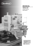
R
USER ’
S
MANUAL
SPS/D-B1202 SERIES
SPS/C-B1202 SERIES
Electronically Controlled
Button Sewing Machine
(Mechanical Part)
SUNSTAR MACHINERY CO., LTD.
1) FOR AT MOST USE WITH EASINESS,
PLEASE CERTAINLY READ THIS MANUAL
BEFORE STARTING USE.
2) KEEP THIS MANUAL IN SAFE PLACE
FOR REFERENCE WHEN THE MACHINE
BREAKS DOWN.
MME-051130
lity
a
u
tQ
Besst Pricevice
Be st Ser
Be
1. Thank you for purchasing our product. Based on the rich expertise and
experience accumulated in industrial sewing machine production, SUNSTAR
will manufacture industrial sewing machines, which deliver more diverse
functions, high performance, powerful operation, enhanced durability, and
more sophisticated design to meet a number of user’s needs.
2. Please read this user’s manual thoroughly before using the machine. Make
sure to properly use the machine to enjoy its full performance.
3. The specifications of the machine are subject to change, aimed to enhance
product performance, without prior notice.
4. This product is designed, manufactured, and sold as an industrial sewing
machine. It should not be used for other than industrial purpose.
R
SUNSTAR MACHINERY CO., LTD.
SPS / D- B 1 2 0 2 - 0 1
① Sunstar
Pattern
System
② Series
C: Motor belt-type
D: Motor direct drive-type
④ Button Type
01 : Small-Size Button
(Mechanical Type Wiper)
02: Large-Size Button
(Mechanical Type Wiper)
03 : Small & Large Size Button
(Solenoid wiper Type Wiper)
③ Button S/M Model Name
Contents
1. Machine safety regulations
6
2. Machine Specifications
9
3. Machine Structure
1) Names of each part of the machine
4. Machine Installation
1)
2)
3)
4)
5)
Machine installation conditions
Electric installation conditions
How to install the table
The assembly of peripheral parts
Change of parameters according to setting of thread wiper specifications
5. Preparations before operating the machine
1) How to supply oil
2) How to grease
3) How to attach needle
4) Checking needle and thread
5) How to pass upper thread
6) Threading the lower thread
7) How to take the bobbin case on and off
8) How to adjust the tension of the upper thread and the lower thread
9) How to wind the lower thread
10) How to operate a pedal
11) Disposing the waste oil
6. How to repair the machine
1)
2)
3)
4)
5)
6)
7)
Adjusting the height of the needle bar
Adjusting the needle and the shuttle
How to adjust the eccentricity of thread take-up crank axis
Adjusting the lower shaft gear and the rocking shaft gear
Adjusting the position of shuttle upper spring
How to adjust the ascending range of button clamp
How to adjust the button clamp holder tension
10
10
11
11
11
11
14
15
16
16
16
17
17
17
17
18
18
19
19
19
20
20
20
21
21
22
22
23
8) Adjusting the parts of thread release
9) Adjusting the parts of wiper
10) Adjusting the parts for trimming
11) Adjusting the devices for main thread adjustment
12) Adjusting the winder devices
13) Setting up the synchro position(C Series)
14) Mounting the Direct Motor and Adjusting Method(D Series)
15) Setting up the X-Y origin
16) How to adjust the feeding plate
17) Checking the setting position of button clamp
18) How to set up the button clamp adjusting plate
19) How to attach the spacer spring plate
23
24
27
29
29
30
31
31
32
32
33
33
7. Cause of Breakdown and Troubleshooting
34
8. Pattern List
36
9. Drawing of Table
37
1) SPS/D-B1202
2) SPS/C-B1202
37
38
10. Gauge List
39
11. Option List
39
1
MACHINE SAFETY REGULATIONS
Safety instruction on this manual are defined as Danger, Warning and Notice.
If you do not keep the instructoins, physical injury on the human body and machine damage might be occurred.
Danger : This indication should be observed definitely. If not, danger could be happen during the installation,
conveyance and maintenance of machines.
Warning : When you keep this indication, injury from the machine can be prevented.
Notice : When you keep this indication, error on the machine can be prevented.
1-1) Machine Transportation
Danger
1-2) Machine Installation
Notice
Only trained and experienced people should treat the machine who are fully
understand the safety rules.
For conveyance, follow the below directions.
ⓐ More than two people to a minimum should convey the machine.
ⓑ For a protection of safety accident, wipe away the oil stained on machine.
Owing to the improper environment for machine installation, physical damages on
the human body and machine can be occurred. Please follow below conditions.
ⓐ When you unwrap the packing of the machine, try from above in order.
Especially careful of nails put into edges of wood box packing.
ⓑ Since dust and humidity can cause pollution and abrasion, you should install
airconditioner with regular cleaning.
ⓒ Put in a place of no direct ray of light.
If the machine is exposed in direct ray of light for a long time, transformation
of color and shape can be happened.
ⓓ To get enough space in case of repair, make the machine 50cm apart from the
right and left and back side of wall to a minimum.
ⓔ EXPLOSION HAZARDS
Do not operate in explosive atmospheres. To avoid explosion, do not operate
this machine in an explosive atomosphere including a place where large
quantities of aerosot spray product are being used or where oxygen is being
administered unless it has been specifically certified for such operation.
ⓕ The machines where not provided with a local lighting due to the feature of
machine. Therefore the illumination of the working area must be fuifilled by
end user.
[Refer] Details for installation of machine is described in‘4. Machine Installation.’
1-3) Machine Repair
Danger
6
If you have any problems on the machine, troubleshooting should be handled by
the designated A/S engineers.
ⓐ Before cleaning and repairing machine, cut off the main power and wait for 4
minutes until the machine comes to be completely discharged.
ⓑ You should not change the specification of machine and any part of machine
without consulting with our company. Those changes can threaten the safety of
machine during the operation.
ⓒ You should exchange from the used one into SWF guaranteed devices.
ⓓ After finishing troubleshooting, cover the all covers that are uncovered during
repairing.
1-4) Machine Operation
Warning
SPS/D(C)-1202 Series are made for industrial use to perform button sewing to
fabrics or its similar materials. Please observe the following principles.
ⓐ Read the manual to understand on the operation of machine perfectly.
ⓑ Wear suitable clothes and cap for safe operation.
ⓒ During operation, don’t make you body close to operating part of machine such
as needle, hook, take-up lever or pulley.
ⓓ Do not remove a safety plate and covers during operation
ⓔ Be sure the grounding lines in connected.
ⓕ Before opening electricity box such as control box, cut off the supply of
electricity and confirm if the switch is“off”.
ⓖ When inserting thread into a needle or before inspecting after sewing, be sure
the machine is stopped.
ⓗ Do not turn on the power during pedaling.
ⓘ Do not use several motor per a electric outlet.
ⓙ Install the machine apart from noise occurrence area such as high frequency
welding machines as far as possible.
ⓚ Be careful- When the upper feed plate comes down to press. Otherwise, the
finger or hand hight be hurt at smacking.
Warning
1-5) Devices for safety
Notice
Belt will crush or amputate finger or hand, keep cover in place
before operating, turn off power before inspecting or adjusting.
ⓐ Safety label : It describes cautions during operating the machine.
ⓑ Thread take-up cover : It prevents from any contact between body and take-up lever.
ⓒ Motor Cover(D Series) : It prevents from insertion of hands, feet or clothes by Motor.
Belt Cover(C Series) : It prevents from insertion of hands, feet or clothes by V-belt Motor.
ⓓ Label for specification of power : It describes cautions for safety to protect against
electric shock during rotating the motors.
ⓔ Finger guard : It prevent from contacts between a finger and needle.
ⓕ Safety plate : It protects eyes against needle breaks.
ⓑ
ⓒ
ⓐ
ⓕ
ⓔ
ⓓ
7
1-6) Caution Mark Position
Caution mark is attached on the machine for safety.
When you operate the machine, observe the directions on the mark.
Position of Warning Mark
CAUTION
경 고
Do not operate without finger guard and
safety devices. Before threading, changing
bobbin and needle, cleaning etc. switch off
main switch.
손가락 보호대와 안전장치 없이 작동하지
마십시오.
실, 보빈, 바늘교환시나 청소전에는 반드시 주
전원의 스위치를 꺼 주십시오.
CAUTION
경 고
Hazardous voltage will cause injury.
Be sure to wait at least 360 seconds before
opening this cover after turn off main switch
and unplug a power cord.
고압 전류에 의해 감전될 수 있으므로 커버를
열 때는 전원을 내리고 전원 플러그를 뽑고 나
서 360초간 기다린 후 여십시오.
1-7) Contents of Marks
Caution
1)
CAUTION
경 고
Do not operate without finger guard
and safety devices. Before threading,
changing bobbin and needle, cleaning
etc. switch off main switch.
Warning
손가락 보호대와 안전장치 없이 작동하지 마
십시오.
실, 보빈, 바늘교환시나 청소전에는 반드시
주전원의 스위치를 꺼 주십시오.
2)
CAUTION
경 고
Hazardous voltage will cause injury.
Be sure to wait at least 360 seconds
before opening this cover after turn
off main switch and unplug a power
cord.
고압 전류에 의해 감전될 수 있으므로 커버
를 열 때는 전원을 내리고 전원 플러그를 뽑
고 나서 360초간 기다린 후 여십시오.
8
2
Name of Model
SPS/D(C)-B1202-01 SPS/D(C)-B1202-02 SPS/D(C)-B1202-03
Speed
Max. 2,500spm (Standard : 2,200spm)
Button Size
ф8~ф20mm
Wiper Specification
Needle
ф8~ф32mm
Mechanical Type Wiper
ф8~ф32mm
Solenoid Type Wiper
DP×17 #14
Hook
Semi-Rotary Standard Shuttle Hook
Button Clamp Lift
Max. 13mm
No. of Patterns
Max. 99 Patterns (Standard: 33 Patterns)
No. of Stitches
Max. 10,000 Stitches
Enlargement / Reduction
Memory
P-ROM
Proper Temperatare of
machine running
Proper Humidity of
machine running
Main Motor
20%~200%
5℃~40℃ (41℉~104℉)
20%~80%
D Series
Direct Drive AC Servo Motor
C Series
AC Servo Motor
Power
Consumption Power
1ф : 100~240V / 3ф : 200V~440V, 50/60Hz
600VA
9
3
MACHINE STRUCTURE
1) Names of each part of the machine
Arm
Mortor Cover
Thread
Stand
Safety Plate
Operation Box
Power Switch
Control Box
Pedal Switch
10
4
MACHINE INSTALLATION
1) Machine installation conditions
A. Do not use the machine where the voltage is over regular voltage ±10% to prevent accidents.
B. For safe operation of the machine, use the machine under the following conditions.
Surrounding Temperature During Operation : 5℃~40℃
Surrounding Temperature During Maintenance : -10℃~60℃
C. Humidity : Between 20~80%(Relative humidity)
2) Electric installation conditions
A. Power Voltage
·The power voltage must be between regular voltage ±10%.
·The frequency of the power should be regular frequency (50/60HZ)±1%.
B. Electromagnetic Wave Noise
Use separate power with strong magnetics or high frequency products, and do not leave the machine
near them.
C. Use low voltage when supplements or accessories are being adhered.
D. Be careful not to have water or coffee be spilled into the Controller and Motor.
E. Do not drop the Controller or Motor.
3) How to install the table
A. Fix the oil tub holder ①, oil holder ②,
control box ③, and main switch ④ on
the table.
B. In case of SPS/C-B1202 series, attach the
bed cushion rubber to the table.
②
①
③
④
Cushion Rubber
[ Fig. 2 ]
[ Fig. 1 ]
C. In case of SPS/D-B1202 series, attach the
bed cushion rubber ① and safety switch
supporting rubber ② to the table.
②
①
[ Fig. 3 ]
11
D. Add the hinge metal and hinge rubber to the
bed. Then insert the fixing bolt into the
hinge metal hole of point ① and fix the table
as shown in the picture.
Bolt
Hinge
Rubber
The machine should be carried
by more 2 people for safety
Danger
①
Hinge
[ Fig. 4 ]
E. In case of SPS/D-B1202 series, assemble the
safety switch bracket ① on the bed as in the
figure. Move the safety switch bracket up
and down to make sure that the safety
switch supporting rubber② is tightly pressed
by the safety switch③, and then fasten the
screw④.
①
②
④
③
[ Fig. 5 ]
F. Stand the machine as shown in the picture,
and then fix the machine on the table after
inserting the fixing bolts into the hinge metal
holes of point ①.
Danger
Since the machine is not perfectly
installed on the table, extreme care is
needed when you make the machine
stand up not to have any accident
occurred.
①
Bolt
①
[ Fig. 6 ]
G. Put the “V”-Belt in between the pulley and
the motor while the machine is standing as
in the picture.(C Series)
Pulley
V-Belt
Motor Cover
[ Fig. 7 ]
12
H. After connecting the “V”-Belt, if the fixing
nuts① and ② are vertically unfastened
sufficiently tension occurs in belt D due to
the weight of motor C. At this point, first
screw in fixing nut ① A, then nut ② in
fixing screw B tightly. And, finish the cable
connection between the embroidery machine
and the control box, then fix the cable
wiring under the table as shown in the
Figure. (The length of cable should be set
up considering when the machine is put
aside.) (C Series)
D
①
②
C
[ Fig. 8 ]
I. Be sure to connect the earthing conductor
(green)between the sewing machine and the
motor. And also, connect the earthing conduct
or between the control box and the motor.
(C Series)
Conductor
[ Fig. 9 ]
J. In case of D series, connect the conduct of
sewing machine and control box as in the
picture.
Conductor
[ Fig. 10 ]
13
4) The assembly of peripheral parts
A. Attach the motor cover to the back side of machine and sides by using fixing bolts
(In case of C series, attach the belt cover by using fixing screws for the rear (3EA) and the side (2EA).)
Fixing Screw
Fixing
Screw
Motor Cover
Velt Cover
Fixing Screw
C series
D series
[ Fig. 11 ]
[ Fig. 12 ]
For safety, motor cover and safety plate should be attached to the machine.
Caution
B. Install the thread stand on the table.
C. Fix the button case base① in the bottom of
flat table to the easy working position using a
screw②. And insert the button case③ into the
button case base①, then fix it with a fixed
screw④.
③
②
[ Fig. 13 ]
14
④
①
[ Fig. 14 ]
5) Change of parameters according to setting of thread wiper specifications
·Parameters are changed according to mechanical thread wiper specifications upon initialization.
·For change of parameters according to setting of thread wiper specifications, refer to the following
table :
Function No.
A14
A31
Mechanical Type
0
1
Electronic Type
1
0
Wiper Specification
·For more information, refer to“Memory Switch Function Table”.
15
5
PREPARATIONS BEFORE OPERATING THE MACHINE
1) How to supply oil
A. Check the remaining oil in the oil tank in the
arm and bed, and supply the oil sufficiently
on the arrowed parts on the Figure 16 with
a lubricator.
Caution
Be sure to supply oil when
operating the machine for the
first time and when the machine
has not been used for a long
time.
[ Fig. 16 ]
B. Open the hook cover and supply oil till the
shuttle race ring is surrounded by oil. Put
the hook cover closed after finishing.
Caution
For safety, keep the hook cover
closed during operating.
Shuttle Race Ring
Hook Cover
[ Fig. 17 ]
2) How to grease
Supply a little grease on the arrowed parts in
the Figure16. Too much grease prevents the
clamp from moving up and down, therefore an
error message
-[“Er 05”] is displayed.
[ Fig. 18 ]
16
3) How to attach needle
Loosen the needle fixing screw① in the needle
bar, place the long groove of needle② toward to
user and push it until the needle upper point
gets to the needle insert hole, then fix it with
the needle fixing screw①.
①
②
[ Fig. 19 ]
4) Checking needle and thread
Refer to the right table when selecting the
needle and thread to use according to working
conditions.
(Cotton thread or span thread is available.)
Needle
Upper Thread Lower Thread
DP×17 #14
#60
#80
#50
#60
#40
#60
#60
#60
5) How to pass upper thread
Place the thread take-up lever on the top
position, and hang the upper thread as shown in
the Figure20. About 40mm of the upper thread
should come out from the needle eye.
[ Fig. 20 ]
6) Threading the lower thread
A. Insert bobbin ① into bobbin case ② as
shown in the Figure21.
Caution
Insert the bobbin to turn clockwise
when seen from behind the bobbin
case
25mm
③
②
①
B. After setting the lower thread through the
crack of the bobbin case, insert the thread
through thread hole ③.
C. Adjust the lower thread to hang 25mm out
of thread hole ③.
[ Fig. 21 ]
17
7) How to take the bobbin case on and off
Opening the hook cover, hold the knob ① of
bobbin case and push into the shuttle until
sounding.
Caution
If you start operating the machine
when a bobbin case is not perfectly
installed, thread can be tangled of the
bobbin case would be protruded.
①
Bobbin Case
[ Fig. 22 ]
8) How to adjust the tension of the upper thread and the lower thread
A. Adjusting the Tension of the Upper Thread
When the tension adjusting nuts ③ and ④,
of thread tension adjusting unit ① and subtension adjusting unit ②, are turned
clockwise the upper thread is tightened. And
loosens when turned the other way around.
④
②
①
③
[ Fig. 23 ]
B. Adjusting the Tension of the Lower Thread
The lower thread becomes tight when tension
adjusting screw ① is turned clockwise, as
shown in the picture. When the screw is
turned the other way the lower thread is
loosened.
①
[ Fig. 24 ]
18
9) How to wind the lower thread
A. Press SELECT on operation box and select
.
B. Insert the bobbin into the thread winder drive shaft ② on thread winder base ①, attched to the
upper cap.
C. Adhere the bobbin winder lever ③ closely to a bobbin, then let the machine run by pressing pedal.
D. After the bobbin winder lever takes off from a bobbin, cut the thread of bobbin by using bobbin
winder knife ④.
[ Fig. 25 ]
10) How to operate a pedal
A. Install a pedal switch in the proper position
for the convenience of work.
B. If you step on pedal one step, the button
clamp descends, and if take off your feet
from the pedal, it ascends.
C. If you step on two step the pedal switch
after stepping on it one step, the sewing
starts, and after finishing it,the button clamp
ascends.
↓
→
[ Fig. 26 ]
11) Disposing the waste oil
When the oil receiving oiler at the bottom of
the table is full, take it off to empty.
Caution
Oiler
Spread out some fabrics or papers
on the floor when you attach or
remove the oil receiving container.
[ Fig. 27 ]
19
6
HOW TO REPAIR THE MACHINE
The machine is set to be the best condition at the factory. Do not make any discrete
adjustments on the machine and replace genuine parts approved by the company only.
Caution
1) Adjusting the height of the needle bar
①
Loosen the needle bar clamp screw① at its
lowest point, adjust the upper punched mark of
the needle bar to conform to the bottom of the
needle bar bushing as shown in the Figure28,
then tighten the needle bar clamp screw①.
Upper
punched
mark
[ Fig. 28 ]
2) Adjusting the needle and the shuttle
A. As shown in the Figure29, go up the needle
bar from its lowest point, and conform the
lower-left punched mark of the needle bar to
the lower bushing of the needle bar.
Needle Bar
Lower Bushing
Lower
punched mark
[ Fig. 29 ]
B. After unfastening the shuttle drive screw①, open the inner hook pressure bar ② left to right and remove
the shuttle Race ring ③ from the (large) shuttle ④.
C. Make the shuttle hook point
accord with the center of the needle. And make the needle and the front
face of the shuttle drive
connect each other to prevent the needle from curving. Then, tighten the drive
screw ① firmly.
D. After unfastening the (large) shuttle screw⑤, turn the large hook adjustment shaft ⑥ to the left to right
and adjust the (large) shuttle ④ so that the needle and the shuttle hook point
is 0.05~0.1mm apart
from each other.
E. After adjusting the (large) shuttle ④ in place, adjust the rotary direction of the (large) shuttle ④ so the
needle and the (large) shuttle ④ is 7.5mm apart from each other.
Then, tighten the (large) shuttle screw ①.
For safety, make sure all the screws are tightened firmly after adjusting the (large) shuttle.
Caution
0mm
7.5mm
→ →
0.05~0.1mm
②
②
→
⑤⑥
④
③
20
①
3) How to adjust the eccentricity of thread take-up crank axis
A. Disassemble the face plate from an
embroidery machine, then remove a clamp
screw in the thread take-up crank axis.
③
B. Loosen a fixed screw of the thread take-up
crank axis in the left of arm.
C. Rotate the thread take-up crankshaft③ to
place its eccentric part to the upper
direction. And adjust the driver’s groove
horizontally.
②
①
D. Tighten the fixed screw of the thread takeup crank axis, then reassemble the clamp
screw of the thread take-up crank axis.
[ Fig. 31 ]
4) Adjusting the lower shaft gear and the rocking shaft gear
A. Unfasten screws ①, ②and ③.
B. While having the upper shaft turning, move the rocking shaft gear in the direction of the arrow to
the position where it will move easily without load.
The machine may not operate when the rocking shaft gear in not in the right position.
Caution
C. Have the oscillator shaft collar(right) stick to the bed surface , and then tighten the collar screw.
D. Turn the oscillator shaft collar(right), still sticking to the bed surface , in the direction of the
arrow and make adjustments so the end of the shuttle drive will rotate smoothly with the backlash
of under 0.1mm.
If there is too much backlash the machine may make more noise than usual during
operation. And if there is not enough backlash, the machine may not operate.
Caution
E. Tighten screw ① and ③ back on firmly.
③
Oscillator Shaft
Collar(R)
below 0.1mm
→←
①
②
[ Fig. 32 ]
21
5) Adjusting the position of shuttle upper spring
After removing the lower feed plate and the needle plate from the machine, unfasten the screw of the
shuttle upper spring. Then, adjust the shuttle upper spring so that the backside of the needle and comes
to point
in the vertical direction, and the center of the needle will come to the middle of interval
horizontally. After the adjustment is done, tighten the screw back on firmly.
Caution
The thread may be disconnected or the thread strand may be unfastened if there are scratches or if
the surface is rough around the Shuttle upper spring. Always check the surface of the spring before
operating the machine.
①
①
①
[ Fig. 33 ]
6) How to adjust the ascending range of button clamp
To adjust the ascending range of button clamp, take out its tension adjusting screw①, loosen the fixed
screw②, adjust the holder bar of button clamp up and down to place it to the suitable position, then
tighten the fixed screw②. And attach the tension adjusting screw① on the original position again.
③
②
①
13mm
[ Fig. 34 ]
※ The maximum rising height of button clamp is 13mm from the presser foot.
(The rising height of button clamp upon delivery is adjusted to 10~11mm.)
22
[ Fig. 30 ]
7) How to adjust the button clamp holder tension
Adjust it smoothly to the extent that sewing
cloth does not move during sewing, and fix it
with the tension adjusting nuts - ① and ②.
②①
[ Fig. 35 ]
8) Adjusting the parts of thread release
A. How to Set the Thread release Notch
Place the notch so that the right side of the
slot of the thread release notch ① touches
circumference of the notch screw ②, and then
fix with a screw.
Caution
②
①
The remaining amount of thread
may not be enough or not be
regular and the thread may be
unfastened from the needle if the
notch is not set in the right position.
Thread
Trimmer
Cam
[ Fig. 36 ]
B. How to Set the Thread Release Stopper
ⓐ Remove the thread release return spring.
ⓑ After unfastening the thread release stopper screw, adjust the trimming drive link and the thread
release lever pin 0.3mm apart from each other. Then, attach the arm to the thread delay stopper
completely. When the thread release stopper is pushed to the right, the space between the
trimming drive link and the thread release lever pin is reduced. And it is enlarged when the stopper
is pushed to the left.
ⓒ Hang on the thread release return spring.
For safety, use a tool when removing or attaching the thread release return spring.
Caution
Thread Release
Lever Pin
Thread
Trimming
Driving Link
Return Spring
Screw
→→
0.3mm
Widen
Narrow
Thread Release
Stopper
[ Fig. 37 ]
23
C. How to adjust the opening capacity of the thread guide disk
ⓐ Unfasten the thread release adjusting plate screw.
ⓑ Open the thread guide disk by operating the trimming devices.
ⓒ Adjust the opening capacity to 0.6~0.8mm for normal material and 0.8~1mm for heavy material.
To increase the opening capacity, widen the angle between the thread release plate and narrow
the angle to reduce the opening capacity.
ⓓ Tighten the screw after the adjustment.
If the disk is not opened appropriately, the amount of remaining thread may be not enough or
not regular, and the disk may not be closed completely.
Caution
Widen
→ → Floating Amount
Narrow
Upper Shaft
To Thread Tension
Adjusting Ass’y
Screw
Thread Tension Adjusting Plate
To Tension Release Link
[ Fig. 38 ]
9) Adjusting the parts of wiper
A. Adjusting method of kinematic type wiper(SPS/D(C)-B1202-01, 02)
ⓐ Unfasten the wiper base plate bolt ②.
ⓑ When the thread wiper and the needle center are in a straight line, adjust the thread wiper base③
up and down that the interval between the needle① and the thread wiper can be 2.5mm, then
tighten the clamp②.
ⓒ Unfasten the wiper rod bolt ④.
ⓓ Adjust the thread connecting rod⑤ up and down that the thread wiper under sewing standby can
have the interval of 15~17mm from the needle center, then tighten the thread wiper rod clamp④.
ⓔ The thread wiper spring attached on the thread wiper base has the function to hold upper thread
after thread trimming, and its proper tension is about 20~30g. (A little stronger than the tension of
lower thread in the bobbin case)
If the wiper is not placed in the right position, the wiper may collide with the presser foot
or needle during the operation, and the wiper may not move properly.
Caution
②
Needle ①
③
2.5mm
④
15~17mm
[ Fig. 39 ]
24
⑤
⑥
[ Fig. 40 ]
B. Installation and adjusting method of solenoid wiper (SPS/D(C)-B1202-03)
ⓐ Fix the wiper base plate with screw as
shown in the figure41.
[ Fig. 41 ]
ⓑ Fix the wiper base at the opposite
direction with two screws as shown in the
figure42.
[ Fig. 42 ]
ⓒ Connect the connector located at solenoid
with the connector came out from arm.
[ Fig. 43 ]
25
ⓓ Loosen the base clamp②, adjust
the thread base③ up and down
that the interval between the
thread wiper and the needle
center can be 2.5mm when the
thread wiper and the needle center
are in a straight line, then tighten
the clamp②
②
③
[ Fig. 44 ]
2.5mm
①
[ Fig. 45 ]
ⓔ Loosen the thread crank clamp④,
adjust the thread wiper crank⑤
that the thread wiper under sewing
standby can have the interval of
15~17mm from the needle center,
then tighten the wiper crank
clamp④.
④
15~17
⑤
[ Fig. 46 ]
[ Fig. 47 ]
ⓕ Finally, after arranging the
connector as shown in the
figure48, attach the wiper cover
⑥ by using wiper cover joint
screw⑦.
[ Fig. 48 ]
ⓖ The thread wiper spring⑧ attached on the thread wiper base has the function to hold upper thread after
thread trimming, and its proper tension is about 20~30g. (A little stronger than the tension of lower thread
in the bobbin case)If the tension of the thread wiper spring is strong, the thread may come upward the
button.
To use the thread wiper solenoid, the sewing related function number, A-18 should be set up to
“100”. In addition to, check if A-14 is set up to“1”and A-31 to“0”.
Caution
26
10) Adjusting the parts for trimming
A. Setting the position of the trimming Cam
Set the upper shaft collar and the trimming cam 1.7mm apart from each other and place the
trimming cam where the trimming cam carving line accords with the upper shaft carving point.
Then, tighten screw ①.
Caution
If the trimming cam is not placed in the right position, the trimming operation may not
be made correctly or the machine may be lock.
Thread Trimmer Cam
1.7mm
Carving
Line
→ →
Upper Shaft
Carving Point
Upper Shaft
Upper
Shaft
Collar
①
[ Fig. 49 ]
B. How to adjust the link stopper
ⓐ With the needle bar in its lowest position, check if there is enough clearance between thetrimming
cam roller and both ends of the trimming cam when the trimming drive link is pushed in the
direction of the arrow( ) within the trimming cam moving part.
Caution
If there is not enough clearance between the trimming cam roller and both ends of the
trimming cam, trimming may not be operated correctly or the machine may be lock when
beginning to sew or trimming.
ⓑ Make the end of the link stopper screw touch part
of the trimming link stick when the
trimming cam roller is inserted into the trimming cam moving part. Then, tighten the nut.
Thread
Trimmer
Cam Roller
→→
→→
Caution
If the position is not set appropriately, the return to the previous point after trimming may be
delayed and the first stitch may not be tight enough.
Thread Trimming Driving Link
Clearance
Clearance
Thread Trimmer Cam
Link Stopper Screw
Link Stopper Screw
Thread Trimmer
Connecting Rod
Thread Trimmer
Connecting Rod
Nut
[ Fig. 50 ]
27
C. Setting the trimming shaft in place
ⓐ Unfasten the trimming drive link screw and the trimming shaft collar screw.
ⓑ Make the trimming shaft step accord with part
of the arm.
ⓒ Tighten the screws.
Caution
If the position is not adjusted appropriately, trimming may not be operated correctly or
the machine may be lock.
Thread Trimmer Cam
Thread Trimmer Shaft
Screw
Thread Trimming Collar for
Driving Link
Thread Trimmer Shaft
Caution
0.3mm
Thread
Trimmer
Driving
Link
If the link stopper is not set in the
right position, trimming may not be
operated correctly and the machine
may be lock.
Screw
→
→
D. Setting the Link Stopper in Place
ⓐ Unfasten the trimming drive link stopper
screw while trimming is not operated and
have the trimming drive link and the
trimming drive link stopper notch 0.3mm
apart from each other.
ⓑ Tighten the screw.
→→
[ Fig. 51 ]
0.3mm
Thread Trimmer Driving
Link Stopper
[ Fig. 52 ]
E. Setting the Thread Trimming Solenoid in Place
ⓐ After unfastening the thread trimming solenoid bracket screw, have the trimming shaft and the thread
trimming solenoid rotary link 0.5mm apart from each other and tighten the screw back on.
ⓑ Unfasten the thread trimming solenoid rotary link screw and drive the thread trimming solenoid rotary
link manually to move the trimming shaft collar 6.8mm in the direction of the arrow. Then, tighten the
screw back on.
ⓒ Check if the trimming shaft collar returns to its place when the thread trimming solenoid rotary
link returns.
Caution
If the position is not set right, the trimming return or the thread delay may be delayed to bring poor
sewing quality.
Screw
Thread Trimmer Solenoid Bracket
Solenoid
→→
Screw
0.5mm
Thread Trimming Rotation Link
Thread
Trimming
Rotation Link
→ →
6.8mm
Thread Trimmer Shaft
[ Fig. 53 ]
28
F. Adjusting the Moving Knife and the Fixed Knife
ⓐ When the needle bar stops at the upper position, use the trimming lever adjustment screw to
adjust space A between the thread separation point of the moving knife and the needle plate hole
as indicated in the table.(4.5mm)
ⓑ Use the fixed knife screw to adjust space B between the fixed knife and the needle plate cover as
indicated in the table. (0.5mm)
ⓒ after the adjustment, check the position of the mes by manual trimming operation.
Caution
Trimming may not be operated or there may not be enough remaining thread if the knife is not set
inappropriately
Fixed knife
B
→
→
Needle
Plate Cover
A
B
4.5mm
0.5mm
→
→
A
Moving Knife
[ Fig. 54 ]
11) Adjusting the devices for main thread adjustment
A. When the tension control nut ① of the thread
control device is turned clockwise, the upper
thread is tightened and becomes loose as the
nut is turned counterclockwise. Adjust the
tension according to the sewing conditions such
as material, thread, number of stitches etc.
B. To tighten the take-up lever spring, use a
driver to turn the groove ② on the edge face
of the thread tension control device shaft
clockwise. And to make the spring relax, turn
it counerclockwise.
(Standard operating quantity is 6∼8mm,
and tension is about 30g∼50g.)
Thread
Take-up
Spring
①
②
[ Fig. 55 ]
12) Adjusting the winder devices
A. To adjust the winding capacity of the bobbin,
use the beginning position of the winding
control plate, and after unfastening the screw,
turn the plate in direction A for large winding
capacity and turn in direction B for small
winding capacity.
B. Place the winding drive wheel 4mm away
from the upper shaft bushing(F) and tighten
the screw.
Upper Shaft
Bobbin
Bobbin Winder
Driving Wheel
4mm
A
Upper Shaft
Bushing(F)
B
Bobbin Winder
Adjusting Plate
[ Fig. 56 ]
[ Fig. 57 ]
29
13) Setting up the synchro position(C Series)
A. Installing the synchronizer
ⓐ Fix the synchoronizer on the back side of
arm.
ⓑ Adjust the gap between pulley and synchronizer
to be 2.5mm, then fasten the fixing screw for
pulley.
Pulley
2.5mm
Upper
Shaft
Pulley
Screw
Magnetic
Holder
Upper Shaft
Bushing(R)
Sychronizer
[ Fig. 58 ]
B. Adjusting the position of position detector
ⓐ Adjust the position of take-up lever to be same as Fig. 61 by turning the pulley. At this time, the
white carving sign
of pulley should be straight line with the carving sign
of arm.
ⓑ Adjust the clamp screw① in the pulley’s punched point, and tighten the clamp screw① where the
pulley’s punched pointⓐ conforms to its inscribed pointⓑ.
ⓒ Unfasten the screw ② on the N.D carving sign and move to the right and left, then let it suspen
on the place where the needle bar just start ascending from the bottom.
About 3mm
Direct
ion of
Rotati
on
[ Fig. 59 ]
30
②
[ Fig. 60 ]
Direction of
Rotation
①
[ Fig. 61 ]
14) Mounting the Direct Motor and Adjsuting Method(D Series)
A. When you mount the coupling on the servo-motor, fit the screw No.1 of coupling to the flat surface of the
servo motor shaft and make the clearance between the coupling and servo motor 0.7mm.
B. When you mount the coupling on the upper shaft, fit the screw No.1 of coupling to the flat surface of the
upper shaft and make the clearance between the coupling and upper shaft bushing(R) 2mm.
C. After mounting both couplings, check the positions of each screws to the aligned.
※ If the positions of each screws are not aligned, the needle does not stop normal position.
Screw NO.1
Servo Motor
O-ring
Upper Shaft
Flat
Surface
Upper Shaft
Rear
Bushing
ARM
2 Coupling
0.7
[ Fig. 62 ]
15) Setting up the X-Y Origin
A. How to set up X-axis Origin
ⓐ Separate a bed cover (left).
ⓑ Move the button inserted into the button clamp to the center of X-axis.
ⓒ As seen in the figure, unfasten the bolts of X-sensor plate and let the end of X-sensor
plate locate on the center of sensor, then fasten the bolts with screw-driver.
Screw
X-sensor plate
Sensor
[ Fig. 63 ]
31
B. How to set up Y-axis Origin
ⓐ Separate a bed cover ( right ).
ⓑ Move the center of work clamp foot to be placed on the center of Y-axis.
ⓒ As seen in the figure, unfasten the bolts of Y-sensor plate and let the end of X-sensor
plate locate on the center of sensor, then fasten the bolts with screw-driver.
Sensor
Screw
Y-sensor plate
[ Fig. 64 ]
16) How to adjust the feeding plate
A. Select Pattern No.“0”at the operation box.
B. Press [Ready] key to ascend the button
clamp that the machine can return to the
origin.
C. Adjust the feeding plate① that its center can
place to the center of presser bar cover②.
②
①
[ Fig. 65 ]
17) Checking the setting position of button clamp
A. Select Pattern No.“0”at the operation box.
B. Press [Ready] key to ascend the button clamp
that the machine can return to the origin.
C. Insert the button into the button clamp①.
D. Press the button clam of Step 1 to descend
its holder. At this time, turn the pulley for the
error message “
[ Er 03”] to display on the LCD.
E. Remove your foot from the pedal, and turn
the pulley to check if the needle point
conforms to the button’s center.
F. If the needle point does not insert into the
button’s center, loosen the fixed screw② of the
button clamp bracket, and fix it that the needle
point can be inserted into the button’s center.
G. After adjusting, check the pattern form that the
needle is exactly inserted into the button hole.
32
②
①
needle point
conform
Button
[ Fig. 66 ]
18) How to set up the button clamp adjusting plate
A. Insert the button into its clamp while the
machine stops, and check that it is exactly
inserted.
B. Loosen the button clamp adjusting screw①,
and adjust that the space between the
button clamp adjusting plate② and its
adjusting screw① can be 0.5~1mm.
0.5~1.0mm
①
②
③
[ Fig. 67 ]
19) How to attach the spacer spring plate
②
③
④
①
3.5~4mm
A. Place the spacer spring to the button’s
center, adjust it to be projected to
3.5~4mm from the button’s center to the
spring’s edge, and fix the spacer spring plate
③ to the button clamp bracket①.
B. To adjust the height of spacer spring, loosen
the screw④, place the spring to the suitable
position, and fix the screw④.
[ Fig. 68 ]
33
7
CAUSE OF BREAKDOWN AND TROUBLESHOOTING
No.
Condition of Breakdown
Cause of Breakdown
Troubleshooting
Loosing of belt tension and damage
Adjust the belt tension or exchange it
on belt
1
2
3
Error on operation or
drive of machine
Fuse shortage for main power or
circuit
Check the fuse shortage of main shaft
drive motor in a controller box or
exchange it
Deviation from Y and Y limit of
feed bracket
Move the feed bracket to normal place
(inside limit switch)
Slackness of main drive belt
Adjust the belt tension
Bad position of
stopping position
Due to improper synchro position
Adjust setting position of synchro
Exchange the needle
Needle bent
Damage on needle(Bending of
needle, cracks on needle hole or
groove, and abrasion or
transformation of needle tip)
Wrong installation of needle
Install the needle properly
Contact of needle with shuttle
Adjust the distance properly between a needle and shuttle
Wrong insertion of thread
Insert the thread properly
Wrong installation of needle (Height
Reinstall the needle.
of needle or direction of needle)
4
Thread is cut
Damage on needle (Bending of
needle, cracks on needle hole or
groove, and abrasion or
transformation of needle tip)
Exchange the needle.
Excessive tension of upper thread and under thread Adjust the tension
5
Stitch skipping
Excessive tension and stroke of
take-up lever spring
Adjust the tension and stroke of takeup lever spring
Crack on the controlling hole of
shuttle surface spring
Exchange the shuttle surface spring
Use of bending needle
Exchange the needle.
Use of improper sized needle compared with using thread
Exchange the needle.
Wrong installation of needle
Reinstall the needle.
Improper timing for needle and shuttle
Readjust the timing for needle and shuttle
Improper gap between groove and shuttle point Readjust the timing for needle and shuttle
Excessive tension of take-up lever
spring and stroke
34
Adjust the tension of take-up lever
spring and stroke
No.
Condition of Breakdown
Cause of Breakdown
Weak tension of upper thread
6
Errorin thread tightening Weak tension of lower thread
Improper timing for needle and
shuttle
Laxity of exchanging tension between
movable mes and fixed mes
7
Error in trimming
Troubleshooting
Readjust the tension of upper thread.
Readjust the tension of lower thread.
Readjust the timing for needle and shuttle
Readjust the tension of fixed mes.
Abrasion and crack on blade of movable mes
and fixed mes
Exchange the movable mes and fixed mes.
Wrong position of trimming cam.
Readjust the position of trimming cam
35
8
PATTERN LIST
Pattern
Pattern
No.
Range of Sewing
X (mm)
Y (mm)
No of
Threads
Pattern
Pattern
No.
No of
Threads
Range of Sewing
X (mm)
Y (mm)
1
6-6
3.4
3.4
18
6
3.4
0
2
8-8
3.4
3.4
19
8
3.4
0
3
10-10
3.4
3.4
20
10
3.4
0
4
12-12
3.4
3.4
21
12
3.4
0
6-6
3.4
3.4
22
16
3.4
0
8-8
3.4
3.4
23
6
0
3.4
10-10
3.4
3.4
24
10
0
3.4
12-12
3.4
3.4
25
12
0
3.4
9
6-6
3.4
3.4
26
6-6
3.4
3.4
10
8-8
3.4
3.4
27
10-10
3.4
3.4
11
10-10
3.4
3.4
28
6-6
3.4
3.4
12
6-6
3.4
3.4
*
29*
10-10
3.4
3.4
13
8-8
3.4
3.4
30
5-5-5
2.9
2.5
14
10-10
3.4
3.4
31
8-8-8
2.9
2.5
*
16*
17*
6-6
3.4
3.4
32
5-5-5
2.9
2.5
8-8
3.4
3.4
33
8-8-8
2.9
2.5
10-10
3.4
3.4
*
6*
7
*
8*
5
15
※ The magnifying and reduction range (X and Y) of standard sewing shown above is 100%
66 patterns including 33 patterns can be additionally provided.
※ In case of the pattern of“*”mark of Sewing Pattern No., a thread is trimmed after finish of first sewing to
remove a line through sewing patterns. In case of SPS/C-B1202-01 and 02, press the pedal once more after finish
of first sewing, or continuously press and release the pedal until second sewing begins.
In case of SPS/C-B1202-03, just one time pressing of the pedal will do.
A. If the central distance between use buttonholes does not conform for the standard sewing range of Sewing
Pattern No., magnify or reduce the sewing range to adjust it.
B. After the Sewing Pattern Number and the sewing range (X, Y) are changed, don’t forget to check if the
needlepoint conforms to the buttonhole with regard to [Checking Pattern Shape].
C. Rate of magnifying and reduction according to the sewing range
Sewing Area
2.4
X,Y(mm)
Expansion &
Reduction (%) 71
36
2.6
2.8
3.0
3.2
3.4
3.6
4.0
4.3
4.5
4.7
5.2
5.6
6.0
6.2
6.4
76
82
88
94
100
106
118
126
132
138
153
165
176
182
188
37
1) SPS/D-B1202
DRAWING OF TABLE
9
38
2) SPS/C-B1202
10
GAUGE LIST
MODEL
SPS/D(C)-B1202
Button Size
Small Button
Midium Button
Large Button
External diameter of Button
(mm)
ф8~ф15
ф10~ф20
ф15~ф32
(Y)
0~3.5
0~4.5
0~6.5
(X)
0~3.5
0~4.5
0~6.5
Thickness
1.3 (2.2)
2 (2.7)
2.7 (3.2)
Stitch Size
(mm)
Punched mark
Button Clamp
Code
Ass’
y
No.
Right
Left
Punched mark
Punched mark
23-033A-120B
A
23-056A-120B
B
23-063A-120B
C
(23-050A-120B)
1
(23-063A-120B)
2
(23-076A-120B)
3
23-026A-120B
A
23-053A-120B
B
23-066A-120B
C
(23-047A-120B)
1
(23-060A-120B)
2
(23-073A-120B)
3
Needle Plate Cover
10-042A-120B
10-043A-120B
10-044A-120B
Feed Plate
23-043A-120B
23-058A-120B
23-071A-120B
※ (
): Special Option
11
NAME
Code No.
Button Spacer Ass’
y
23-182A-120B
Feed Guide Bracket
20-149A-120B
Feed Plate
Small Button
23-094A-120B
Midium Button
23-095A-120B
Large Button
23-096A-120B
39