1
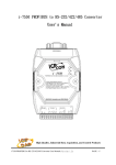
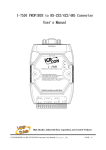
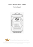
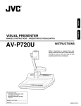
i-7550 PROFIBUS to RSRS-232/422/485 Converter
User's Manual
High Quality, Industrial Data Acquisition, and Control Products
i-7550 PROFIBUS to RS-232/422/485 Converter User's Manual (Version 1.01)
PAGE:1
Warranty
All products manufactured by ICP DAS are under warranty regarding
defective materials for a period of one year from the date of delivery to the
original purchaser.
Warning
ICP DAS assumes no liability for damages resulting from the use of
this product. ICP DAS reserves the right to change this manual at any time
without notice. The information furnished by ICP DAS is believed to be
accurate and reliable. However, no responsibility is assumed by ICP DAS
for its use, or for any infringements of patents or other right of third parties
resulting from its use.
Copyright
Copyright by ICP DAS. All rights are reserved.
Trademark
The names used for identification only may be registered trademarks
of their respective companies.
List of Revision
Author
Raiden
Version
1.01
Revision
Release
i-7550 PROFIBUS to RS-232/422/485 Converter User's Manual (Version 1.01)
PAGE:2
Table of Contents
1. Introduction ......................................................................................... 4
1.1
Features ....................................................................................... 5
1.2
Specification................................................................................ 5
2. Hardware ............................................................................................. 7
2.1
Block Diagram of i-7550 ............................................................ 7
2.2
Pin Assignment ........................................................................... 7
2.3
Hardware connection .................................................................. 9
2.4
PROFIBUS bus connector and cable selection ........................ 14
2.5
PROFIBUS bus connection ...................................................... 15
2.6
Address setting .......................................................................... 16
2.7
LED status indicator.................................................................. 18
3. Communication ................................................................................. 19
3.1
Field of application ................................................................... 19
3.2
GSD file..................................................................................... 20
3.3
The Configuration of the parameters of the i-7550 .................. 23
3.4
The Configuration of the device modules ................................ 24
3.5
I/O data exchange...................................................................... 25
3.6
Establish connection with i-7550.............................................. 28
3.7
The data exchange demo........................................................... 29
4. Troubleshooting................................................................................. 38
5. Dimensions........................................................................................
39
Dimensions
i-7550 PROFIBUS to RS-232/422/485 Converter User's Manual (Version 1.01)
PAGE:3
1.
Introduction
PROFIBUS is the fieldbus communication system with the wide
range of applications, particularly in the fields of factory and process
automation. In order to use the traditional serial devices (RS232/422/485
devices) in the PROFIBUS network, ICP DAS provides the i-7550 to
achieve this goal.
The i-7550 integrates devices with serial RS-232, RS-485 or RS-422
interface into Profibus DP. The i-7550 works as a Profibus DP slave
module and enables the utilisation of normal DP process data for
transparent communication over a serial interface. The i-7550 enables the
integration of systems such as serial I/O devices, electronic scales,
operator terminals, barcode readers and other automation devices which
use a RS-232/RS-485/RS-422 interface into PROFIBUS DP applications.
Figure 1 shows the application architecture for i-7550 modules.
Figure 1
Application architecture of the i-7550 modules
i-7550 PROFIBUS to RS-232/422/485 Converter User's Manual (Version 1.01)
PAGE:4
The main features and specification of i-7550 are described as below:
1.1
●
●
●
●
●
●
●
●
●
●
●
●
●
1.2
Features
16-Bit Microprocessor inside with 80MHz
Siemens SPC3 PROFIBUS controller
Supports PROFIBUS DP-V0 slave
PROFIBUS transmission rate detect automatically
Max transmission speed up to 12M bps for PROFIBUS and 115.2K
bps for COM Port
COM Port driver has 1K bytes QUEUE input buffer & 512 bytes
QUEUE output buffer
Max length of in/output data is 128 Bytes
Built-in self-tuner ASIC controller on RS-422/485 port
2500Vrms High Speed iCoupler Isolation Protection for PROFIBUS
network
3000VDC Isolation Protection on the PROFIBUS side
Provide LED indicators
Built-in Watchdog
Mountable on DIN Rail
Specification
COM Port specs:
● Serial port - RS-232/RS-422/RS-485
● Serial port interface: 14-pin screw terminal block
● Baud Rate:1200/2400/4800/9600/19200/38400/57600/115200 bps
● Data Format: 7/8 data bits, None/Odd/Even parity bit, 1 stop bit
PROFIBUS specs:
● PROFIBUS interface connector: D-sub 9-pin female
● Baud Rate: 9.6K/19.2K/45.45K/93.75K/187.5K/500K/1.5M/3M/6M/
12Mbps
● Address Setting: 0~126 (set by DIP switch or EEPROM)
i-7550 PROFIBUS to RS-232/422/485 Converter User's Manual (Version 1.01)
PAGE:5
Power requirement:
● Unregulated +10V ~ +30V DC
● Power reverse protection, Over-Voltage brown-out protection
● Power consumption 2.5W
Module specs:
● Dimensions: 119mm X 72mm X 33mm
● Operating temperature: -25 ~ 75 ºC
● Storage temperature: -30 ~ 85 ºC
● Humidity:5 ~ 95%, non-condensing
● LED Status Indicators:
PWR LED
ERR LED
RUN LED
Show the power state/COM Port
data transmit and receive
state
Show error state
Show communication state of
PROFIBUS
i-7550 PROFIBUS to RS-232/422/485 Converter User's Manual (Version 1.01)
PAGE:6
2.
2.1
Hardware
Block Diagram of i-7550
RS-485
DRIVE
Figure 2: Block diagram of i-7550
2.2
Pin Assignment
Figure 3: Pin assignment of i-7550
i-7550 PROFIBUS to RS-232/422/485 Converter User's Manual (Version 1.01)
PAGE:7
Table 1:
14-pin screw terminal block
Pin
Name
Description
1
D+
Data+ of RS-485
2
D-
Data- of RS-485
3
-
4
TX+
Transmit Data+ of RS-422
5
TX-
Transmit Data- of RS-422
6
RX+
Receive Data+ of RS-422
7
RX-
Receive Data- of RS-422
8
-
9
RX
Receive Data of RS-232
10
TX
Transmit Data of RS-232
11
GND
12
-
13
+VS
V+ of Power Supply(+10 to +30VDC)
14
GND
GND of Power Supply
N/A
N/A
GND of RS-232
N/A
Table 2: PROFIBUS DB9 Female Connector
Pin
Name
Description
1
-
N/A
2
-
N/A
3
B
Non-inverting Bus Line
4
ISODE
5
GND
6
VP
7
-
N/A
8
A
Inverting Bus Line
9
-
N/A
Isolated DE output for use in PROFIBUS
applications where the state of the isolated drive
enable node needs to be monitored.
Power supply ground for the first node and the last
node
+5V Power Supply for the first node and the last
node
i-7550 PROFIBUS to RS-232/422/485 Converter User's Manual (Version 1.01)
PAGE:8
2.3
Hardware connection
i-7550 module supports PROFIBUS to Serial Port communication.
It is recommended to use only one serial port (RS232, RS485 or RS422) of
i-7550 at the same time for the serial data identification clearly. The 3
kinds of serial wire connections in i-7550 are described in section 2.3.1,
2.3.2 and 2.3.3. The positions of the pull high/low resistors in i-7550
module are shown in figure 4.
Figure 4 The positions of pull high/low resistors in i-7550 module
2.3.1
RS-232 connection
The RS-232 port in i-7550 is 3-wires. The RS232 wire connection
between the i-7550 and RS-232 device is shown in figure 5.
i-7550 PROFIBUS to RS-232/422/485 Converter User's Manual (Version 1.01)
PAGE:9
i-7550
RS-232 terminal
RS-232 device
Figure 5 RS-232 connection
2.3.2
RS-422 connection
The RS-422 wire connection between the i-7550 and RS-422 device is
shown in figure 6.The i-7550 module provides jumpers for user to set
the pull high/low resistor or not. The setting of pull high/low resistor is
shown in table 3 and figure 7,8.
i-7550
RS-422 terminal
RS-422 device
Figure 6 RS-422 connection
i-7550 PROFIBUS to RS-232/422/485 Converter User's Manual (Version 1.01)
PAGE:10
Figure 7
The configuration of pull high/low resistor
Table 3
The setting of pull high/low resistor
Pull high/low resistor
condition
enable
(default)
When i-7550 is master device in RS422 bus or the amount of connection
equipment is less than 10 in RS-422
bus
disable
When i-7550 is slave device in RS422 bus or the amount of connection
equipment is more than 10 in RS-422
bus
i-7550 PROFIBUS to RS-232/422/485 Converter User's Manual (Version 1.01)
PAGE:11
RS-422 Pull high/low
resistor enable
Figure 8
2.3.3
RS-422 Pull high/low
resistor disable
jumpers position
RS-485 connection
The RS-485 wire connection between the i-7550 and RS-485 device is
shown in figure 9. The i-7550 module provides jumpers for user to set
the pull high/low resistors or not. The setting of pull high/low resistors
is shown in table 4 and figure 10,11.
i-7550
RS-485 terminal
RS-485 device
RS-485 device
Figure 9 RS-485 connection
i-7550 PROFIBUS to RS-232/422/485 Converter User's Manual (Version 1.01)
PAGE:12
Figure 10
The configuration of pull high/low resistor
Table 4
The setting of pull high/low resistor
Pull high/low resistor
condition
When i-7550 is master device in RSenable
485 bus or the amount of connection
(default)
equipment is less than 10 in RS-485
bus
When i-7550 is slave device in RS485 bus or the amount of connection
disable
equipment is more than 10 in RS-485
bus
RS-485 Pull high/low
resistor enable
Figure 11
RS-485 Pull high/low
resistor disable
jumpers position
i-7550 PROFIBUS to RS-232/422/485 Converter User's Manual (Version 1.01)
PAGE:13
2.3.4
PROFIBUS connection
The connector of PROFIBUS interface in i-7550 is DB9 female. It
is the standard pin assignment of the PROFIBUS device. All
PROFIBUS device can be connected by the PROFIBUS cable, as
shown in figure 12.
Figure 12 PROFIBUS connection
2.4
PROFIBUS bus connector and cable selection
It is recommended to use the standard PROFIBUS cable and
connector (DB9 male) in the i-7550. When Cable have follow
properties, it has different transmission distance with respect to
different transmission rate, as shown in table 5.
1.
2.
3.
4.
5.
Impedance :135~165Ω。
Capacity : lower than 30 pF/m
Loop resistance : lower than 110Ω/Km
Wire diameter : larger than 0.65mm
Core cross-section : large than 0.34mm2
i-7550 PROFIBUS to RS-232/422/485 Converter User's Manual (Version 1.01)
PAGE:14
Table 5 Transmission distance compare with transmission rate
Transmission Rate(Kbps) Transmission Distance per Segment (meter)
9.6; 19.2; 45.45; 93.75
1200
187.5
1000
500
400
1500
200
3000; 6000; 12000
100
2.5
PROFIBUS bus connection
In order to minimize the reflection effect of signal transmission,
PROFIBUS device has to fit with an active terminal resistor at the first
node and last node, as shown in figure 13. In standard PROFIBUS
connector it is built in terminal resistor, the users can connected/disconnected terminal resistor by the connector, as shown in figure 14.
Figure 13 PROFIBUS connection
i-7550 PROFIBUS to RS-232/422/485 Converter User's Manual (Version 1.01)
PAGE:15
Terminator ON
Terminator OFF
Terminator Switch
Figure 14 PROFIBUS connector
However, the number of station is also being restricted. According
to PROFIBUS specification, up to 32 stations can be connected in a
segment. If more than 32 stations are connected, repeater must be used
to link the individual bus segments.
2.6
Address setting
The i-7550 is a slave devices of PROFIBUS DP protocol. The
Station address of i-7550 can be set by the dip switch or the EEPROM.
The range of dip switch is 0~126, as shown in table 6,7 and figure 15.
Table 6
dip switch setting example
DIP SWITCH(SW1)
Station address
1
2
3
4
5
6
7
8
1
1
0
0
0
0
0
0
0
10
0
1
0
1
0
0
0
0
126
0
1
1
1
1
1
1
0
i-7550 PROFIBUS to RS-232/422/485 Converter User's Manual (Version 1.01)
PAGE:16
Table 7
The Address setting of i-7550
Dip Switch setting Slave Address
0~125
Setting by
Dip Switch
126
Setting by
EEPROM
255
126
Description
1. Address of I-7550 set by dip switch, don’t
care EEPROM.
2. I-7550 can’t accept Set_Slave_Address
telegram to set slave address in PROFIBUS
configuration tool.
1. Address of I-7550 set by EEPROM, don’t care
dip switch.
2. If address that user saved in EEPROM is 126,
I-7550 can accept Set_Slave_Address telegram
to set slave address in PROFIBUS
configuration tool and save address in
EEPROM.
It can clear slave address that save in EEPROM
last time and set 126(slave address) in EEPROM.
Note 1: When dip switch is between 127~254, dip switch setting is the same as 126.
Note 2: Station address is the only one at the same time in PROFIBUS Field Bus.
Figure 15 DIP SWITCH
i-7550 PROFIBUS to RS-232/422/485 Converter User's Manual (Version 1.01)
PAGE:17
2.7
LED status indicator
The i-7550 provides three LEDs to indicate the statuses of i-7550
module. The position of LEDs and descriptions are shown in table 8 and
figure 16.
Table 8
LED Name
Status
flash
PWR
Description
Power supply is ok.
COM Port is transmitting or receiving data.
on
Power supply is ok.
The firmware have loaded.
off
Power supply have failed.
on
The connection is error with PROFIBUS master
device or PROFIBUS system configuration is
not correct.
off
PROFIBUS system configuration is correct.
It is normal operation.
on
Data exchange mode.
It is normal operation.
off
i-7550 module is not in data exchange mode.
ERR
RUN
LED status description
Figure 16
LED position
i-7550 PROFIBUS to RS-232/422/485 Converter User's Manual (Version 1.01)
PAGE:18
3. Communication
3.1
Field of application
It is up to 32 devices per PROFIBUS segment. The devices of
master station can be PLC, PC or other smart device. The system can be
mono-master system or multi-master system, as shown in the below
figure. The i-7550 enables the integration of systems such as serial I/O
devices, electronic scales, operator terminals, barcode readers and other
automation devices which use a RS-232/RS-485/RS-422 interface into
PROFIBUS DP applications.
Figure 17
Mono-master system
i-7550 PROFIBUS to RS-232/422/485 Converter User's Manual (Version 1.01)
PAGE:19
Figure 18
3.2
Multi-master system
GSD file
The characteristic (ex: baud rate, message length, number of input /
output data.....) of each PROFIBUS DP device is described in the GSD
file. The GSD file of i-7550 is in the ICP DAS companion CD-ROM
(PATH-->CD: \PROFIBUS\ Converter\i-7550\GSD\). The user can
copy IPDS0B0D.gsd and ICP_7550.bmp to the PROFIBUS
configuration tool.
3.2.1 The example of how to load GSD file
In this example, we use hilscher CIF50-PB PROFIBUS
communication interface to show how to load the i-7550’s GSD file
step by step. (Before start using the software, copy the
IPDS0B0D.gsd and ICP_7550.bmp to the specific path in this
software)
i-7550 PROFIBUS to RS-232/422/485 Converter User's Manual (Version 1.01)
PAGE:20
Step 1:Click “insert slave” button in the PROFIBUS
configuration tool.
Figure 19 Adding PROFIBUS slave device
Step 2:Choose i-7550 and click “Add” button to add the i-7550
in this software.
Figure 20 Choosing i-7550 device
i-7550 PROFIBUS to RS-232/422/485 Converter User's Manual (Version 1.01)
PAGE:21
Step 3:Set the address of i-7550 and click “OK” button.
Figure 21 set i-7550 address
Step 4: The i-7550 icon is shown in the window. It is success
adding the i-7550 in the software.
Figure 22 Finishing adding the i-7550
i-7550 PROFIBUS to RS-232/422/485 Converter User's Manual (Version 1.01)
PAGE:22
3.3
The Configuration of the parameters of the i-7550
The parameters data of i-7550 are COM Port baud rate, COM Port
parity, COM Port data length, end char of input data and input fixed
length data. The user can configure the device parameters to set the
communication mode and the input data mode in the PROFIBUS
configuration tool. The device parameters are described below.
●
●
●
●
●
COM Port baud rate:1200/2400/4800/9600/19200/38400/57600/
115200
COM Port parity:None/Even/Odd
COM Port data length:7/8 data bit
The end char of the receiving serial data:
None/CR,LF/CR+LF/LF+CR
The fixed-length of the receiving serial data:Enable/Disable
PS:
A. The setting of the COM Port receive mode in i-7550 is shown in
table 9.
Table 9 Data receive mode
End char of Input fixed
Describe
input data length data
The i-7550 receives data by time out
X
X
mode
The i-7550 receives data by end char
ˇ
X
of input data mode
The i-7550 receives data by input
ˇ
X
fixed length data mode
The i-7550 receives data mode
ˇ
ˇ
decided by which mode Arrive firstly
ˇ:enable
X:disable(default value)
i-7550 PROFIBUS to RS-232/422/485 Converter User's Manual (Version 1.01)
PAGE:23
B. The parameters data of i-7550 is shown in table 10.
Byte
0
1
2
3
4
3.4
Table 10 The parameters data of i-7550
Description
Content
Value
1200
0x01
2400
0x02
4800
0x03
9600
0x04
COM Port baud
rate
19200
0x05
38400
0x06
57600
0x07
115200
0x08
None
0x00
Even
0x01
COM Port parity
Odd
0x02
7 data bit
0x00
COM Port data
length
8 data bit
0x01
None
0x00
CR
0x01
The end char of
LF
0x02
the receiving serial
data
CR+LF
0x03
LF+CR
0x04
The fixed-length
Disable
0x00
of the receiving
Enable
0x01
serial data
The Configuration of the device modules
The user can set the number and size of the I/O modules in the
PROFIBUS configuration tool. The settings of device modules are
described below.
i-7550 PROFIBUS to RS-232/422/485 Converter User's Manual (Version 1.01)
PAGE:24
●
●
●
●
●
●
●
3.5
Max. I/O modules: 32 modules
System setting module: 4 byte out, 2 byte in
Output module: 1~16 byte out, 1~16 word out
Input module: 1~16 byte in, 1~16 word in
Max. length of I/O data: 256 bytes
Output length: 0~128 bytes
Input length: 0~128 bytes
I/O data exchange
3.5.1
The input data area and the communication status words
The maximum length of input data is 128 bytes. Before arrange
the input module, the user must arrange and configure the system
setting module. First two bytes belong to the communication status
words. The first byte shows the receiving and transmitting status. The
second byte shows the receive data length from the COM Port of i7550. From the third byte, it is receiving data area; please refer to the
table 11.
Table 11
Module
Byte
Data
Description
0x00
i-7550 is no I/O data
0x01
i-7550 is transmitting data to the COM
Port
0x02
i-7550 is receiving data from the COM
Port
1
length
Receive data length
2~127
data
0
System setting module
Input module
Input data area
Receive data from COM Port
If the receiving time of every message in the COM Port of the i7550 is shorter than PROFIBUS cycle time, the receiving data of
COM Port will be omitted. Only the last message of serial data can be
send to the PROFIBUS master station.
i-7550 PROFIBUS to RS-232/422/485 Converter User's Manual (Version 1.01)
PAGE:25
i-7550 provides three ways to identify different batches of data
to the COM Port of the i-7550. The three modes are time out, the
fixed-length of the receiving data and the end char of the receiving
data, please refer to the description below.
●
Time out:
In order to identify the different batch of the serial data, it
will be finished to receive the batch without receiving data in
the transmit time of a character. The timeout is different to
consider actual circuit, equipment and environment to impact
transfer rate of data. In order to identify data correctly, we
recommend that the interval time between every batch of data
from the serial device should more than two the transmit time of
a character. Otherwise, it should adopt the other ways below to
make sure the data correctly.
●
The fixed-length of the receiving data :
i-7550 can identify the different by setting the fixed-length
receiving data. You can refer to the section 3.3 (The
Configuration of the parameters) to enable this function. The
users can refer to section 3.5.2 (Output data and command
words) to set the data length. When the user enables this
function, the i-7550 still identifies the batch of the receiving
data without receiving data in three transmit time of a character.
●
The end char in the batch of data(default):
The i-7550 identifies different batches of the receiving data
by the end char of receiving data. Please refer to section 3.3
(Configure the device parameters) to set the end char in the
batch of data. When the user enables this function, the i-7550
still identifies the batch of the receiving data without receiving
data in three transmit time of a character.
3.5.2
Output data area and communication command
The maximum length of output data is 128 bytes. Before arrange
the output module, the user must arrange and configure the system
i-7550 PROFIBUS to RS-232/422/485 Converter User's Manual (Version 1.01)
PAGE:26
setting module. The first four bytes belong to communication
commands. Please refer to the following table 12.
Table 12 Output data area
Module
Bit Position
Byte
7
0
System setting
module
6
-
5
-
4
-
3
-
Description
2
-
1
-
-
Tb Control bit
1
Output data length
2
Time out value
3
Fixed length of data in
input data area
Output module 4~127
●
0
Output data to COM Port
Control bit(byte 0)
Tb(Trigger bit):Trigger bit for outputting the data. When this
bit is set from 0 to 1, the data can be output once.
Bit 1~7:It is needed to set ''0''
●
The length of the outputting data from the serial port of the i7550(byte 1)
Setting the length of the outputting data from serial port of
the i-7550.
●
Timeout value of the batch of the receiving data(byte 2)
This byte provides the user to set the interval time between
the different batches of the receiving data. The value is 0~255
ms (the default value is 0). It can raise the identification rate by
increasing the timeout value, while the expected batch of data is
not received correctly.
i-7550 PROFIBUS to RS-232/422/485 Converter User's Manual (Version 1.01)
PAGE:27
3.6
●
The fixed-length of the receiving data in the input data area
(byte 3)
When the function of the fixed-length of the receiving
data is enabled, the value of the length can be set in this byte.
●
The outputting data from serial port (byte 4~127)
The outputting data can be put in this area.
Establish connection with i-7550
Before establish the connection between DP-Master and i7550, user should obey the following steps first.
Figure 23
Establish connection with i-7550
i-7550 PROFIBUS to RS-232/422/485 Converter User's Manual (Version 1.01)
PAGE:28
First, users must load the electronic device description file
(GSD file) of the i-7550 into the DP-Master, and then set the
parameters. Finally change your DP-master from Offline state to
Operate state. While DP-Master changes to operate mode, i-7550
will initial the modules. Then i-7550 allocates the memory space
and waits for Set_Prm telegram. The next step is waiting for
Check_Cfg telegram in order. If there is no error occurs, i-7550
proceeds into data exchange state. Users can observe the status
indicator LED to know the state of i-7550. At the meantime, if
there is any error occurs, i-7550 will return to wait
parameterization.
3.7
The data exchange demo
Before test the demo, users must finish configuring the i-7550
by using the GSD files. In this demo, we use the CIF50-PB
PROFIBUS master card of hilscher to communicate with the i7550. Please follow the steps to test the i-7550.
Step 1: Set the address of the i-7550 as 1. Please refer to the
section 2.6 to set the value.
Step 2: The connection of PC, CIF50-PB PROFIBUS master card
and i-7550 is shown in figure 24
Figure 24 PROFIBUS to RS-232 connection
i-7550 PROFIBUS to RS-232/422/485 Converter User's Manual (Version 1.01)
PAGE:29
Step 3: Load the GSD file to the software. Please refer to the
section 3.2.
Step 4: Setting the parameters of the i-7550. We uses the default
value(baud rate: 115200, parity: none, data: 8 data bit, end
char of input data: CR, input fixed length data: disable) in
this demo. Please refer to section3.3. The users can set
parameters as shown in the below.
Figure 25
Double click the i-7550’s icon to enter the Slave
configuration dialog
i-7550 PROFIBUS to RS-232/422/485 Converter User's Manual (Version 1.01)
PAGE:30
Figure 26
Click <Parameter Data> button to enter the
Parameter Data dialog
Figure 27 Select the setting and click <OK> button
i-7550 PROFIBUS to RS-232/422/485 Converter User's Manual (Version 1.01)
PAGE:31
Step 5: Configure and arrange the device modules of the i-7550. It
arranges one “system setting module”, one “9 Byte In
module” and one “8 Byte Out module” in this demo as
shown in figure 28 and 29.
Figure 28 Double click the i-7550’s icon to enter the Slave configuration
dialog
Figure 29 Configure module and click OK button
i-7550 PROFIBUS to RS-232/422/485 Converter User's Manual (Version 1.01)
PAGE:32
Step 6: When finishing the process of the i-7550’s configuration
and saving in the PROFIBUS master successfully, the
'RUN' LED indicator of i-7550 is turned on. That shows
the i-7550 working in the data exchange mode.
Figure 30
Click <Online->Download> to download the
setting into PROFIBUS master station
3.7.1 The PROFIBUS input area of i-7550 test
This demo uses Send232 software on the PC to communicate
with the i-7550. Users can get it from the ICP DAS companion CDROM(PATH: CD: \PROFIBUS\Converter\i-7550\utilities\
send232). The Send232’s setting is shown in figure 31. The Users can
send ''profibus'' string in this software from the serial port of the PC.
Then the PROFIBUS master interface can receive ''profibus'' string in
the input data area, as shown in figure 32,33 & table 13.
i-7550 PROFIBUS to RS-232/422/485 Converter User's Manual (Version 1.01)
PAGE:33
Figure 31
Send232’s setting
Figure 32 send ''profibus'' string
i-7550 PROFIBUS to RS-232/422/485 Converter User's Manual (Version 1.01)
PAGE:34
Figure 33 ''profibus'' string in PROFIBUS input data area
Table 13
Receive ''profibus'' string in PROFIBUS input data area
Module
Byte
Data type
Representation
Value
Representation
Value
1
Input 0
Byte
Hex
0x00
Hex
0x00
1
Input 1
Byte
Hex
0x08
Hex
0x09
2
Input 2
Byte
Hex
0x70
Char
p
2
Input 3
Byte
Hex
0x72
Char
r
2
Input 4
Byte
Hex
0x6F
Char
o
2
Input 5
Byte
Hex
0x66
Char
f
2
Input 6
Byte
Hex
0x69
Char
i
2
Input 7
Byte
Hex
0x62
Char
b
2
Input 8
Byte
Hex
0x75
Char
u
2
Input 9
Byte
Hex
0x73
Char
s
2
Input 10
Byte
Hex
0x0D
Hex
0x0D
i-7550 PROFIBUS to RS-232/422/485 Converter User's Manual (Version 1.01)
PAGE:35
3.7.2 The PROFIBUS output area of i-7550 test
It is needed to set ''8'' (output data length) in the second byte and
''profibus'' (output data) in the 5th to 12th bytes of the PROFIBUS output
data area in the PROFIBUS master interface. Then set the value of the
first byte from 0 to 1 to trigger the data output command. The Send232
software can show the receiving data form the i-7550 as shown in table
14 & figure 34,35.
Figure 34 Send ''profibus'' string in PROFIBUS output data area
Table 14
Send ''profibus'' string in PROFIBUS output data area
Module
Byte
Data type Representation
Value
Representation
Value
1
Output 0
Byte
Hex
0x00 → 0x01
Hex
0x00 → 0x01
1
Output 1
Byte
Hex
0x08
Hex
0x08
1
Output 2
Byte
Hex
0x00
Hex
0x00
1
Output 3
Byte
Hex
0x00
Hex
0x00
i-7550 PROFIBUS to RS-232/422/485 Converter User's Manual (Version 1.01)
PAGE:36
Module
Byte
Data type Representation
Value
Representation
Value
3
Output 4
Byte
Hex
0x70
Char
p
3
Output 5
Byte
Hex
0x72
Char
r
3
Output 6
Byte
Hex
0x6F
Char
o
3
Output 7
Byte
Hex
0x66
Char
f
3
Output 8
Byte
Hex
0x69
Char
i
3
Output 9
Byte
Hex
0x62
Char
b
3
Output 10
Byte
Hex
0x75
Char
u
3
Output 11
Byte
Hex
0x73
Char
s
Figure 35 Receive ''profibus'' string
i-7550 PROFIBUS to RS-232/422/485 Converter User's Manual (Version 1.01)
PAGE:37
4.
Troubleshooting
The troubleshooting list can help users to resolve the problems when
using the i-7550. If the problem still can't be solved, please contact with
technical staff of ICP DAS.
Table 15
Item Trouble state
Errors and solutions
Solution
1
The power supply of i-7550 has some problems.
'PWR' LED indication of iPlease check the wire connection of the power and
7550 is always turned off
the voltage is between 10~30VDC.
2
That means the i-7550 isn't connecting to the
PROFIBUS master station. Please check the wire
'ERR' LED indication of iconnection and the PROFIBUS master station. The
7550 is always turned on
configuration and address of i-7550 in the
PROFIBUS master interface are correct.
3
Input/Out put dat a can't Please check the communication setting (refer to
t r a n s m i t 、 r e c e i v e o r section 3.3) of the i-7550 is the same as the
display error code.
equipment which connects to the i-7550 COM Port.
4
Please check output data area, the user must
correct put the output data after byte 3. Is the
The data receive is ok, but
output data length correct putting in byte 1? Is
transmit is error.
the user finally setting the Trigger bit(Tb) from
0 to 1 to trigger the data output command?
5
The data length i s less
receiving than transmitting
in PROFIBUS master station
input data area.
6
T h at me a ns t h e i nt e rv a l t im e i s n ot en o ugh
between the different batches of data. Here is
The data length i s more
recommending increasing the interval time between
receiving than transmitting
the different batches of data to avoid the data
in PROFIBUS master station
identifying error or to adopt input fixed length
input data area.
data or end char, please refer to section 3.5.1 &
3.5.2.
That means the i-7550 is receiving too fast. Here
is recommending to increase time out value in
byte 2 of output data area (please refer to
section 3.5.2).
i-7550 PROFIBUS to RS-232/422/485 Converter User's Manual (Version 1.01)
PAGE:38
5. Dimensions
29.50
2-SCREW
M3
7.30
56.00
8
88.50
35.30
O4.5X4
25.00
40.50
33.00
Back View
72.00
33.00
25.00
Side View
Top View
10.5
111
56.00
58.50
72.00
From View
i-7550 PROFIBUS to RS-232/422/485 Converter User's Manual (Version 1.01)
PAGE:39
i-7550 PROFIBUS to RS-232/422/485 Converter User's Manual (Version 1.01)
PAGE:40