1
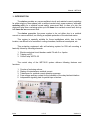
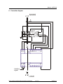
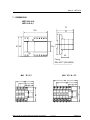
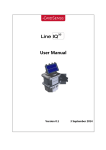
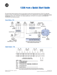
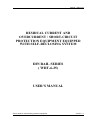
Manual - WRT-6-25
RESIDUAL CURRENT AND
OVERCURRENT / SHORT-CIRCUIT
PROTECTION EQUIPMENT EQUIPPED
WITH SELF-RECLOSING SYSTEM
DIN RAIL SERIES
( WRT-6-25)
USER’S MANUAL
User’s guide for self-reclosing protection equipment
Version 1.1
Manual – WRT-6-25
USER’S GUIDE FOR
SELF-RECLOSING PROTECTION EQUIPMENT
1. Introduction
2. Equipment description
2.1 Residual current protective system.
2.2 Overcurrent and short-circuit protective
system.
2.3 Tripping coil F3
3. Operation mode
4. General specifications
4.1 Circuit breaker of M41 series
4.2 Relay WRT-6-25
4.3 Tripping coil F3
5. Safety warnings
6. Connection diagram
7. Dimensions
User’s guide for self-reclosing protection equipment
2 of 11
Version 1.1
Manual - WRT-6-25
1.- INTRODUCTION
The device provides an overcurrent/short-circuit and residual current protection
for either single or three-phase (with or without neutral wire) power systems, with selfreclosing ability for a residual current and/or overcurrent fault. In case of a trip, the
electronic relay tries a reclosing action up to 10 times for a residual current fault, and up
to 2 times for an overcurrent fault.
The device guaranties the power system to be cut either due to a residual
current or overcurrent fault, so offering a complete protection of the electrical mains.
This system is specially suitable for those installations which, due to their
location, are difficult to be controlled: cooling chambers, facilities at countryside, etc.
This protection equipment with self-reclosing system for DIN rail mounting is
basically formed by following elements:
1. Electric-motorized circuit breaker model FA with 2 or 4 poles.
2. Tripping coil F3
3. Control relay WRT-6-25
The control relay of the WRT-6-25 system delivers following features and
functions:
1.
2.
3.
4.
5.
Index
Counter of reclosing actions.
Display of instantaneous residual current.
Transformer for residual current detection purposes.
Free-voltage auxiliary contact for the indication of the relay latched situation.
Independent signaling leds for partial trips or latches.
1 of 13
Version 1.1
Manual – WRT-6-25
2.- EQUIPMENT DESCRIPTION
2.1.- Residual current protective system
Two types are distinguished according to the rated sensitivity of the residual current
protection system:
•
•
Code 550 554
Code 550 555
-
WRT-6-25 -0,03 , rated sensitivity, I∆N= 30 mA
WRT-6-25.0,3 , rated sensitivity, I∆N= 300 mA
The frontal cover incorporates three push-buttons, one display and diverse signaling
leds.
Two terminals marked as E1/E2 in the lower part of the WRT-6-25 relay provides an
optional indication of the locked situation of the equipment once the maximum allowable
number of reclosing attempts is reached, either by residual current or overcurrent/shortcircuit fault.
Push-buttons description:
Test: Test to check the residual protection system out.
Reset: Reclosing of the relay and reset to zero of internal counters of reclosing
actions.
Select: Change of display values.
Display functions:
-
No. of reclosing actions. (Rd led)
Instantaneous value of the measured residual current. (Cd led)
User’s guide for self-reclosing protection equipment
4 of 11
Version 1.1
Manual – WRT-6-25
Description of signaling leds:
Sign
Power
OFF
Em
Ed
3-digit display
Cd
Rd
Led description
Power supply
Residual current &/or overload &/or short-circuit fault
Indication of the circuit breaker status:
Fixed on: latched situation after 2 reclosing attempts by overload
&/or short-circuit trip.
Indication of the residual current relay status:
Fixed on: latched situation after 10 reclosing attempts by residual
current trip.
Indication of the total number of reclosing actions.
Indication of instantaneous residual current (the value keeps in
display after the relay sensitivity has been exceeded)
When ON the display shows the residual current value.
when ON the display shows the total number of reclosing actions.
2.2.- Overcurrent and short-circuit protective system
M41 Series: Range from 6 to 63 A
The electric-motorized circuit breaker guarantees the effective protection against
overcurrent or short-circuit (10 kA DIN VDE). These circuit breakers can be either
single-phase or three-phase plus neutral type.
The circuit breaker can be closed or open either directly over the own circuit
breaker or by means of a command given by the relay.
After a trip due to an overload or a short-circuit event, the circuit breaker will
automatically switch to its ON position back (up to 2 attempts) provided the fault in the
installation has disappear once passed the set delay time (1 min).
The circuit breaker can be manually reclosed at any time just pressing the button
RESET in the relay.
The circuit breaker motor incorporates:
-
A yellow lever which permits the circuit breaker to be locked once it has been
opened, in order to avoid this could be neither mechanically or manually put
to the OFF position back. The circuit breaker can also be locked in the OFF
position by means of a padlock (6 mm ∅ passing hole).
User’s guide for self-reclosing protection equipment
5 of 11
Version 1.1
Manual – WRT-6-25
-
A set of auxiliary contacts to inform about the circuit breaker status. A closed
contact means that the circuit breaker is in the OFF position.
SPECIFICATIONS OF M41 SERIES
- Rated current In (A)
6 - 10 - 16 -20 - 25 - 32 - 40 - 50 - 63
- Rated operation voltage Un
240 V / 415 V~
- Breaking capacity
10,000 A (DIN VDE 0641/6.78).
- Number of poles
1/ 2/ 3/ 4
- Tripping characteristics
C type curve.
- Rated operation frequency
50/60 Hz
- IP degree
IP 40 (DIN 40050)
- Storage temperature
- 55 ºC to +55 ºC
- Operation temperature
- 25 ºC to +55 ºC
- Case colour
RAL 7035
2.3.-Tripping coil F3
The tripping coil F3 is an emission type
coil powered at 230 V~.
This coil enables a quick and safety trip
of the circuit breaker when this receive the
pertinent command from the residual current
relay WRT-6-25 in case of a residual current
fault event.
User’s guide for self-reclosing protection equipment
6 of 11
Version 1.1
Manual – WRT-6-25
3.- OPERATION MODE
Features of the WRT-6-25 as a residual current protective device:
- Built-in measuring differential transformer, inner diameter of ø 25 mm.
- Sensitivity set at 30 mA or 300 mA (adjustable in factory).
- Delay time between successive reclosing actions set at 1 minute.
- Allowable number of reclosing attempts set at 10.
- Period of 30 minutes to be waited before the internal counter of reclosing actions is
reset to zero.
Features of the WRT-6-25 as a overcurrent/short-circuit protective device:
- Allowable number of reclosing attempts set at 2.
- Delay time between successive reclosing actions set at 1 minute.
- Period of 30 minutes to be waited before the internal counter of reclosing actions is
reset to zero.
The electric-motorized circuit breaker guarantees the effective protection against
overcurrent or short-circuit (10 kA DIN VDE). These circuit breakers can be either
single-phase or three-phase plus neutral.
The circuit breaker can be closed or open either directly over the own circuit
breaker or by means of a command given by the relay.
After a trip due to an overload or a short-circuit event, the circuit breaker will
automatically switch to its ON position back (up to 2 attempts) once passed the set
delay time (1 min).
The circuit breaker can be manually reclosed at any time just pressing the button
RESET in the relay.
The circuit breaker motor incorporates:
-
A yellow lever which permits the circuit breaker to be locked once it has been
opened, in order to avoid this could be neither mechanically or manually put
to the OFF position back. The circuit breaker can also be locked in the OFF
position by means of a padlock (6 mm ∅ passing hole).
-
A set of auxiliary contacts to inform about the circuit breaker status. A closed
contact means that the circuit breaker is in the OFF position (short-circuit,
overload or manual disconnection).
User’s guide for self-reclosing protection equipment
7 of 11
Version 1.1
Manual – WRT-6-25
4. - GENERAL SPECIFICATIONS
4.1 Circuit breaker of M41 series
Operation rated voltage
Rated current, IN (A)
230 VAC 2 wires
400 / 230 VAC III+N
6 - 10 - 16 - 20 -25 -32 - 40 - 63
4.2 Relay WRT-6-25
Auxiliary voltage
Built-in differential transformer
Residual current, I∆N
3-digit display
Allowable number of reclosing actions in
case of trip by residual current fault
Allowable number of reclosing actions in
case of trip by overcurrent/short-circuit
fault
Delay time between reclosing actions
Time period to be waited before the
internal counter of reclosing actions is
reset to zero, once the power supply has
been restored and no other fault event
occurs in the meantime.
TEST Push-button
RESET Push-button
SELECT Push-button
Operation temperature
Storage temperature
Auxiliary signal (Terminals E1-E2)
User’s guide for self-reclosing protection equipment
230 V a.c.
Diameter of 25 mm.
30 or 300 mA, adjustable in factory
Counter of reclosing actions
Visualization of the instantaneous
residual current, and hold in display in
case of trip by residual current fault.
10 reclosing actions
reclosing actions
1 minute
30 minute
Test to the residual current protective
system.
To reclose the system and reset to zero
the counter of reclosing actions.
Switch of the visualization mode
between the number of reclosing
actions and the value of the residual
current.
0º to 45º C
-15º to + 60º C
NO free-voltage contact relay for the
indication of a complete locked
situation of the equipment either for the
residual current or overcurrent/shortcircuit reclosing system.
8 of 11
Version 1.1
Manual – WRT-6-25
4.3 Tripping coil F3
Operation voltage
230 VAC
5. - SAFETY WARNINGS
5.1 - Circuit breaker M41:
- Repetitive switching ON-OFF actions may give rise to a high heating level, and
even, a damage of the remote control system.
- After all reclosing attempts are completed, the fault in the installation must be
solved before the circuit breaker is again manually switched ON.
- When the downstream installation is being manipulated, the yellow lever of the
FA circuit breaker must be continuously placed in the OFF position to avoid not
controlled reclosing actions to occur.
5.2. - Residual current protective relay:
-
The TEST push-button permits the user to check the correct operation of both
the relay and the circuit-breaker.
-
The RESET push-button enables:
-
Resetting to zero the internal counter of total reclosing actions.
Reclosing at any time the residual current and overcurrent/short-circuitprotective system.
User’s guide for self-reclosing protection equipment
9 of 11
Version 1.1
Manual – WRT-6-25
6. - Connection diagram
MAINS
C1
1 3
U>
C2
05 06
06 08 96 98
H/S
2 4
M
H
05
N
On
Off
L1
L0
95
On Off C1
E1 E2
A1
A2
Latching
signal
LOAD
User’s guide for self-reclosing protection equipment
10 of 11
Version 1.1
Manual – WRT-6-25
7. - DIMENSIONS
WRT-6-25-0,03
WRT-6-25-0,3
75
105
87 85
70
45
25
Fixing :
DIN 46277 (EN 50022)
M41 2P+ F3
User’s guide for self-reclosing protection equipment
M41 3P + N + F3
11 of 11
Version 1.1