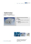
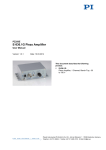
Download User Manual PZ69E - Physik Instrumente
Transcript
T e c h n i c a l
D o c u m e n t a t i o n
Operating Manual PZ 69E
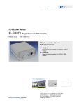
E-663
LVPZT Amplifier
Release 2.1.0
Product Description
and
Operating Notes
This document is valid for the following product:
E-663.00
Three-Channel Amplifier for Low Voltage PZTs
Release:
Release Date:
2.1.0
2004-01-09
© Physik Instrumente () GmbH & Co. KG
76228 Karlsruhe, Germany
EMail: [email protected]
FAX: (+49)721-4846-299
www.pi.ws
E-663.00 LVPZT Amplifier
User Manual PZ 69E
Table of Contents:
0. Manufacturer Declarations
3
0.1.
Declaration of Conformity ...............................................................3
0.2.
Quality and Warranty Clauses ........................................................3
0.3.
Warnings and Safety Notes ............................................................4
1. Introduction
4
2. E-663 General Description
5
2.1.
Operating and Display Elements : ..................................................5
2.2.
Line Power and Fuses ....................................................................6
3. Modes of Operation
7
4. Starting Operation
7
5. E-663 Technical Data
8
6. Frequency Response Curves
8
© Copyright 1996-2004 by Physik Instrumente (PI) GmbH & Co. KG
Release: 2.1.0
File:E-663_User_PZ69E210.doc, 360960 Bytes
Release 2.1.0
www.pi.ws
Page 2
E-663.00 LVPZT Amplifier
User Manual PZ 69E
0. Manufacturer Declarations
0.1. Declaration of Conformity
The manufacturer,
Physik Instrumente (PI) GmbH & Co. KG
Auf der Römerstr. 1
76228 Karlsruhe, Germany
declares, that the E-663.00 device complies with these specifications:
EMC: EN55022 (1991), Class B
EN50082-2 (3/93) / IEC 801-2
(8 kV Contact Discharge)
EN50082-1 (3/93) / IEC 801-3
(10 V / m)
EN50082-1 (3/93) / IEC 801-4
(2 kV )
ENV50141 / IEC 801-6
(10 V)
The product complies with the requirements of the EMC Directive 89/336/EEC and the
CE markings have been affixed on the devices.
0.2. Quality and Warranty Clauses
Certification
Physik Instrumente (PI) certifies that this product met its published specifications at
the time of shipment. The device was calibrated and tested with the PZT actuators
specified in the product identification table (see below).
Warranty
This Physik Instrumente product is warranted against defects in materials and
workmanship for a period of one year from date of shipment. Duration and
conditions of warranty for this product may be superseded when the product is
integrated into (becomes a part of) other Physik Instrumente products. During the
warranty period, Physik Instrumente will, at its option, either repair or replace
products which prove to be defective.
Limitation of Warranty
The foregoing warranty shall not apply to defects resulting from improper or
inadequate maintenance by the Buyer, Buyer supplied products or interfacing,
unauthorized modification or misuse, operation outside of the environmental
specifications for the product, or improper site preparation or maintenance.
The design and connection of any circuitry to this product is the sole responsibility
of the Buyer. PI does not warrant the Buyer's circuitry or malfunctions of PI
products that result from the Buyer's circuitry. In addition, PI does not warrant any
damage that occurs as a result of the Buyer's circuit or any defects that result from
Buyer-supplied products.
No other warranty is expressed or implied. Physik Instrumente specifically
disclaims the implied warranties of merchantability and fitness for a
particular purpose.
Release 2.1.0
www.pi.ws
Page 3
E-663.00 LVPZT Amplifier
User Manual PZ 69E
0.3. Warnings and Safety Notes
Warning: High Voltage
The PZT driver described in this document is power amplifier
that outputs high voltages which can generate lethal currents.
We strictly advice you to not open the chassis when line voltage
is connected. When using PZT translators with bare contacts,
never touch the conductors. Even if the PZT is not connected to
the driver, the ceramic may be charged up to high voltage!
Be aware of the risk of injury if not following general accident
prevention regulations!
1. Introduction
E-663 is a bench-top amplifier for driving three low-voltage piezoelectric translators
(LVPZTs). It offers three independent output channels capable of outputting and
sinking a peak current of 140 mA and an average current of 60 mA each.
The output voltage range covers -20 to +120 Volts that can be controlled manually
via front panel potentiometers or by analog control signals.
Three 3½-digit LEDs display the output voltage.
E-663 LVPZT amplifiers can be used for static and dynamic applications. The
excellent output stability and linearity allow the device to be used with highresolution positioning systems.
E-663.00 features:
• 3 x 14 W Peak Power
• 3 independent channels
• 3 x 3½-Digit Displays
Release 2.1.0
www.pi.ws
Page 4
E-663.00 LVPZT Amplifier
2.
User Manual PZ 69E
E-663 General Description
E-663 PZT drivers have three individual amplifier channels to drive three LVPZTs.
Each channel is equipped with a 10-turn potentiometer for manual control of the
output voltage (DC-offset setting).
External analog control signals can be connected to the BNC sockets on the front
panel.
The current output voltages are shown on a 3½-digit LED displays.
2.1. Operating and Display Elements :
(1)
(2)
(3)
(4)
(6)
Three 3½ -digit LED Display
Three LEMO output sockets
Three BNC input sockets
Three DC-Level potentiometers
Line switch/fuse assembly on the rear panel
E-663 LVPZT-AMPLIFIER
VOLTS
CH 1
0123
0123
CH 2
DC-OFFSET
CH 3
DC-OFFSET
DC-OFFSET
CH 1
CH 2
CH 3
CONTROL
INPUT
CONTROL
INPUT
CONTROL
INPUT
-2...12 V
-2...12 V
-2...12 V
PZT
PZT
-20...120 V
Release 2.1.0
-20...120 V
www.pi.ws
PZT
-20...120 V
Page 5
E-663.00 LVPZT Amplifier
User Manual PZ 69E
2.2. Line Power and Fuses
The power connection, input voltage selection and line
fuses are located on the rear panel. Unless you
request a specific setting, the unit will be set up for the
line voltage we believe predominant in your country.
New Fuses Required when Changing
Supply Voltage
To connect the product to a different supply voltage, it
is necessary not only to reorient the fuse carrier so that
the desired voltage is visible in the window, but also to
replace both the line fuses with the value appropriate
for the new voltage. Lower supply voltage requires
higher current.
To access the fuse carrier, remove the power cord,
and pry open the door that covers the carrier. The
carrier can then be pried out, exposing the two line
fuses (see illustration at right).
After replacing the fuses, reinstall the carrier in the new
orientation; check that the correct voltage setting is
visible through the window in the door when it is
reclosed.
Voltage Setting & Fuse Values:
115 V: 1.6 A*
230 V: 0.8 A*
Fuse location (1 of 2
fuses visible) and line
voltage setting
* slow blow fuses required
Release 2.1.0
www.pi.ws
Page 6
E-663.00 LVPZT Amplifier
3.
User Manual PZ 69E
Modes of Operation
E-663 LVPZT Amplifiers can be operated in 2 ways:
1. Manual, static operation:
The output voltage for each channel is set by a 10-turn potentiometer (DC-Offset)
in the range of 0 to +100 Volts.
2. External, static and dynamic operation:
The output voltage for each channel is controlled by analog signals ranging from -2
to +12 V applied to the BNC inputs, ranging. Multiplying by the gain factor of 10, an
output voltage of -20 to +120 V results. In this mode, the DC-offset potentiometer
allows for continuous shifting of the input voltage range between -2 to +12 V.
4.
Starting Operation
Warning: High Voltage
The PZT driver described in this document is power amplifier
that outputs high voltages which can generate lethal currents.
We strictly advice you to not open the chassis when line voltage
is connected. When using PZT translators with bare contacts,
never touch the conductors. Even if the PZT is not connected to
the driver, the ceramic may be charged up to high voltage!
Be aware of the risk of injury if not following general accident
prevention regulations!
Before you power up the E-663, check whether the AC operating voltage is set to
the right value (verify the specified line voltage at the rear panel).
Check basic operation of the E-663 functions without any PZT translators
connected. Select any of the channels and set the corresponding DC offset
potentiometer. The value read from the display represents the actual output
voltage. Turning the potentiometer from one end to the other should cause the
voltage reading to range from 0 to +100 Volts.
Turn the DC-OFFSET potentiometers counterclockwise (CCW) to zero the output
before you connect PZT translators to the LEMO output sockets. Otherwise the
translator may expand abruptly and connected parts could be damaged.
After the device is powered on, the displacements of the PZTs can be controlled
by using the DC OFFSET potentiometers, either exclusively or in conjunction with
the analog input signals.
Release 2.1.0
www.pi.ws
Page 7
E-663.00 LVPZT Amplifier
5.
6.
User Manual PZ 69E
E-663 Technical Data
Function:
Channels:
Output voltage range
Control signal input range:
Voltage Gain:
Amplifier for low-voltage PZTs
3
-20 to +120 V
-2 to +12 V
10 (+/- 0.1)
Peak output current (< 5 ms):
Average output current (> 5 ms):
Current limitation:
Max output power:
Average output power:
140 mA / channel
60 mA / channel
short-circuit-proof
14 W / channel
6 W / channel
DC offset setting:
Input impedance
0 to +100 V (with 10-turn potentiometer)
100 kOhm
Display:
Control input sockets:
PZT voltage output sockets:
3 x 3½-digit LED
BNC
LEMO ERA.00.250.CTL
Dimensions:
Operating voltage:
288 x 235 x 103 mm
selectable: 90 to 120 or 220-240 VAC, 50-60 Hz (linear P/S)
Frequency Response Curves
Electrical capacitance of connected translators:
P-810.10
0.5 µF
P-810.30
1.4 µF
P-840.30
5.4 µF
P-810.20
0.9 µF
P-840.10
1.8 µF
P-842.60
10 µF
P-844.60
45 µF
P-810.30
1.4 µF
P-844.30
22 µF
Release 2.1.0
www.pi.ws
Page 8


