1
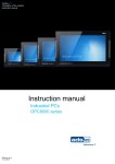
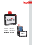
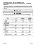
DC/AC INVERTER UNV-C USER MANUAL Eltek_UM_UNV-C_E_R3.0 DC/AC Inverter UNV-C User Manual Page 2 (32) Notes to this manual ATTENTION! Read this manual very carefully before installing and commissioning the specified module. This manual is a part of the delivered module. Familiarity with the contents of this manual is required for installing and operating the specified module. The rules for prevention of accidents for the specific country and the general safety rules in accordance with IEC 364 must be observed. The function description in this manual corresponds to the date of publishing. Technical changes and changes in form and content can be made at any time by the manufacturer without notice. There are no obligations to update the manual continually. The module is manufactured in accordance with applicable DIN and VDE standards such as VDE 0106 (part 100) and VDE 0100 (part 410). The CE marking on the module confirms compliance with EU standards 2006-95-EG (low voltage) and 2004-108-EG (electromagnetic compatibility) if the installation and operation instructions are followed. Supplier: FAX Email Internet ELTEK DEUTSCHLAND GmbH BU Industrial Schillerstraße 16 D-32052 Herford + 49 (0) 5221 1708-210 + 49 (0) 5221 1708-222 [email protected] http://www.eltek.com Please note: No part of this document may be reproduced or transmitted in any form or by any means -electronic or mechanical, including photocopying and recording- for whatever reason without the explicit written permission of Eltek Deutschland GmbH. Changes and errors excepted. 2011. ELTEK DEUTSCHLAND GmbH. All rights reserved. ©2011. ELTEK DEUTSCHLAND GmbH. Eltek_UM_UNV-C_E_R3.0 DC/AC Inverter UNV-C User Manual Page 3 (32) The current revision status of this manual is the following: Revision: 3.0 Date: 2009-05-11 Revision Description of change Writer Date 1.0 Basis is the former edition “BHB.UNV-C.D65-1000.HB102”; EVI RTH layout inserted, new revision numbering (X.X) introduced. 2008-11-10 2.0 Section “Error indication on the displays” inserted. RTH 2009-04-23 3.0 Sections 6.2.3 “Output” and 6.3.2 “Output Voltage MonitorRTH ing” corrected. 2009-05-11 ©2011. ELTEK DEUTSCHLAND GmbH. Eltek_UM_UNV-C_E_R3.0 DC/AC Inverter UNV-C User Manual Page 4 (32) Table of Contents A. Safety Instructions ............................................................................................................ 5 B. Electronic Waste Disposal ................................................................................................ 5 1. General Information ........................................................................................................... 6 2. Type Range (Standard) ..................................................................................................... 8 3. Storage ................................................................................................................................. 8 4. Commissioning .................................................................................................................... 9 5. Handling ............................................................................................................................ 11 5.1 Front view ................................................................................................................................................ 11 5.2 LED indication.......................................................................................................................................... 11 5.3 Adjustment keys .................................................................................................................................... 12 6. Functions........................................................................................................................... 13 6.1 Schematic Block Diagram ..................................................................................................................... 13 6.2 Functional Description........................................................................................................................... 14 6.2.1 Safe Electrical Decoupling ............................................................................................................ 14 6.2.2 Input .................................................................................................................................................. 14 6.2.3 Output ............................................................................................................................................... 15 6.2.4 Dynamic Regulation of Output Voltage ...................................................................................... 15 6.2.5 RFI-Suppression ............................................................................................................................... 15 6.3 Monitoring ................................................................................................................................................ 15 6.3.1 Input Voltage Monitoring ............................................................................................................... 15 6.3.2 Output Voltage Monitoring ........................................................................................................... 15 6.3.3 Monitoring of Overheating ............................................................................................................ 16 6.3.4 Signals............................................................................................................................................... 16 6.3.5 Adjustment of Output Parameters and Monitoring Thresholds ............................................ 16 6.3.6 Table “Adjustable Parameters” .................................................................................................... 20 6.3.6 CAN-Bus interface .......................................................................................................................... 21 7. Parallel Operation ............................................................................................................ 21 8. Electrical Connectors ..................................................................................................... 22 8.1 DC input voltage and signals ............................................................................................................... 22 8.2 AC output voltage .................................................................................................................................. 23 8.3 CAN-Bus Connector ............................................................................................................................... 23 9. Maintenance ..................................................................................................................... 24 10. Trouble Shooting .......................................................................................................... 24 10.1 No Output Voltage............................................................................................................................... 24 10.2 Distortion of Output Voltage ............................................................................................................. 24 10.3 Error indication on the displays ......................................................................................................... 25 11. Technical Specifications ............................................................................................. 27 11.1 Dimensional Drawings ......................................................................................................................... 29 12 Notes ................................................................................................................................ 30 ©2011. ELTEK DEUTSCHLAND GmbH. Eltek_UM_UNV-C_E_R3.0 DC/AC Inverter UNV-C User Manual Page 5 (32) A. Safety Instructions Warning! Because several components of operating electrical modules are charged by dangerous voltage, the improper handling of electrical modules may cause accidents involving electrocution, injury, or material damages. • Operation and maintenance of electrical devices must be performed by qualified skilled personnel such as electricians in accordance with EN 50110-1 or IEC 60950. • Install the device only in areas with limited access to unskilled personnel. • Before starting work, the device must be disconnected from mains. Make sure that the device is earthed. • Do not touch connector pins as they can be charged with dangerous voltage up to 30 seconds after disconnection. • Only spare parts approved by the manufacturer must be used. B. Electronic Waste Disposal The correct disposal of electronic waste is the responsibility to recycle discarded electronic equipment and is necessary to achieve the chosen level to protect human health and the environment. In the case of waste disposal of your discarded equipment we recommend to contact a professional waste management company. ©2011. ELTEK DEUTSCHLAND GmbH. Eltek_UM_UNV-C_E_R3.0 DC/AC Inverter UNV-C User Manual Page 6 (32) 1. General Information Inverters of type UNV-C (named UNV on next pages) are available for delivery with an output power of 1.2 and 2.5kVA per module. To increase the system output power several units can be operated in parallel. Typical applications are: • • AC power supply with input side battery buffering Industrial modular UPS with input side rectifier and battery DC-Input rectifier Picture 1.1: UNV in parallel operation Battery UNV UNV AC distribution Inverter UNV-C converts input side DC voltage to stable sinewave output voltage. Several output frequencies are available for delivery as option. UNV-C are hot-pluggable modules with rear side connectors. Only the communication wire (CANBus) is connected on the front. The inverter is controlled and monitored by internal microprocessor. All main functional parameters are adjustable with front side operating keys and are indicated with digital displays. Due to the excellent overall efficiency (see technical data) the unit has very compact dimensions (19”- cassette for mounting in 19” subracks), low weight and very high power density. Due to the special input side regulation principle the ripple voltage limit fulfils the standard of CCITT-A-filtering without any additional filter elements. To increase the reliability the inverter is designed to operate together with static bypass switch UNB. The static bypass switch monitores the connected bypass mains and synchronises the inverter output with mains frequency. In inverter preselection mode the UNB transfers the load supply to bypass mains in case of inverter faults, high overload, battery low voltage. The transfer is nearly without voltage interruption. After problem solving the unit switches back to inverter operation automatically. In case of mains preselection mode the inverter will take over the load if mains is not present, out of limits or heavy disturbed. ©2011. ELTEK DEUTSCHLAND GmbH. Eltek_UM_UNV-C_E_R3.0 DC/AC Inverter UNV-C User Manual Page 7 (32) The primary source is programmable on static switch unit. For the UNB a separate manual is available for delivery. DC-Input rectifier Picture 1.2: Inverter operation with static bypass switch UNB AC-Input Mains Inverter UNV UNV UNB Static bypass switch Battery BS Manual bypass switch AC distribution ©2011. ELTEK DEUTSCHLAND GmbH. Eltek_UM_UNV-C_E_R3.0 DC/AC Inverter UNV-C User Manual Page 8 (32) 2. Type Range (Standard) Type Designation Article Code Input voltage in VDC Output voltage in VAC Output power (VA @ cosφ=0.8) Dimensions W/H/D (mm) UNV48-1.2C 500-012-510.00 48 230 1200 142/262/285 UNV48-2.5C 500-025-510.00 48 230 2500 142/262/405 UNV60-1.2C 500-012-610.00 60 230 1200 142/262/285 UNV60-2.5C 500-025-610.00 60 230 2500 142/262/405 UNV110-1.2C 500-012-710.00 108 230 1200 142/262/285 UNV110-2.5C 500-025-710.00 108 230 2500 142/262/405 Available options and accessory parts • • • Additional connector 19”-subrack connector fastening 3. Storage The modules must be stored in a dry, dust free environment in accordance with the specified storage temperature (see technical specifications; section 11). ©2011. ELTEK DEUTSCHLAND GmbH. Eltek_UM_UNV-C_E_R3.0 DC/AC Inverter UNV-C User Manual Page 9 (32) 4. Commissioning After unpacking the module check for damages based on external influences. In case of mechanical deformation do not put the module in operation. The module is to be mounted into the subrack with four frontside screws. Please check the input voltage level and compare it with the type lable value on the inverter module before connecting DC voltage. Picture 4.1: 19“subrack with UNV-C Inverter For mounting the units at operation site following instructions and rules have to be observed: • mount in dry, dustfree rooms only • observe the specifications about ambient conditions such as ambient temperature or relative humidity • highly dusty or aggressive chemical atmosphere is not allowed; dew and dust in combination can cause short circuits on printed circuits • sufficient air cooling is required, especially when mounting in cabinets with several 19“ subrack levels Check mains voltage before connecting the inverter (observe nominal values on type label). For connection of DC input and AC output the front panel connectors (X1) and (X2) have to be used. The DC input is protected against wrong polarity (unit does not switch on). The UNV is equipped with input and output fusing (MCB`s on front panel). The inverters operate with temperature controlled fan cooling. The ambient temperature must be lower than 40 °C. Please check the load power before connecting the module. A permanent overload is not allowed and decreases the inverters lifetime. Especially the inrush currents of loads have to be observed (for instance, a usual computer monitor can have an inrush current of more than 50A!). ©2011. ELTEK DEUTSCHLAND GmbH. Eltek_UM_UNV-C_E_R3.0 DC/AC Inverter UNV-C User Manual Page 10 (32) The connection of the none-fused earthed conductor is required. The electrical connections have to be carried out acc. pin list in section 8. Please use wires acc. VDE 0100 or equal standard. To decrease voltage losses on cables usage of bigger sizes of wire as specified is recommended. For instance, a high voltage loss on battery wires can decrease the backup time. Following installation rules should be observed: Single inverter: • • • • • • • check system wiring (polarity of DC- supply line) check that the inverter is switched off connect DC input with open DC busbar fuses connect AC loads close DC busbar fuses switch on the unit with front side MCB switch on load Inverters in parallel: • • • • • • • • check system wiring (polarity of DC- supply line, synchronous bus) check that the inverters are switched off connect DC input with open DC busbar fuses check wiring between inverters (synchronization wires) connect AC loads close DC busbar fuses switch on the units with front side MCB’s switch on load One unit operates as master and synchronizes all other units. NOTE: The unit which transmits the synchonization signal to the synchronization bus at first will be the master. If this master unit is disturbed or switched off, another unit overtakes the master function. In systems with static bypass switch (SBS) the inverters are synchronized by the SBS unit. ©2011. ELTEK DEUTSCHLAND GmbH. Eltek_UM_UNV-C_E_R3.0 DC/AC Inverter UNV-C User Manual Page 11 (32) 5. Handling All operating elements are located on the front of the module. The input and output side MCB’s are used as ON/OFF-switch. The LED’s indicate the operation state of inverter. All signals and monitorings are described in the following sections. 5.1 Front view Picture 5.1: Front view UNV-C 5.2 LED indication The following table shows the LED status signals: LED OPERATION Uo Color green green Ui> red Ui< red Io> red T> red ALARM red Meaning Inverter is switched on and operates Inverter output voltage o.k. (see section 6.3.5) Input voltage high; input voltage > Adjusted monitoring threshold; inverter switches off (see section 6.3.5) Input voltage low; input voltage < Adjusted monitoring threshold; inverter switches off (see section 6.3.5) Output current high; short circuit or overload on output Continously light: overheating of inverter by overload Blinker light: poor cooling; Inverter switches off delayed Collective failure, delay time of relay alarm adjustable, relay contact on X1; all single errors are included ©2011. ELTEK DEUTSCHLAND GmbH. Eltek_UM_UNV-C_E_R3.0 DC/AC Inverter UNV-C User Manual Page 12 (32) 5.3 Adjustment keys The adjustment takes place with up/down keys located at the front panel of the inverter while the displays indicate the actual values. Front keys Designation Operation up down during menu item selection: change to previous item (parameter) during adjustment mode: increase value during menu item selection: change to next item (parameter) during adjustment mode: decrease value For switching between the menues press both buttons for approx. 3 seconds. ©2011. ELTEK DEUTSCHLAND GmbH. Eltek_UM_UNV-C_E_R3.0 DC/AC Inverter UNV-C User Manual Page 13 (32) 6. Functions 6.1 Schematic Block Diagram Picture 6.1: Schematic Block Diagram Inverter UNV (C type) ©2011. ELTEK DEUTSCHLAND GmbH. Eltek_UM_UNV-C_E_R3.0 DC/AC Inverter UNV-C User Manual Page 14 (32) 6.2 Functional Description Inverters of the UNV-type are new switch mode inverters with an innovative operation principle. The inverter transforms the input side DC voltage into an AC voltage with high stability concerning frequency, amplitude and waveshape. The unit consists of following main parts: 1. Connector SUB-MIN-D 21 WA 4 / Cliffcon 4PC/S (1.2kVA-2.5kVA) to connect input, output voltage and signals 2. Passive filter to reduce RF interferences 3. Input circuit breaker (MCB); used as ON/OFF switch 4. Innovative DC/DC converter topology consisting of MOSFET/IGBT converter, isolation transformer, rectifier bridge to produce a voltage of approx. 380VDC, capacitor block to store the DC voltage. The DC/DC-converter modulates the input current to suppress the input AC component. 5. Pulse width modulated inverter bridge (20kHz) with IGBT`s to convert the DC voltage to an AC voltage with high frequency and amplitude stability 6. Monitoring system for input, output and internal parameters 7. Output relay (necessary for parallel operation) 8. Output circuit breaker (MCB), mechanically coupled with DC circuit breaker 9. Output AC filter for RFI suppression 10. Control board for DC/DC converter 11. Control board for AC converter 12. Microprocessor based control unit performs controlling, monitoring, adjustments (value storage) and displaying of inverters parameter and serial communication via CAN-Bus 6.2.1 Safe Electrical Decoupling The unit fulfills the standard EN60950. Observance of air and creeping distances, the isolation transformer and the separate wiring guarantee a safe electrical decoupling between primary (input) and secondary (output) side. 6.2.2 Input The DC input is protected by a magnetic circuit breaker (MCB). The input is equipped with inrush current limitation to limit the inrush current to the level of nominal input current. The input voltage and current is visible at the front side digital displays. ©2011. ELTEK DEUTSCHLAND GmbH. Eltek_UM_UNV-C_E_R3.0 DC/AC Inverter UNV-C User Manual Page 15 (32) 6.2.3 Output The unit is generally equipped with an output MCB. The output is sustained short circuit proof and supplies a short circuit current of 2 to 3 x Inom for three seconds. After that, the unit automatically switches off and tries to switch on again (for a maximum of three times) after 15 seconds. The inverter can be overcharged for a short time without switching off. The overload alarm is preset to 30% overload for 10 sec. After 10 seconds the unit automatically switches off. It must be manually restarted (manually switch off and switch on again). If the overload exceeds the preset overload value, the unit automatically switches off with delay of three seconds. 6.2.4 Dynamic Regulation of Output Voltage For load steps between 10% and 100% Inom/100% and 10% Inom the dynamic voltage deviation is < 3 % and is regulatedwithin <1.5 ms to static accuracy. 6.2.5 RFI-Suppression The UNV inverter UNV fulfills the standards EN 55011/55022 class „B“. 6.3 Monitoring 6.3.1 Input Voltage Monitoring The input voltage is continuously monitored. The actual value is compared with the programmed monitoring thresholds. The thresholds can be adjusted with the front keys (see section 6.3.5). The red LED "Ui<" signalizes inverter input voltage low (voltage is lower than adjusted threshold Ui<). The inverter switches off with an adjustable delay time. It switches on again if the input voltage is within the correct range. The switch-on voltage is adjustable. The hysteresis and delay time protects the unit against an oscillation of the automatic switch off function, e.g. if a discharged battery is unloaded by inverter switch off. The red LED "Ui>" signalizes inverter input voltage high (voltage is higher than adjusted threshold Ui>) The inverter switches off without delay time (protection against overvoltage). The inverter switches on again if the input voltage is lower than adjusted switch off threshold. 6.3.2 Output Voltage Monitoring The inverter output voltage is transmitted to the control unit by a voltage transformer and is compared to internally adjusted values. If there is a correct output voltage the green LED "Uo" is on. If the output voltage is lower than the adjusted threshold value (e.g. high overload or short circuit), the LED “ALARM” is on, whereas the LED “Uo” is off. If the output voltage is higher than the adjusted threshold value “Uo>” the unit automatically switches off (selflocking), the LED “ALARM” is on. The unit must be manually switched on. ©2011. ELTEK DEUTSCHLAND GmbH. Eltek_UM_UNV-C_E_R3.0 DC/AC Inverter UNV-C User Manual Page 16 (32) 6.3.3 Monitoring of Overheating If the internal temperature of the inverter is higher than the adjusted threshold value the LED “T>” is on. High ambient temperature, poor cooling, permanent overload (approx. 20-25%) or a defective fan can cause overheating of the unit. The inverter switches off with an adjustable delay time. The inverter switches on again if the temperature is lower than the adjusted switch on threshold. Additionally, the fan voltage and current characteristic is monitored to detect a defective fan. This is indicated by a blinking LED „T>“. 6.3.4 Signals All operation modes and error-states are indicated by LED’s which are fitted on the front panel. The collective failure signal is available by an isolated relay contact on connector X1. Max. contact load: 60VDC/1A; 110VDC/0.45A. In case of failure the contacts “COM” and “NC” are closed. 6.3.5 Adjustment of Output Parameters and Monitoring Thresholds The adjustment of output parameters and monitoring thresholds is easy. The values can be adjusted with the two frontkeys by displaying the actual value. The inverter offers two adjustment menus: • • Basic menu PM1 is available for all users Service menu PM2 is for service personnel only. PM2 has a code protection to protect against unallowed parameter changes. In the operation mode the top display shows the output voltage and the bottom display shows the output current. For adjustments of parameters in the basic menu PM1 the following procedure has to be used: 1. press both keys UP/DOWN (↑↓) together for short time; the inverter changes to the adjustment mode 2. press the key UP (↑) or DOWN (↓) to change the adjustment parameter (see the diagram on the next page) 3. press both keys UP/DOWN (↑↓) together for short time; the inverter changes to the value change mode 4. press the key UP (↑) or DOWN (↓) to change the adjustment value 5. press both keys UP/DOWN (↑↓) together for short time; the inverter changes back to the adjustment mode (the upper display shows a horizontal line, the changed value is stored at this moment) 6. press both keys UP/DOWN (↑↓) for approx. 3 sec. to change back to the operation mode For details concerning the adjustable parameters in PM1: see the diagram a) on the next page. ©2011. ELTEK DEUTSCHLAND GmbH. Eltek_UM_UNV-C_E_R3.0 DC/AC Inverter UNV-C User Manual Page 17 (32) Standard display during operation/monitoring of in -/output parameters: Outputvoltage Outputcurrent ©2011. ELTEK DEUTSCHLAND GmbH. Inputvoltage Inputcurrent Outputfrequency ο devicetemperature τ Input-power Restart and selftest Eltek_UM_UNV-C_E_R3.0 DC/AC Inverter UNV-C User Manual Page 18 (32) OutputComplex power ο 2.300 Output-Active power Power factor of the load Hardware-Reset Press both keys short! For switching to the adjustment menu press both buttons for approx. 3 sec (see next page). ©2011. ELTEK DEUTSCHLAND GmbH. Eltek_UM_UNV-C_E_R3.0 DC/AC Inverter UNV-C User Manual Page 19 (32) Adjust the values and thresholds as follows Outputvoltage ο Outputundervoltage Outputovervoltage Inputovervoltage Input undervoltdervoltage(restart) voltage Inputovervoltage You can leave the adjustment mode by pressing both keys for approximately three seconds. ©2011. ELTEK DEUTSCHLAND GmbH. Eltek_UM_UNV-C_E_R3.0 DC/AC Inverter UNV-C User Manual Page 20 (32) 6.3.6 Table “Adjustable Parameters” Following table shows the standard values (factory set), adjustment ranges and steps: Display1 Designation Factory set Range Step nominal value of output voltage Uo* 230 [VAC] 200...255 0,25 [V] monitoring threshold of output voltage low Uo<* 207 [VAC] 180...230 1,0 [V] Monitoring threshold of output voltage high Uo>* 253 [VAC] 230...270 1,0 [V] switch off threshold input voltage high Ui> switch off threshold input voltage low Ui< switch on again threshold input voltage low Ui< 48V: 75 [VDC] 108V: 130 48V: 41 [VDC] 108V: 92 48V: 45 [VDC] 108V: 96 0...80 0...135 41...80 90...110 41...80 90...110 0,1 [V] 0,25 0,1 [V] 0,25 0,1 [V] 0,25 *While the thresholds values Uo, Uo> are set with up/down keys, the moving dot shows the actual value: For example: 230 230. Corresponds to 230.0 Corresponds to 230.25 23.0 Corresponds to 230.5 2.30 Corresponds to 230.75 With each click at the UP/Down keys the dot moves. After four times clicking (4/4), the voltage value is increased (or decreased) for 1V. ©2011. ELTEK DEUTSCHLAND GmbH. Eltek_UM_UNV-C_E_R3.0 DC/AC Inverter UNV-C User Manual Page 21 (32) 6.3.6 CAN-Bus interface The inverter is equipped with a serial data interface according to CAN (= Controlled Area Network) -specification. Via CAN-Bus, several inverters in a system or parallel connection can be controlled and monitored by a central unit which is integrated into the static switch unit UNB. Following parameters of a specific inverter unit can be controlled or read out: • • • • • • • • Remote ON/OFF Inverter status (OK/failure) Output voltage (measurement value) Output current (TRMS measurement value) Input voltage (measurement value) Input current (measurement value) Output frequency (measurement value) Internal temperature (measurement value) The CAN-Bus connectors are located on the front panel. The wiring to the central unit shall be as shortes as possible. Cable length must not exceed 30m. 7. Parallel Operation ATTENTION! Before starting several units in parallel it is important to check the output frequency and voltage on each unit without any connections between the units. In the next step it has to be checked that the connections of the SYNC-BUS wires between the modules are correct. NOTE! The unit which transmits the synchonization signal to the synchronization bus at first is the master. If this master unit is disturbed or switched off, another unit overtakes the master function. In systems with static bypass switch (SBS) the inverters are synchronized by SBS unit. The inverter output relay switches the inverter output to AC busbar if the internal voltage is okay and the output voltage is within the correct range. On this way defective modules switch off themselves and are automatically disconnected from the AC bus. ©2011. ELTEK DEUTSCHLAND GmbH. Eltek_UM_UNV-C_E_R3.0 DC/AC Inverter UNV-C User Manual Page 22 (32) 8. Electrical Connectors 8.1 DC input voltage and signals X1 (SUB-MIN-D 21WA4) socket outlet (DC input voltage and signals): Picture 8.1: Connector X1 A1 A2 A3 10 1 17 9 A4 X1/Pin A1 A2 A3 A4 1 2 3 4 5 6 7 8 9 10 11 12 13 14 15 16 17 Designation DC input, plus pole DC input, plus pole (only 2.5kVA) DC input, minus pole (only 2.5kVA) DC input, minus pole No connection External switch ON/OFF (L+)1) Collective failure COM2) Collective failure NC Collective failure NO SYNC-STAT3) (synchronous bus state lines) SYNC-SIG4) (synchronous bus 50Hz-signal) SYNC-GND (synchronous bus ground) No connection No connection External switch ON/OFF (L-) No connection No connection No connection No connection No connection No connection External switch off by connecting of an external voltage of 12-24VDC between pin 2 and 11; input is free of potential with 500VDC – isolation to DC input 1) Relay contact with safe electrical decoupling to AC side and with 500VDC to DC; COM and NC are closed at error. The maximum load for the relay contacts is: I < 0.45ADC Umax = 110VDC Umax ≤ 60VDC I < 1ADC 2) ©2011. ELTEK DEUTSCHLAND GmbH. Eltek_UM_UNV-C_E_R3.0 DC/AC Inverter UNV-C User Manual Page 23 (32) 3) Connection between all inverters and SBS for operation with static bypass switch SBS 4) Connection between all inverters for parallel operation 8.2 AC output voltage X2 (Cliffcon 4PC/S) socket outlet (AC output voltage): 1 Picture 8.2: Connector X2 2 4 3 X2/Pin 1 2 3 4 Designation AC output, L1 No connection PE AC output, N 8.3 CAN-Bus Connector Connector (socket outlet RJ45, 6-pole): Picture 8.3: CAN-BUSInterface Pin Signal CAN1 Signal CAN2 1 CAN_V+ Voltage supply +8...15V 2 CAN_V+ Voltage supply +8...15V 3 CAN_H Signal (high) 4 CAN_L Signal (low) 5 CAN_V- Voltage supply Ground 6 CAN_V- Voltage supply Ground ©2011. ELTEK DEUTSCHLAND GmbH. Designation Eltek_UM_UNV-C_E_R3.0 DC/AC Inverter UNV-C User Manual Page 24 (32) 9. Maintenance In general, the inverter is maintenance-free. A yearly inspection with following checks is recommended: • • • • Correct fan operation Optical/mechanical inspection Removal of dust and dirt, especially on radiator surfaces Check for internal dust or humidity Attention! Dust together with dew or water can destroy the internal circuits by short circuit. Dust inside the unit can be blown out with dry compressed air. The intervals between this checks depends on ambient conditions of the installed module. 10. Trouble Shooting All works have to be done by qualified personnel only. 10.1 No Output Voltage • • • • • • • • DC input voltage O.K.? mains switch (MCB) on? green LED„Operation“ on? Is the DC input voltage properly connected? DC input fuse (on DC busbar) O.K.? signalling LED’s Ui> or Ui< on ? short circuit or overload on output? output fuse O.K.? If the unit still does not work even though all checks are done, please contact your sales agent or the service department of Eltek Deutschland. 10.2 Distortion of Output Voltage • • • • overload on output? - check and reduce the load! big inrush current of the load? distortions by load steps or current peaks? adjustment of voltage value Uo not correct? Adjust to the correct value If the unit still does not work even though all checks are done, please contact your sales agent or the service department of Eltek Deutschland. ©2011. ELTEK DEUTSCHLAND GmbH. Eltek_UM_UNV-C_E_R3.0 DC/AC Inverter UNV-C User Manual Page 25 (32) 10.3 Error indication on the displays Switch-off (shutdown of the module) caused by error is indicated on the displays. Example: Upper display: SHd = Shutdown Lower display: Error number (example „129“) Possible single error numbers are listed in the table below: Error number (decimal number) 1 2 4 8 16 32 64 128 Meaning Io> or Vi> Vi< or fan error Vo not ok (e.g. restart error) T> or input DC/DC converter not ok Internal error Switch off via CAN-Bus (e.g. by static bypass switch UNB) alternatively via external switch off. Vo> Vo< If more than one error appeared, the result (addition of the single error numbers) is shown at the lower display. The example above (error number „129“) is the result of error number „1“ plus error number „128“. For error numbers which include two possibilities (error number „1“, „2“ and „8“) please note the LED which additionally is “ON” for an identification of the error. A further example to clarify: Upper display: SHd = Shutdown Lower display: Error number (example „138“) Error number „138“ is the result of „128“ + „8“ + „2“. „2“ means “input under voltage” (LED „Vi<“ is ON) or “fan error” (LED „T>“ is blinking). „8“ means “over temperature” (LED „T>“ is ON) or “input DC/DC converter is not ok”. „128“ means „output under voltage”. Because the module has switched OFF there is no output voltage. Due to this, the error „output under voltage“ also is included. ©2011. ELTEK DEUTSCHLAND GmbH. Eltek_UM_UNV-C_E_R3.0 DC/AC Inverter UNV-C User Manual Page 26 (32) The following display indications are exceptions: At shutdown due to short circuit or overload the displays indicate the following: Upper display: SHd = Shutdown Lower display: ovL = short circuit/overload An intended shutdown via CAN-Bus by static bypass switch UNB is indicated as follows: Upper display: OFF (shutdown) Lower display: CAn (via CAN-Bus) An intended shutdown via external switch off (connected pins 2 & 11 according to section 8.1) is indicated as follows: Upper display: OFF (shutdown) Lower display: PIn (via external switch off) ©2011. ELTEK DEUTSCHLAND GmbH. Eltek_UM_UNV-C_E_R3.0 DC/AC Inverter UNV-C User Manual Page 27 (32) 11. Technical Specifications Nominal input voltage See type list (section 2) Input voltage range 48/60V types: 42-75VDC; 108V types: 77-138VDC Inrush current ≤ nominal input current Nominal output voltage 230VAC ±0.5% Adjustment range: 200...255VAC Output frequency 50Hz or 60Hz ±0.05%; synchronization range by external static switch unit 45-65Hz Nominal output power acc. to the type list (@ cos phi=0.8) Output power factor range 0.5 ind. – 1 – 0.5 cap. Total harmonic distortion <2% for linear load Overall efficiency up to 92% for 50...100% load Crest factor ≤3 RFI suppression / immunity CE-label (EN50081-1, EN55011/55022 class „B“ EN50082-2, EN61000-4 part 2/3/4/5) Isolation voltage acc. to EN60950 Reflected input voltage ripple ≤ 1.8mV psophometric (CCITT-A-filter) Dynamic bahavior ≤ 3 % for load transients between 10 % - 100 % 10 % of nominal output current (transient time ≤ 0.3 ms) Short circuit protection sustained short circuit proof, short circuit current 2-2,5x Inom for approx. 3sec. (with delayed restart) Monitoring DC-input voltage (UIN<, UIN>) with automatic switch ON/OFF function, AC-output voltage (UOUT); overtemperature (T>) and overload with automatic switch off function; fan monitoring Overload capability 130% for 10 sec. LED-Signals OPERATION, UOUT, UIN<, UIN>, IO>, T> and ALARM Relay contacts collective failure (max. contact load: 110VDC/0.5A; 60VDC/1A) Parallel operation max. seven units, load sharing approx. 5% Inom by degressive output characteristic ©2011. ELTEK DEUTSCHLAND GmbH. Eltek_UM_UNV-C_E_R3.0 DC/AC Inverter UNV-C User Manual Page 28 (32) Communication CAN-Bus interface for communication with static bypass switch UNB Noise emission ≤ 40dB(A) at 1m distance Dimensions acc. to the type list Mechanical construction acc. to VDE 0160 edition 5.88 section 7.2.2 Protection class IP20 Cooling speed controlled fan, monitored Ambient temperature operation: 0...+40°C; storage: -30...+65°C Max. installation altitude 1000m Surfaces powder coating RAL 7035 (front panel only); constructive parts: anodized metal Electrical connectors DC-Input and signals: SUB-MIN-D 21WA4 (frontside) AC-Output: Cliffcon 4PC/S (frontside) CAN-BUS: RJ45-Connector (frontside) Additional parts included in delivery Input + output connector ©2011. ELTEK DEUTSCHLAND GmbH. Eltek_UM_UNV-C_E_R3.0 DC/AC Inverter UNV-C User Manual Page 29 (32) 11.1 Dimensional Drawings Picture 11.1: Dimensional drawings ©2011. ELTEK DEUTSCHLAND GmbH. Eltek_UM_UNV-C_E_R3.0 DC/AC Inverter UNV-C User Manual Page 30 (32) 12 Notes ©2011. ELTEK DEUTSCHLAND GmbH. Eltek_UM_UNV-C_E_R3.0 DC/AC Inverter UNV-C User Manual Page 31 (32) Notes ©2011. ELTEK DEUTSCHLAND GmbH. Eltek_UM_UNV-C_E_R3.0 Supplier: FAX Email Internet ELTEK DEUTSCHLAND GmbH BU Industrial Schillerstraße 16 D-32052 Herford + 49 (0) 5221 1708-210 + 49 (0) 5221 1708-222 [email protected] http://www.eltek.com 2011. ELTEK DEUTSCHLAND GmbH. All rights reserved.