1
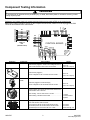
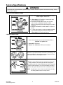
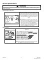
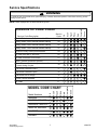
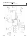
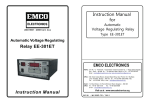
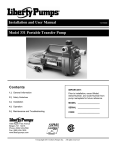
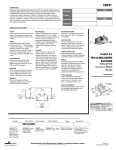
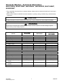
Domestic Washer—Technical Information
MAV551EEW*, MAV5758EW*, MAV5920AG*, MAV5920EW*, MAVT546EW*,
NAV8805EW*
• Due to possibility of personal injury or property damage, always contact an authorized technician for servicing or
repair of this unit.
• Refer to Service Manual 16026502 for detailed installation, operating, testing, troubleshooting, and disassembly
instructions.
!
CAUTION
All safety information must be followed as provided in this Technical Sheet and in Service Manual 16026502.
!
WARNING
To avoid risk of electrical shock, personal injury, or death, disconnect power to unit and discharge capacitor
before servicing, unless testing requires it.
Models
Power Source
Voltage AC
Amperage
Frequency
Motor horsepower
Cabinet Dimensions
Height−overall
Height with lid open
Height of cabinet
Width
Depth with rear assembly
Weight
Uncrated
Features
Wash cycles
Water temperatures
Water levels
Motor speed
Spin speed (revolutions per
minute)
Wash speed (oscillations per
minute)
Capacity
April 2006
©2006 Maytag Services
MAV551EEW*
NAV8805EW*
MAV5920AG*
MAV5758EW*
MAV5920EW*
MAVT546EW*
120 VAC
11.5 A
60 Hz
½
240 VAC
11.5 A
50 Hz
½
120 VAC
11.5 A
60 Hz
½
44”
1
53- /2”
36”
27”
27”
44”
1
53- /2”
36”
27”
27”
44”
1
53- /2”
36”
27”
27”
136 lbs.
136 lbs
136 lbs.
4
4
Infinite
2 speeds
413/620 rpm
5
4
Infinite
2 speeds
413/620 rpm
5
4
Infinite
2 speeds
413/620 rpm
58-88 opm
58-88 opm
58-88 opm
3.3 cubic feet
3.3 cubic feet
3.3 cubic feet
1
16026747
Component Testing Information
!
WARNING
To avoid the risk of electrical shock, personal injury, or death, disconnect power to unit before servicing, unless
testing requires power.
WH / YL
BU
WH / YL
YL / RD
RD / BK
BR
PU
BU
BK
8 7 6 5 4 3 2 1
4 3 2 1
PS1
5 4 3 2 1
PS6
PS4
PS5
15 13 11 9 7 5 3 1
GY
OR
YL
PU
PK
GY
BK
WH
CONTROL BOARD
HI/LO
SPEED
RE3
START
RE2
PS2
VIEW “A”
PS5
(EXPORT ONLY)
EXPORT WASHER
3
5
7
9
GY
GY
BK
WH
OR
YL
PU
PK
17 15 1311 9 7 3 1
1
11
13
15
DIRECTION
RE0
Illustration
Component
AC Power
PS11
PS10
RD
BR
PS9
BU
PS12
WH
PS8
OR
GY
PS7
PS
3
R E1
9 8 7 6 5 4 3 2 1
DOMESTIC WASHER
Resistance and voltage checks of components listed below can be made at PS5 on the control board.
Note: When making resistance checks on the components listed below, washer must be unplugged and PS5
connector disconnected from control board.
Test Procedure
With the unit plugged in, check source voltage at Pin #15
WH and Pin #13 BK of PS5 on the control board...............
Results
120 V AC
(240 V AC - Export)
Lid Switch
With the unit plugged in,
check voltage at Pin #5 YL and Pin #15 WH of PS5..........
120 V AC
(240 V AC - Export)
Pressure
Switch
With unit plugged in and the tub empty,
check voltage at Pin #3 OR and Pin #15 WH of PS5.........
Motor
Unplug washer, disconnect harness at PS5 and test from
wire insertion side of harness.
Run winding - PS7 GY and Pin #5 YL of PS5.....................
Start winding - PS9 BU and PS10 RD................................
Water Valves
16026747
120 V AC
(240 V AC - Export)
Unplug washer, disconnect harness and test resistance
from wire insertion side of harness.
(Hot valve) Pin #9 PK of PS5 and Pin #3 OR of PS5..........
(Cold valve) Pin #7 PU of PS5 and Pin #3 OR of PS5........
(Thermistor) Pin #1 GY and Pin #11 GY of PS5.................
2
1.5 ohms
4.0 ohms without
capacitor
1120 ohms
1120 ohms
53000 ohms @ 70F
April 2006
©2006 Maytag Services
Service Specifications
!
WARNING
To avoid the risk of electrical shock, personal injury, or death, disconnect power to unit before servicing, unless
testing requires power.
Fabric Selection
Soil Level - Approximate Agitation Times, in minutes
Light
Normal
Heavy
Extra Heavy
2
4
6
8
Intermittent
6
Intermittent
9
Intermittent
12
Intermittent
15
6
9
12
15
9
12
15
21
9
15
18
24
9
15
18
24
Quick Wash
Gentle/Fast
Hand Wash
Ex. Gentle/Slow
Delicates
Gentle/Slow
Permanent Press
Medium/Slow
Regular
Medium/Fast
Whites & Towels
Normal/Fast
Agitation Speeds
Gentle
58 opm (oscillations per minute)
Ex. Gentle
Intermittent 58 opm
Medium
Cycles between 3 minutes at 88 opm and 3 minutes at 58 opm
Normal
88 opm
Spin Speeds
Fast Spin
620 +/- 25 rpm (revolutions per minute)
Slow Spin
413 +/-17 rpm
April 2006
©2006 Maytag Services
3
16026747
Service Specifications
!
WARNING
To avoid the risk of electrical shock, personal injury, or death, disconnect power to unit before servicing, unless
testing requires power.
ENTER SERVICE MODE
Rotate the Cycle Selector Knob to the “Power Off”
position and press knob.
(All LED’s will be off).
Rotate the Cycle Selector Knob clockwise past
“Power Off” twice and stop at “Regular”.
(Watch LED’s, they will illuminate as the knob is
rotated).
Rotate the Cycle Selector Knob counterclockwise back
to “Regular” and press knob.
•
•
•
“Power Off”, “Rinse & Spin” LED will blink (if
error codes are present). “Regular” LED will be
illuminated.
Model I.D. is displayed by the LED’s around the
bottom of the dial; see ‘MODEL CODE CHART’.
Model I.D. can be redisplayed while in Service
Mode by setting knob to “Handwash” and
pressing; see ‘MODEL CODE CHART’ for Model
I.D.
EXIT SERVICE MODE
Rotate Cycle Selection Knob to “Power Off” and
press knob.
or
Allow 5 minutes of inactivity.
or
Disconnect power.
16026747
4
April 2006
©2006 Maytag Services
Service Specifications
!
WARNING
To avoid the risk of electrical shock, personal injury, or death, disconnect power to unit before servicing, unless
testing requires power.
DISPLAY/CLEAR SERVICE CODES
Enter ‘Service Mode’ then set Cycle Selection Knob to
“Rinse & Spin”. Press knob.
• “Rinse & Spin” LED will blink if codes other than
power interrupt are present.
• Press knob to view codes. Press once for each
code. Codes are displayed newest to oldest.
Machine beeps three times after last service code is
displayed.
• Refer to ‘DIAGNOSTIC CODE CHART’ for Service
Codes.
• To clear codes display a code then press and hold
Cycle Selection Knob until machine beeps twice.
“Rinse & Spin” LED will stop blinking.
CONSOLE SWITCH TEST
Enter ‘Service Mode’ then set Cycle Selection Knob to
“Delicate” and press knob.
• “Power Off” LED blinks.
• “Pause” and “Delicates” LED’s are illuminated.
Rotate the Cycle Selection Knob clockwise for ascending, and
counterclockwise for descending test mode. Rotate 32 clicks
in the same direction to complete the test.
Press the Cycle Selection Knob to activate the test for the
rotary switches. The test begins with the rotary switch
immediately to the left of the Cycle Selection Knob. Rotate the
switch in either direction. The LED’s illuminate around the
bottom of the Cycle Selection Knob for each switch position.
NOTE: Any attempt to move a knob or switch other than the
one being tested results in a chirp sound.
April 2006
©2006 Maytag Services
5
16026747
Service Specifications
!
WARNING
To avoid the risk of electrical shock, personal injury, or death, disconnect power to unit before servicing, unless
testing requires power.
CONSOLE SWITCH TEST CON’T
Press the Cycle Selection Knob. The test continues with
the switch immediately to the left of the previous switch
tested. Repeat rotating the switch and monitoring the
LED’s around the bottom of the Cycle Selection Knob.
Continue pressing the Cycle Selection Knob for each
switch tested right to left until all rotary switches are
tested.
X
NOTE: The Water Level Switch is not included in this
test.
• After the last rotary switch is tested the next time the
Cycle Selection Knob is pressed the test will continue
with the rocker switches. Continue pressing the
Cycle Selection Knob and testing switches until the
last switch is tested. When all switches have been
tested the “Complete” LED will illuminate.
SERVICE CYCLE
Enter ‘Service Mode’ then set Cycle Selection Knob to “Regular” and
press knob.
• “Fill” and “Wash” LED’s illuminate. Hot water fill.
• Press knob, “Fill” and “Rinse” LED’s illuminate. Cold water fill.
• Press knob, “Fill”, “Wash”, and “Rinse” LED’s illuminate.
Selected wash temperature fill.
• Press knob, “Wash” LED illuminates. Slow agitation.
• Press knob, “Wash” LED blinking. Fast agitation.
• Press knob, “Spin” LED illuminates. Slow spin.
• Press knob, “Spin” LED blinking. Fast spin.
• Press knob, “Complete” LED illuminates.
• Press knob, exit back to ‘Service Mode’.
NOTE: Fills are skipped if Pressure Switch is satisfied. Press knob
until “Pause” LED begins blinking to pause cycle.
16026747
6
April 2006
©2006 Maytag Services
Service Specifications
!
WARNING
To avoid the risk of electrical shock, personal injury, or death, disconnect power to unit before servicing, unless
testing requires power.
Rotary Switch 1 left of encoder failed at startup
25
Incorrect rotary switch position seen
24
Fill time less than 2 seconds
22
Fill time exceeded 18 minutes
21
Motor Thermal protector opened
19
Motor Thermal protector opened more than
5 times during a cycle
18
Thermistor Possible Short
17
Thermistor Possible Open
16
Thermistor out of range
15
Power Failure detected
1
No code
0
Rinse
Wash
MODEL CODE CHART
Soak
Pause
W ash
Pause
26
Fill
Spin
Soak
Complete
28
Rotary Switch 2 left of encoder failed at startup
Model Numbers
MAV546E
MAV5920 AGW (INT)
Rinse
Fill
Service Code Description
Model ID Unknown, Default model of 31 used
Rotary Switch 3 left of encoder failed at startup
Service
Code
31
Spin
DIAGNOSTIC CODE CHART
Complete
NOTE: Codes displayed but not listed should be ignored.
MAV508DE, MAV551E
MAV5758, MAV5858
MAV5920E
NAV8805
April 2006
©2006 Maytag Services
7
16026747
Service Specifications
!
WARNING
To avoid the risk of electrical shock, personal injury, or death, disconnect power to unit before servicing, unless
testing requires power.
•
Noisy and/or Vibration/Walking
•
Check for proper installation and leveling of unit.
•
Legs properly adjusted and locked with no
damage.
•
Stabilizer rear legs secure and locking properly
(not jamming).
•
Pads on feet of leveling legs.
•
Solid and secure flooring.
•
Check condition of belt.
•
Check transmission pulley for correct Thrust
Bearing adjustment.
•
Check transmission for spin bearing noise.
•
Check center tub seal.
•
Check agitator for correct installation.
•
Check the suspension springs are properly
installed and lubricated.
•
Check for loose screws on the cabinet.
•
Check base is flat against floor.
•
•
•
Will Not Run
Will Not Run or Start
•
Plug cord into live electrical outlet. Check for
proper voltage.
•
Check fuse or reset circuit breaker.
•
Check water supply is working.
•
Check water valve connections are good.
•
Check the line filter and water valve filter.
•
Check if Lid Switch is functional. Lid must be
closed before washer will operate.
•
Check Control Board is operating properly.
•
Check drive motor is operating properly.
•
Check for a blown thermal fuse.
•
Check for obstructions in Drain Pump.
•
Turn transmission pulley by hand. If locked in
agitation direction, replace transmission.
•
Power supply to washer is between 108V and
132V during a load on circuit.
Over Fill
•
Check water pressure to washer is 20 PSI
minimum.
•
Disconnect power cord. Replace Water Valve if it
continues to flow.
•
Check Pressure Switch for proper operation.
•
Check Pressure Switch air hose for leaks damage
or obstruction.
Finger Faucet
•
Faucet will not operate with washer set to
Hot/Cold.
No Water Fill
•
Check to make sure water supply is turned on
fully.
•
Check electrical circuit and connections at the
Water Valve, and Pressure Switch.
•
Check for kinks in inlet hoses.
•
Check for clogged inlet screens.
•
Check Water Valves separately for fill.
•
Check for low water pressure. May be dependent
on pressure entering home. Variations may occur
due to usage in the home at the time machine is
used.
•
Check for frozen pipes and hoses.
•
Check resistance of Water Valve coils.
•
Check for loose connections at the Pressure
Switch or on the Machine Control Board.
Wrong Water Temperature
•
Run the Service Cycle to verify water
temperatures.
•
Check that both faucets are turned on fully.
•
Make sure water heater is set to deliver a
minimum of 120°F (49°C) hot water at the tap.
Also check water heater capacity and recovery
rate.
•
If the water heater is located a long distance from
washer, the water line may need to be purged
prior to starting wash cycle.
•
Check for reversed inlet hoses at the faucet or
water valve.
•
Check wiring at the Water Valve, Timer, and ATC.
Will Not Drain
•
Check for restricted drain system.
•
In cold climates check for frozen drain hose.
•
Check tub to pump hose for twist in hose.
Will Not Spin/Spin Speed Too Slow
•
Check power supply to washer is between 108V to
132V with a load on the circuit.
•
Check slow spin speed is not selected.
•
Refer to Service Cycle and check spin speeds.
•
Check condition of drive belt.
•
Check drain system in the home is functioning
properly.
•
Check for blocked or kinked drain hose.
•
Check for binding Tub Seal.
•
•
Check for proper adjustment of the Thrust
Bearing.
Check for broken impeller on Drain Pump.
Perform Torque Test.
When washer passes all checks place a one
pound unbalance weight in washer and check for
600 RPM. If washer fails check brake and cam
adjustments. Replace Transmission if brake and
cam adjustments are ok.
Check brake is disengaging properly.
Check between tubs for something contacting
spinner.
16026747
8
April 2006
©2006 Maytag Services
Wiring Diagram and Schematic
!
WARNING
To avoid risk of electrical shock, personal injury, or death, disconnect power to washer before servicing, unless
testing requires it.
April 2006
©2006 Maytag Services
9
16026747