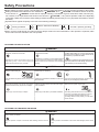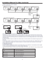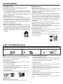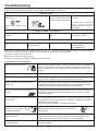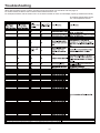
1
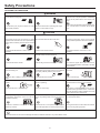
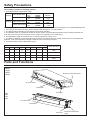
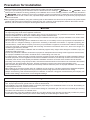
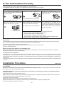
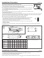
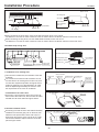
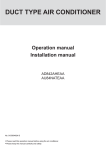
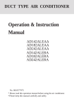
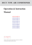
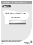
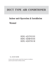
USER'S MANUAL
LSP Duct Inverter R410a 50/60HZ
YH3(D)MXH009BARX-G(P)X
Read this manual before installation and operation
Make sure that it is well kept for later reference
0150512346
Cautions
Safety Precautions
Parts and Functions
Operation
Installation Manual For
Wire Controller
Heating Mode
Care and Maintenance
Troubleshooting
Precauton for Installation
Is The Unit Installed Correctly
Installation Procedure
3
4
6
9
13
14
14
15
17
18
19
English
Contents
EUROPEAN REGULATIONS
CONFORMITY FOR THE MODELS
CE
All the products are in conformity with the following
European provision:
-Low voltage Directive 73/23/EEC
-Low voltage Directive 2006/95/EC
-Electomagnetic CompatibilitY 89/336/EEC
-Electomagnetic CompatibilitY 2004/108/EC
IMPORTANT INFORMATION REGARDING THE REFRIGERANT USED
Contains fluorinated greenhouse gases
covered by the Kyoto Protocol
ROHS
The products are fulfilled with the requirements in the
directive 2002/95/EEC of the European parliament and of
council on the Restriction of the use of Certain Hazardous
Substances in Electrical and Electronic Equipment(EU
RoHS Directive)
This product contains fluorinated greenhouse gases covered
by the Kyoto Protocol.Do not vent into the atmosphere.
Refrigerant type:R410A
GWP*value:1975
GWP=global warming potential
Please fill in with indelible ink,
WEEE
1
the factory refrigerant charge of the product
In accordance with the directive 2002/96/CE of the European
2
the additional refrigerant amount charged in the field
parliament,herewith we inform the consumer about the disand
posal requirements of the electrical and electronic products.
1+2 the total refrigerant charge
on the refrigerant charge label supplied with the product.
DISPOSAL REQUIREMENTS:
The filled out label muset be adhered in the proximity of the
Your air conditioning product is marked with this
product charging port(e.g.onto the inside of the stop value
symbol.This means that electrical and electronic
cover).
products shall not be mixed with unsorted
A contains fluorinated greenhouse gases covered by the
household waste.Do not try to dismantle the
Kyoto Protocol
system yourself:the dismantling of the air
B fatory refrigerant charge of the product:see unit name
conditioning system,treatment of the refrigerant,of oil and of
plate
other part must be done by a qualified installer in accordance C additional refrigerant amount charged in the field
with relevant local and national legislation.Air conditioners
D total refrigerant charge
must be treated at a specialized treatment facility for reuse,
E outdoor unit
recycling and recovery.By ensuring this product is disposed
F refrigerant cylinder and manifold for charging
of correctly,you will help to prevent potential negative consequences for the environment and humen health.Please
contact the installer or local authority for more information.
Battery must be removed from the remote controller and disposed of separately in accordance with relevant local and
nationl legislation.
Cautions
Disposal of the old air conditioner
Before disposing an old air conditioner that goes out of use, please make sure it's inoperative and safe. Unplug the air conditioner
in order to avoid the risk of child entrapment.
It must be noticed that air conditioner system contains refrigerants, which require specialized waste disposal. The valuable
materials contained in an air conditioner can be recycled. Contact your local waste disposal center for proper disposal of an old
air conditioner and contact your local authority or your dealer if you have any question. Please ensure that the pipework of your
air conditioner does not get damaged prior to being picked up by the relevant waste disposal center, and contribute to environmental
awareness by insisting on an appropriate, anti-pollution method of disposal.
Disposal of the packaging of your new air conditioner
All the packaging materials employed in the package of your new air conditioner may be disposed without any danger to the
environment.
The cardboard box may be broken or cut into smaller pieces and given to a waste paper disposal service. The wrapping bag
made of polyethylene and the polyethylene foam pads contain no fluorochloric hydrocarbon.
All these valuable materials may be taken to a waste collecting center and used again after adequate recycling.
Consult your local authorities for the name and address of the waste materials collecting centers and waste paper disposal
services nearest to your house.
Safety Instructions and Warnings
Before starting the air conditioner, read the information given in the User's Guide carefully. The User's Guide contains very
important observations relating to the assembly, operation and maintenance of the air conditioner.
The manufacturer does not accept responsibility for any damages that may arise due to non-observation of the following
instruction.
Damaged air conditioners are not to be put into operation. In case of doubt, consult your supplier.
Use of the air conditioner is to be carried out in strict compliance with the relative instructions set forth in the User's Guide.
Installation shall be done by professional people, don't install unit by yourself.
For the purpose of safety, the air conditioner must be properly grounded in accordance with specifications.
Always remember to unplug the air conditioner before opening inlet grill. Never unplug your air conditioner by pulling on the
power cord. Always grip plug firmly and pull straight out from the outlet.
All electrical repairs must be carried out by qualified electricians. Inadequate repairs may result in a major source of danger for
the user of the air conditioner.
Do not damage any parts of the air conditioner that carry refrigerant by piercing or perforating the air conditioner's tubes with
sharp or pointed items, crushing or twisting any tubes, or scraping the coatings off the surfaces. If the refrigerant spurts out
and gets into eyes, it may result in serious eye injuries.
Do not obstruct or cover the ventilation grille of the air conditioner. Do not put fingers or any other things into the inlet/outlet
and swing louver.
Do not allow children to play with the air conditioner. In no case should children be allowed to sit on the outdoor unit.
3
Safety Precautions
Before starting to use the system, read carefully this "SAFETY PRECAUTIONS" to ensure a proper operation of the system.
Safety precautions described here are classified to "
WARNING" and "
CAUTION". Precautions which are shown
in the column of "
WANING" means that an improper handing could lead to a grave result like a death, serious injury,
etc. However, even if precautions are shown in the column of " CAUTION", a very serious problem could occur depending
on situation. Make sure to observe these safety precautions faithfully because they are very important information to ensure
the safety.
Symbols which appear frequently in the text have following meanings.
Observe instructions faithfully.
Strictly prohibited.
Provide a positive grounding.
When you have read through the manual, keep it always at hand for read consultation. If the operator is replaced, make
sure to hand over this manual to the new operator.
CAUTIONS FOR INSTALLATION
WARNING
The system should be applied to places as office, The system should be installed by your dealer or When you need some optional devices such as a
restaurant, residence and the like.
a professional installer.
humidifier, electric heater, etc., be sure to use the products
which are recommended by us. These devices should
be attached by a professional installer.
Application to inferior environment such as an
engineering shop, could cause equipment
malfunction and serious injury or death.
Installation by yourself is not encouraged because
it could cause such problems as water leakage, Installation by yourself is not encouraged because it could
electrical shock or fire accident by some improper cause such problems as water leakage, electrical shock
handing.
or fire accident by some improper handing.
CAUTION
Do not install nearby the place where may have Depending on the place of installation, a circuit
leakage of flammable gas.
breaker may be necessary.
Drain pipe should be arranged to provide a positive
draining.
ON
OFF
If the gas leakes and gathers around, it may cause
the fire.
Unless the circuit breaker is installed, it could cause
elecrical shocks.
If the pipe is arranged improperly, furniture or the
likes may be damaged by leaked water.
Where strong winds may prevail, the system
should be fixed securely to prevent a collapse.
Install on the place where can endure the weight
of air conditioner.
Make sure the system is grounded.
Bodily injury could result by a collapse.
Bodily injury could result by a careless installation.
Grounding cable should never be connected to
a gas pipe, city water pipe, lightning conductor
rod or grounding cable of telephone. If the
grounding cable is not set properly, it could cause
electric shocks.
CAUTIONS FOR TRANSFER OR REPAIR
WARNING
Modification of the system is strictly prohibited. When the system needs a
repair, consult your dealer.
When the air conditioner is relocated, contact your dealer or a professional
installer.
Improper practice of repair could cause water leakage, electric shock or
fire.
Improper practice of installation could cause water leakage, electric shock
or fire.
4
Safety Precautions
CAUTIONS FOR OPERATION
WARNING
You should refrain from exposing your body directly
to cool wind for a long time.
Do not poke the air inlet or outlet with a bar, etc.
It could affect your physical condition or cause Since the internal fan is operating with a high
some health problems.
speed, it could cause an injury.
When any abnormal condition (scorching smell or
others) is found, stop the operation immediately
and turn off the power switch. Then consult your
dealer.
If you continue the operation without removing the
cause, it could result in a trouble, electric shock
or fire.
CAUTION
The system should never be used for any other Do not handle switches with a wet hand.
purposes than intended such as for preservation
of food, flora and fauna, precision devices or work
of art.
Combustion apparatus should not be placed
allowing a direct exposure to wind of air conditioner.
It could cause deterioration of food or other
problems.
It could cause electric shocks.
Incomplete combustion could occur on the
apparatus.
Do not wash the air conditioner with water.
Do not install the system where the air outlet
reaches directly the flora and fauna.
Make sure to use a fuse of proper electric rating.
It could cause electric shocks.
It will not be good for their health.
Use of steel or copper wire in place of a fuse is
strictly prohibited because it could result in a trouble
or fire accident.
Neither stand on the air conditioner nor
place something on it.
It is strictly prohibited to place a container of
Do not operate the system while the air outlet grill
combustible gas or liquid near the air conditioner is removed.
or to spray it directly with the gas or liquid.
There are risks of falling or injury by collapsed
object.
It could cause a fire accident.
There is a risk of injury.
Do not use the power switch to turn on or off the
system.
Do not touch the air outlet section while the swing
louver is operating.
Do not use such equipment as a water heater, etc.
around the indoor unit or the wire controller.
It could cause a fire or water leakage.
There is a risk of injury.
If the system is operated at the vicinity of such
equipment which generates steam, condensed
water may drip during cooling operation or it could
cause a fault current or short-circuit.
When operating the system simultaneously with
a combustion apparatus, indoor air must be
ventilated frequently.
Check occasionally the support structure of the
unit for any damage after a use of long period of
time.
When cleaning the system, stop the operation and
turn off the power switch.
ON
OFF
Insufficient ventilation could cause an oxygen If the structure is not repaired immediately, the Cleaning should never be done while the internal
deficiency accident.
unit could topple down to cause a personal injury. fans are running with high speed.
Do not put water containers on the unit such as a flower vase, etc.
If the water enters into the unit and damages the electric insulation material, it may cause electric shock.
5
Safety Precautions
The machine is adaptive in following situation
1. Applicable ambient temperature range:
max.
min.
Cooling
max.
Outdoor temperature
min.
max.
Heating Indoor temperature
min.
max.
Outdoor temperature
min.
DB/WB
DB/WB
DB/WB
DB/WB
DB/WB
DB/WB
DB/WB
DB/WB
Indoor temperature
32/23 C
18/14 C
46/24 C
18 C
27 C
15 C
24/18 C
-15 C
2. If the supply cord is damaged, it must be replaced by the manufacturer or its service agent or a similar qualified person.
3. If the fuse on PC board is broken please change it with the type of T 3.15A /250VAC.
4. The wiring method should be in line with the local wiring standard.
5. The breaker of the air conditioner should be all-pole switch, and the distance between its two contacts should be no
less than 3mm. Such means for disconnection must be incorporation in the fixed wiring.
6. The installation height of the indoor unit is recommended from 2.5m to 2.7m.
7. The distance between its two terminal blocks of indoor unit and outdoor unit should not be over 5m. If exceeded, the
diameter of the wire should be enlarged according to the local wiring standard.
8. The waste battery shall be disposed properly.
SW01
Static pressure
[1]
[2]
[3]
[4]
[5]
[6]
[7]
[8]
--
--
--
0
0
--
--
--
0Pa
--
--
--
0
1
--
--
--
10Pa
--
--
--
1
0
--
--
--
20Pa
--
--
--
1
1
--
--
--
30Pa
Parts and Functions
09K(D)
12K(D)
18K(D)
24K(D)
Electrical components Case
Air outlet frame
Evaporator
Drain pan
09K
12K
18K
24K
Air outlet frame
Evaporator
Drain pan
6
Electrical components
Case
Parts and Functions
Buttons of the wire controller
Fan speed switch
Change wind speed
Mode switch
Choose running mode
Swing switch
Open and close air flap
Health switch
Used to control oxygen
function and negative ion
TEMP switch
Used for changing set temperature
MODE
MODE
AUTO
FAN ONLY
COOL
DRY
FAN
AUTO
HIGH
MED
LOW
CENTRAL
OPERATION
STANDBY
PRE-HEAT
DEFROST
HEAT
FIX
FILTER
HEALTH
CHECK
SWING
UNIT NO.
DEMAND
TES
CEN. ADD.
SYS. ADD.
C
F
FAN
SWING
HEALTH
TEMP
CLOCK
TIME
Time switch
It is used to regulate setting time.
MANUAL
ROOM TEMP.
SET TEMP.
TIMER
SET
RECOVERY
TIMER CLOCK UP DOWN VENTILATION
ON
AUTO
OFF
RECOVERY
DAILY
NORMAL
CHECK
ON/OFF
FILTER
RESET
Clock, timing and address setting
Air change switch
It is used to open and close air
change function. The mode is as
follows:
No display-air change (automatic)air change (RECOVERY)-air
change (NORMAL)
Timing switch
It is used for choosing
timing running
Self-inspection
switch
It is used for inspection
service
ON/OFF switch
Do on and off function. The unit is
on when pressing it; and is off
when pressing it again.
Filter reset
After cleaning air inlet
and filter, press
this switch. The unit
begins to run
Reset key
When in abnormal state, push the
reset key with a spike, which may
return the unit to normal
7
Parts and Functions
Display of the wire controller
Centralized display
When controlled by centralized
controller, and chosen by "centralize or
lock" mode, this information is shown.
Air volume display
Display the setting speed
Running display
When the compressor runs, it displays.
Standby display
When the unit is on power and in
"abnormity mode", or outdoor unit
malfunction show alarm , "standby" is
shown to reflect no need to unit.
Running mode display
Show the selected mode
Health function display
Unit number display
Centralized adress
display
System adress display
MODE
MODE
FAN
CENTRAL
AUTO
FAN ONLY
COOL
AUTO
HIGH
MED
OPERATION
STANDBY
PRE-HEAT
DRY
LOW
DEFROST
HEAT
FIX
FILTER
TES
HEALTH
CHECK
UNIT NO.
DEMAND
CEN. ADD.
C
F
SYS. ADD.
Temperature
display
Display the room
temperature, setting
temperature, and
unit number
TIMER
SWING
FAN
SWING
HEALTH
TEMP
CLOCK
TIME
When in preheating
status, "preheating" is
shown.
"Defrost" is shown
when defrosting.
MANUAL
ROOM TEMP.
TIMER
SET TEMP.
SET
RECOVERY
CLOCK UP DOWN VENTILATION
ON
AUTO
OFF
RECOVERY
DAILY
NORMAL
CHECK
FILTER
RESET
Filter screen warning
sign
When the sign is
shown, please clean
the filter screen
ON/OFF
Timing operation
display
Show timing operation
content
Air change display
Inspection status display
Wind swing display
Demand display
When forced to run,"DEMAND"
will be displayed , or show HH/LL
in the temperature zone.
Remarks
The models in the manual don't have health, filter reset and Air change function.
8
Operation
ON/OFF operation
2
MODE
MODE
FAN
OPERATION
HIGH
4
The line controller displays the running state in the latest
time (timing and swing state may not be displayed).
5
1. Press "ON/OFF" switch.
The air conditioner starts operating, and the light on the
wired controller is on.
SWING
FAN
HEALTH
TEMP
CLOCK
TIME
COOL
C
ROOM TEMP.
TIMER
SET
3
RECOVERY
FILTER
RESET
1
ON/OFF
2.Choose operation mode.
Press "mode"switch to change to
"AUTO"---"FAN ONLY"---"COOL"---"DRY"---"HEAT".
3.Press "TEMP" switch
Change set temperature:press TEMP or TEMP
time, [SET] will display,and set temperature will
increase/reduce
CLOCK
CHECK
Press ON/OFF switch on line controller directly
6
every
4.Press "FAN SPEED" switch
FAN ONLY Operation:
Press "FAN SPEED" switch to change to
"HIGH"--"MED"--"LOW"--"HIGH"
In AUTO,COOL,DRY,HEAT Operation:
Press "FAN SPEED" switch to change to
"AUTO"--"HIGH"--"MED"--"LOW"--"AUTO"
5.Press "swing" switch on the line controller to
swing the wind screen.
6.Press "ON/OFF"switch, off.
The light on the line controller is off.
Note
Several seconds after the operation of the line controller,
the setting of the unit will change.
Remarks
Avoid pressing "ON/OFF" switch frequently.
Do not press line controller or switches by sharp objects.
The temperature is on the basis of the setting value. The wind temperature may not reach the setting value because of
the outer air conditioner and system protection.
When the wired controller is power on, the screen fully displays it for two seconds. and clock zone "8888"-"888"-"88"-"8"
flicker for 30 seconds. All the switches are invalid at the time.
9
Operation
Present time setting
The timing is based on the real time. Thus, the real time should be regulated in advance.
The clock regulation steps are as follows:
1.Press "CLOCK" switch
MODE
MODE
FAN
SWING
"CLOCK" flickers, and the time displayed is the real time.
FAN
OPERATION
HIGH
TEMP
HEALTH
2.Press "
C
ROOM TEMP.
TIME
TIMER
SET
CHECK
FILTER
" to regulate the time.
The time increases a minute each time you press " " switch.
The time decreases a minute each time you press " " switch.
HEAT
CLOCK
" and "
RECOVERY
3.Press "setting" switch. The setting is achieved.
CLOCK UP
RESET
If not in timing, the screen displays the real time.
If in timing, the screen displays the timing time.
If you want to know the real time, go to the first step.
ON/OFF
1
Notes
3
2
Setting of power failure compensation function
When SW1-6 on PCB of wire controller is OFF, it will be in power failure compensation. If the SW1-6 is ON, it has no
compensation function.
When the power is on after blackout, the unit will return to the former state if compensation function is set. Otherwise, it
will stop. When restarting the unit, press "ON/OFF" switch on wired controller.
10
Operation
Timing setting
OFF timing: when a set time has elapsed, the unit stops running.
ON timing: when a set time has elapsed, the unit starts.
MODE
MODE
FAN
SWING
FAN
OPERATION
HIGH
HEALTH
TEMP
CLOCK
TIME
1.Press "TIME" switch.
COOL
C
ROOM TEMP.
TIMER
SET
CHECK
FILTER
The display changes with the following sequence:
on
on
no display
CYCLE
ON
OFF
OFF
OFF
RECOVERY
TIMER
ON
RESET
ON/OFF
1
3
Press "ON/OFF" switch
firstly, and set up operation
mode.
Please regulate the clock in
advance before using the
timing function.
2
2.Set up "TIMER"
When timing ON or timing OFF flickers, press " " or " " to
regulate the time
Press" "or " "set up ON/OFF time.
The setting time increases ten minutes each time you press " "
switch.
The setting time decreases ten minutes each time you press " "
switch.
When setting timing ON and timing OFF at the same time,
press "timing" switch to change the setting item.
3.Time setting is achieved. Press"setting"switch.
Cancel timing
If you want to change the timing mode to normal operation,
press "timing" until there is no timing display. When the
timing is invalid, the mode is in normal operation.
parts of wired controller explanation :
1.The unit starts or stops at the setting time. Meanwhile, it displays the timing time.
2."ON Timing, OFF timing and circulation"means that the unit is on and off at the setting time everyday.
Notes
The shorter setting time will be carried out firstly.
If the ON timing and OFF timing are the same, the setting is invalid.
Even in timing condition, you may start or close the unit through pressing "ON/OFF" switch.
11
Operation
Query indoor malfunction history:
In the state of power on or power off, press [CHECK] button, enter the malfunction-querying mode of all indoor units in
the group. Then [CHECK] and [UNIT NO.] will display, and the actual indoor numbers will be displayed in some sequence
(unit number is in decimals). At the same time, in the time region, there will be the current malfunction and the latest time
malfunction, the displaying format is [XX:YY], in which XX stands for the current malfunction, if normal, it will display "--";
YY stands for the latest time malfunction. The failure code of every unit will display for 3 seconds. After the failure codes
of all indoor units in the whole group are displayed, the mode will quit automatically.
How to change the function switches?
No.
Type
Select the master or
the slave controller
State of switch
ON
Function description
set as the slave controller
OFF
set as the master controller
SW1-2
Select the controller
mode
ON
standard controller
OFF
air handler controller
SW1-3
Room temperature
display option
ON
visible room temperature
invisible room temperature
SW1-4
26 lock
OFF
ON
Unavailable 26 lock
SW1-5
Temperature sensor
position option
OFF
ON
available 26 lock
Sensor of the controller
SW1-1
o
o
o
OFF
Sensor in the unit
unavailable
available
SW1-6
Auto restart
ON
OFF
SW1-7
Factory Seting
ON
default setting
SW1-8
Factory Setting
OFF
default setting
1. Switches or jumper wire must be adjusted when the wire controller is powered off. If the wire controller is
powered on, the above operations will be invalid.
2. Function difference between master wire controller and slave one:
Notes
Contrastive
items
Master wire
controller
Slave wire controller
Function
All of functions
Only with below functions: ON/OFF, MODE, FAN
SPEED, SET TEMP., SWING
Installation Manual For Wire Controller
1. Take down wire controller from the holder
FAN
AUTO
HIGH
MED
LOW
CENTRAL
OPERATION
STANDBY
PRE-HEAT
DEFROST
HEAT
FIX
FILTER
TES
CHECK
DEMAND
SYS. ADD.
SWING
C
F
SWING
Wire controller
TEMP
HEALTH
TIME
CLOCK
MANUAL
ROOM TEMP.
SET TEMP.
TIMER
SET
CHECK
FILTER
RECOVERY
TIMER CLOCK UP DOWN VENTILATION
ON
AUTO
OFF
RECOVERY
DAILY
NORMAL
ON/OFF
Bracket
RESET
Screw holes
10.45
HEALTH
UNIT NO.
CEN. ADD.
FAN
5.3
MODE
MODE
AUTO
FAN ONLY
COOL
DRY
2. Install the controller holder
According to the position of 2 screw holes on the
holder, drill 2 holes on the wall, and strike the wood
stopper to the holes respectively.
Then align the 2 screw holes of wired controller
holder to the wood stopper, fix the holder on the wall
with wood screw.
Note:Try a wall as flat as possible for installation.
Don't use excessive force to tighten screws,
otherwise, the holder will be damaged.
3.Wiring instruction
Use shielded wire between indoor and wire controller.And be earthed on one side, or the unit will not work normally
because of interference.
Note:Confirm the terminal connection firmly, and do not get in tough with shielded wire.
4.Place wire controller on the holder, and pay attention not to pressing any wires.
12
Installation Manual For Wire Controller
5. Wiring connections of wire controller:
A
TYPE 1, FOR 09K 12K 18K 24K
Indoor 2
Indoor 1
Indoor N
Wire controller
port A B C
Wire controller
port
A BC
Indoor 15
Wire controller
port
ABC
Indoor 16
Wire controller
port
A BC
(master unit)
Wire controller
port
A BC
Control wiring
of wire
controller
A BC
Wire controller
TYPE 2, FOR 09K(D) 12K(D) 18K(D) 24K(D)
Indoor 1
Indoor 2
Wire controller
port
A BC
B
Indoor N
Wire controller
port
Wire controller
Polar wire A B C
Wire controller
port
ABC
C
Indoor 1
Indoor 15
Indoor 16
Wire controller
port
ABC
A BC
(master unit)
Wire controller
port
A BC
Indoor 1
Wire controller
Polar wire A B C
Polar wire
ABC
ABC
ABC
Wire controller
Wire controller
Wire controller
Control wiring
of wire
controller
A BC
Wire controller
There are three methods to connection wire controller and the indoor units:
A.One wired controller can control max. up to 16 sets of indoor units, and 3 pieces of polar wire must connect the wire
controller and the master unit (the indoor unit connected with wire controller directly), the others connect with the master
unit through 2 pieces of polar wire(3 pieces for model 09K,12K,18K,24K, and the bridge CN22 CN23 on slave units PCB
should be cut off).
B. One wire controller controls one indoor unit, and the indoor unit connects with the wire controller through 3 pieces of
polar wire.
C. Two wired controllers control one indoor unit. The wire controller connected with indoor unit is called master one, the
other is called slave one. Master wire controller and indoor unit; master and slave wire controllers are all connected
through 3 pieces of polar wire.
6. Communication wiring:
The wire controller is equipped with special communication wiring in the accessories. 3-core terminal (1-white 2-yellow
3-red) is connected with the terminal A, B, C of wire controller respectively.
The communication wiring is 5 meter long; if the actual length is more than it, please distribute wiring according to below
table:
Communication wiring length(m)
Dimensions of wiring
< 100
0.3mm2x3-core shielded wire
100 and <200
0.5mm2x3-core shielded wire
200 and <300
0.75mm2x3-core shielded wire
300 and <400
1.25mm2x3-core shielded wire
400 and <600
2mm2x3-core shielded wire
*One side of the shielded sheet of communication wire must be earthed.
13
Heating Mode
"HOT KEEP" function
"HOT KEEP" is operated in the following cases.
When heating is started:
In order to prevent blowing out of cool wind, the indoor unit
fan stopped according to the room temperature which
heating operation is started. Wait for approx. 2 to 3 minute,
and the operation will be automatically changed to the
ordinary heating mode.
Defrosting operation (in the heating mode):
When it is liable to frost, the heating operation is stopped
automatically for 5 to 12 minutes once per approx. one
hour, and defrosting is operated. After defrosting is
completed, operation mode is automatically changed to
ordinary heating operation.
When the room thermostat is actuated:
When room temperature increases and room temperature
controller actuates, the fan speed is automatically changed
to stop under low temperature condition of indoor heat
exchanger. When room temperature decreases, air
conditioner automatically changes over to ordinary heating
operation.
Warming operation
Heat pump type warming
With the heat pump type warming, the mechanism of heat
pump that concentrate heat of outdoor air with the help of
refrigerant to warm the indoor space, is utilized.
Defrosting operation
When a room is warmed with a heat pump type air conditioner,
frost accumulates on the heat exchanger of outdoor unit along
with the drop of indoor temperature. Since the accumulated
frost reduces the effect of warming, it is necessery to
automatically switch the operation to the defrosting mode.
During the defrosting operation, heating operation is
interrupted.
Atmospheric temperature and warming capacity
Warming capacity of heat pump type air conditioner decreases
along with the drop of outdoor temperature.
When the warming capacity is not sufficient, it is recommended
to use another heating implement.
Period of warm-up
Since the heat pump type air conditioner employs a method
to circulate warm winds to warm
the entire space of a room, it takes time before the room
temperature rises.
It is recommendable to start the operation a little earlier in a
very cold morning.
Care and Maintenance
Points to observe
Turn off the power supply switch.
Do not touch with wet hand.
Do not use hot water or volatile liquid.
Thinner
ON
Benzine
Tooth powder
OFF
CAUTION
Care and Cleaning of the unit
Do not open the inlet grill until fan stops completely.
Fan will continue rotating for a while by the law of inertia
after operation is being stopped.
Clean with soft and dry cloth.
If it is very dirty, dissolve neutral detergent in the lukewarm
water and make the cloth wet with the water. After wiping,
clean off the detergent using clean water.
Cleaning the air filter
1.Clean the air filter by lightly tapping it or with the cleaner.
It is more effective to clean
the air filter with water.
If the air filter is very dirty, dissolve neutral detergent in
o
the lukewarm water (approx. 30 C),
rinse the air filter in the water, and thoroughly wash off
the detergent on the air filter
in the plain water.
2.After drying the air filter, set it up on the air conditioner.
Post-Season Care
Operate the unit with FAN mode on a fair day for about half
a day to dry the inside of the unit well.
Stop operation and turn off the power supply switch. Electric
power is consumed even if the air conditioner is in stop.
Clean the air filter and set it in the place.
Pre-Season Care
See that there are no obstacles blocking the air inlet and
air outlet of both indoor and outdoor units.
Make sure that the air filter is not dirty.
Turn on the power supply switch 12 hours before starting
run.
CAUTION
Do not dry the air filter with fire.
Do not run the air conditioner without the air filter.
Do not
use!
14
Troubleshooting
Please check the following things about your air conditioner before making a service call.
Unit fails to start
Is the power source switch
adjust cut in?
Is city supply power in normal? Isn't the signal receiving Isn't the earth leakage breaker
section exposed to the direct in action?
sunlight or strong illumination?
ON
It is dangerous. Turn off the
power supply switch
immediately and contact the
sales dealer.
Power
stoppage?
OFF
Power supply switch is not
ON.
Cooling or heating is not sufficient
Is the thermostat adjusted as
required?
Isn't the air filter dirty?
Isn't any doors or windows left Doesn't any obstacle exist at
open?
the air inlet or outlet?
Cooling is not sufficient
Isn't sun-shine invading direct?
Isn't any unexpected heating
load generated?
Isn't the room much crowded? The wind does not blow during
heating operation.
Isn't it warming up?
When the air conditioner does not operate properly after you have checked the above mentioned items or when the following
phenomenon is observed, stop the operation of the air conditioner and contact your sales dealer.
The fuse or breaker often shuts down.
Water drops off during cooling operation.
There is an irregularity in operation or abnormal sound is audible.
The followings are not malfunction
Water flowing sound is heard.
Sh
Sh uru
ur
u
When the air conditioner is started, when the compressor starts or stops during
operation or when the air conditioner is stopped, it sometimes sounds "shuru
shuru" or "gobo gobo". It is the flowing sound of the refrigerant, and it is not a
trouble.
Cracking sound is heard.
This is caused by heat expansion or contraction of plastics.
It smells.
Air which blows out from the indoor unit sometimes smells. The smell results
from residents of tobacco smoke or cosmetics stuck inside of unit.
During operation, white fog comes out of
indoor unit.
When the air conditioner is used at restaurant etc. where dense edible oil fume
is always exists, white fog sometimes blows out of air outlet during operation.
In this case consult sales dealer for cleaning the heat exchanger.
It is switched into the FAN mode during
cooling.
To prevent frost from being accumulated on the indoor unit heat exchanger, it
is sometimes automatically switched to the FAN mode but it will soon return
to the cooling mode.
The air conditioner can not be restarted soon
after it stops.
Even if the operation switch is turned on, cooling, dehumidifying or heating is
not operable for three minutes after the conditioner is stopped. Because the
protecting circuit is activated.
(During this time air conditioner operates in fan mode.)
Air does not blow or the fan
speed can not be changed
during dehumidifying
When it is excessively cooled during dehumidifying,
the blower automatically repeats reducing and lowering
the fan speed.
Unit does
not start
Wait for
three
minutes
During operation, operation mode has changed
over automatically.
Isn't the AUTO mode selected?
In the case of AUTO mode, operation mode is changed automatically from
cooling to heating or vise-versa according to the room temperature.
Water or steam generates from the outdoor
unit during heating.
This results when frost accumulated on the outdoor unit is removed (during
defrosting operation).
15
Troubleshooting
When failure happens,the fan of indoor unit stop running.The method of check failure code see page 12.
For outdoor failure,the failure code is outdoor failure LED flash times + 20.
For example,the failure code of outdoor unit is 2. the wired controller of indoor unit will display 16(using hexadecimal method).
Ta: ambient temperature sensor
Tm: coil temperature sensor
16
Precaution for Installation
Please read these "Safety Precautions" first and then accurately execute the installation work.
Though the precautionary points indicated herein are divided under two headings,
WARNING and
CAUTION , those
points which are related to the strong possibility of an installation done in error resulting in death or serious injury are listed in
the WARNING section. However, there is also a possibility of serious consequences in relationship to the points listed in the
CAUTION section as well. In either case, important safety related information is indicated, so by all means, properly observe
all that is mentioned.
After completing the installation, along with confirming that no abnormalities were seen from the operation tests, please explain
operating methods as well as maintenance methods to the user (customer) of this equipment, based on the owner's manual.
Moreover, ask the customer to keep this sheet together with the owner's manual.
WARNING
This system should be applied to places as office, restaurant, residence and the like. Application to inferior environment such
as engineering shop could cause equipment malfunction.
Please entrust installation to either the company which sold you the equipment or to a professional contractor. Defects from
improper installations can be the cause of water leakage, electric shocks and fires.
Execute the installation accurately, based on following the installation manual. Again, improper installations can result in water
leakage, electric shocks and fires.
When a large air-conditioning system is installed to a small room, it is necessary to have a prior planned countermeasure for
the rare case of a refrigerant leakage, to prevent the exceeding of threshold concentration. In regards to preparing this
countermeasure, consult with the company from which you perchased the equipment, and make the installation accordingly.
In the rare event that a refrigerant leakage and exceeding of threshold concentration does occur, there is the danger of a
resultant oxygen deficiency accident.
For installation, confirm that the installation site can sufficiently support heavy weight. When strength is insufficient, injury can
result from a falling of the unit.
Execute the prescribed installation construction to prepare for earthquakes and the strong winds of typhoons and hurricanes,
etc. Improper installations can result in accidents due to a violent falling over of the unit.
For electrical work, please see that a licensed electrician executes the work while following the safety standards related to
electrical equipment, and local regulations as well as the installation instructions, and that only exclusive use circuits are used.
Insufficient power source circuit capacity and defective installation execution can be the cause of electric shocks and fires.
Accurately connect wiring using the proper cable, and insure that the external force of the cable is not conducted to the terminal
connection part, through properly securing it. Improper connection or securing can result in heat generation or fire.
Take care that wiring does not rise upward, and accurately install the lid/service panel. Its improper installation can also result
in heat generation or fire.
When setting up or moving the location of the air conditioner, do not mix air etc. or anything other than the designated refrigerant
within the refrigeration cycle. Rupture and injury caused by abnormal high pressure can result from such mixing.
Always use accessory parts and authorized parts for installation construction. Using parts not authorized by this company can
result in water leakage, electric shock, fire and refrigerant leakage.
CAUTION
Execute proper grounding. Do not connect the ground wire to a gas pipe, water pipe, lightning rod or a telephone ground
wire. Improper placement of ground wires can result in electric shock.
The installation of an earth leakage breaker is necessary depending on the established location of the unit. Not installing an
earth leakage breaker may result in electric shock.
Do not install the unit where there is a concern about leakage of combustible gas. The rare event of leaked gas collecting
around the unit could result in an outbreak of fire.
For the drain pipe, follow the installation manual to insure that it allows proper drainage and thermally insulate it to prevent
condensation. Inadequate plumbing can result in water leakage and water damage to interior items.
17
Is The Unit Installed Correctly
Confirm the following items for safe and comfortable use of air conditioner.
The installation work is to be burden on the sales dealer, and do not conduct it by yourself.
Installation place
Avoid installing the air conditioner near
the place where possibility of inflammable
gas leakage exists.
Install the unit at well ventilated place.
Explosion (Ignition) may occur.
If some obstacle exist, it may cause
capacity reduction or noise increase.
Select the place so as not to annoy
neighbor with the hot air or noise.
Snow protection work is necessary where
outdoor unit is blocked up by snow.
For details consult your sales dealer.
Install the air conditioner firmly on the
foundation that can fully support the
weight of the unit.
If not, it may cause vibration or noise.
It is advisable not to install the air
conditioner at the following special place.
It may cause malfunction, consult the
sales dealer when you have to install the
unit on such a place.
The place where corrosive gas generates (Hot spring area etc.)
The place where salt breeze blows (Seaside etc.)
The place where dense soot smoke exists
The place where humidity is extraordinarily high
The place where near the machine which radiates the electromagnetic wave
The place where voltage variation is considerably large
Electric work
The electric work must be burden on the authorized engineer with qualification for electric work and grounding work, and the
work must be conducted in accordance with electric equipment technical standard.
The power source for the unit is to be of exclusive use.
An earth leakage breaker should be installed. This is necessary to prevent electric shock.
The unit must be grounded.
When you change your address or the installation place
Special technology is required for removal or reinstallation of air conditioner, consult the sales dealer. Besides, construction
expense is charged for removal or reinstallation.
For inspection and maintenance
The capacity of air conditioner will decrease by contamination of inside of unit when it is used for about three years although
depending upon the circumstances under which it is used, and so in addition to the usual maintenance service, special
inspection/maintenance service is necessary. It is recommended to make a maintenance contract (charged) by consulting your
sales dealer.
In the place with much dust, the condenser is easy to be blocked, which will result in the low cooling efficiency. So please clean
in period.
Installation Procedure
Indoor Unit
CAUTION
Please do not install the unit in places where flammable gases may be leaked. In case that gas is leaked and accumulated
around the unit, it may cause dangers of fire etc.
The indoor unit shall be installed at locations where cold and hot air could evenly circulated. The following locations
should be avoided
Places with rich saline matters (seaside regions).
Places with plenty of gas sulfides (mainly in warm spring areas where the copper tube and braze weld is prone to corrosion).
Locations with much oil (including mechanical oil) and steam.
Locations using organic solvents.
Places where there are machines generating HF electromagnetic waves.
Positions adjacent to door or window in contact with high-humidity external air. (Easy to generate dew).
Locations frequently using special aerosols.
18
Installation Procedure
Indoor Unit
Selecting the mounting position to install the indoor units
Select suitable places where the outlet air can be sent to the entire room, and convenient to lay out
the connection pipe, connection wire and the drainage pipe to outdoor.
The ceiling structure must be strong enough to support the unit weight.
The connecting pipe, drain pipe and connection wire shall be able to go though the building wall
to connect between the indoor and outdoor units.
The connecting pipe between the indoor and outdoor units as well as the drain pipe shall be as
short as possible.
If it is necessary to adjust the filling amount of the refrigerant, please refer to the installation manual
attached with the outdoor unit.
The connecting flange should be provided by the user himself.
The indoor unit has two water outlets one of which is obstructed at the factory (with a rubber cap). Only the outlet not obstructed
(liquid inlet and outlet side) will be generally used during installation. If applicable, both the outlets should be used together.
An access port must be provided during installation of indoor unit for maintenance.
After selecting the unit installation location, proceed the following steps:
1. Drill a hole in the wall and insert the connecting pipe and wire through a PVC wall-through tube
purchased locally. The wall hole shall be with a outward down slope of at least 1/100.
2. Before drilling check that there is no pipe or reinforcing bar just behind the drilling position.
Drilling shall avoid at positions with electric wire or pipe.
3. Mount the unit on a strong and horizontal building roof. If the base is not firm, it will cause noise,
vibration or leakage.
4. Support the unit firmly.
5. Change the form of the connection pipe, connection wire and drain pipe so that they can go through the wall hole easily.
Installation dimension
A
G
D
B
H
I
C
F
B
E
A
09K(D)
12K(D)
18K(D)
24K(D)
C
D
H
I
E
G
09K
12K
18K
24K
F
Unit model
09K(D)
12K(D)
18K(D)
24K(D)
09K
12K
18K
24K
A
B
C
D
E
F
G
H
I
538 483.5 131
610
255
105
418
508
220
1002 483.5 131
1105
255
105
880
970
220
420
892
370
850
185
640
90
760
152
420
1212
370
1170
185
960
90
1080 152
Installation Procedure
Indoor unit dimensions(unit:mm)
Air Duct
Each of the air sending duct and air return duct shall be fixed on the prefabricated panel of the floor by the iron bracket. The
recommended distance between the edge of the air return duct and the wall is over 150mm.
The gradient of the condensate water pipe shall keep over 1%.
The condensate water pipe shall be thermal insulated.
When installing the ceiling Concealed type indoor unit, the air return duct must be designed and installed as figure shown.
19
Installation Procedure
Air Duct
Building roof of installation
Return air box
Air outlet grille
0.5m (use white motor plug)
2.0m (use red motor plug)
A
Air supply
Ceiling
Unit
There should
be no obstacles
within 1m
Return air box
Unit
Return air
Return air
Air supply
Note:
When connecting the short ducts, use the low static terminals, which color is white.
The distance L from the air outlet of the duct to the air outlet of the air conditioner shall be no more than 0.5 m.
When connecting the long ducts, use the middle static terminals, which color is red.
The distance L from the air outlet of the duct to the air outlet of the air conditioner shall be no more than 2.0 m.
The sketch map of long duct
M8 wide expansion bolt
Drain pipe
Air return duct
Air return blind
Air conditioner
M8 suspender screw
Suspending hook
M8 wide lock washer
Air out duct
Transition duct
Tie-in of air
Air distributary distributary
M8 screw nut
1. Installation of air sending duct
This unit uses rounded duct, the diameter of the duct
is 180mm.
The rounded duct needs to add a transition duct to
connect with the air-sending duct of indoor unit, then
connect with respective separator. As Figure shown,
all the fan speed of any of the separator's air outlet
shall be adjusted approximately the same to meet
the requirement for the room air conditioner.
2. Installation of air return duct
Indoor unit
Soft connection
Transition duct Rounded duct
or static box
Air distributary
Air return blind
Air return duct
Indoor unit
Use rivet to connect the air return duct on the air
return inlet of the indoor unit, then connect the other
end with the air return blind as Figure shown.
rivet
3.Thermal insulation of duct
Air-sending duct and air return duct shall be thermally
insulated. First stick the gluey nail on the duct, then
attach the heat preservation cotton with a layer of
tinfoil paper and use the gluey nail cap to fix. Finally
use the tinfoil adhesive tape to seal the connected
part. As Figure shown.
Tie-in of air
distributary
gluey nail heat preservation cotton tinfoil
gluey nail cap
adhesive tape
20
Installation Procedure
Air Duct
Installing the suspension screw
Use M8 or M10 suspension screws (4, prepared in the field) (when the suspension screw height exceeds 0.9m, M10 size is the
only choice). These screws shall be installed as follows with space adapting to air conditioner overall dimensions according to
the original building structures.
Wooden structure
A square wood shall be supported by the beams and
then set the suspension screws.
New concrete slab
To set with embedded parts, foundation bolts etc.
Square wood
Suspension screw
Iron reinforcement
Beam
Foundation bolt
Knife embedded part Guide plate embedded part Pipe suspension foundation bolt
Original concrete slad
Use hole hinge, hole plunger or hole bolt.
Steel reinforcement structure
Use steel angle or new support steel angle directly.
Hanging bolt
Suspension screw
Support steel angle
Hanging of the indoor unit
Fasten the nut on the suspension screw and then hang the suspension screw in the T slot of the suspension part of the unit.
Aided with a level meter, adjust level of the unit within 5mm
Installation Procedure
Refrigerant Pipe
CAUTION
Pipe size (unit :mm)
In installation, if there is refrigerant gas leakage, please take ventilation
measures immediately. The refrigerant gas will generate poisonous
gas upon contacting fire.
After installation, please verify that there is no refrigerant leakage.
The leaked refrigerant gas will produce poisonous gas when meeting
fire source such as heater and furnace etc.
Model
Pipe material
Phosphorus deoxidized copper seamless pipe (TP2M) for air conditioner.
09K(D)
12K(D)
09K
12K
18K(D)
18K
Gas side
Liquid side
9.52
6.35
12.7
6.35
24K(D)
24K
15.88
9.52
Allowable pipe length and drop
These parameters differ according to the outdoor unit. See the instruction manual attached with the outdoor unit for details.
Supplementary refrigerant
The refrigerant supplementation shall be as specified in the installation instructions attached with the outdoor unit.
The adding procedure shall be aided with a measuring meter for a specified amount of supplemented refrigerant.
Note:
Overfilling or underfilling of refrigerant will cause compressor fault. The amount of the added refrigerant shall be as specified
in the instructions.
Connecting pipe Installing torque
O.D.(mm)
(N-m)
Connection of refrigerant pipe
Conduct flared connection work to connect all refrigerant pipes.
6.35
11.8 (1.2kgf-m)
The connection of indoor unit pipes must use double spanners.
The installing torque shall be as given in the following table.
Wall thicknessof connection pipe 0.8mm
9.52
24.5 (2.5 kgf-m)
12.7
49.0 (5.0 kgf-m)
Double-spanner
operation
15.88
78.4 (8.0 kgf-m)
Creating vacuum
With a vacuum pump, create vacuum from the stop valve of the outdoor unit. Emptying with refrigerant sealed in the outdoor
unit is absolutely forbidden.
21
Installation Procedure
Refrigerant Pipe
Open all valves
Open all the valves on the outdoor unit.
Gas leakage detection
Check with a leakage detector or soap water if there is gas leakage at the pipe connections and bonnets.
Insulation treatment
Conduct insulation treatment on both the gas side and liquid side of pipes respectively.
During cooling operation, both the liquid and gas sides are cold and thus shall be
insulated so as to avoid dew generation.
The insulating material at gas side shall be resistant to a temperature
Indoor unit
above 120 C
The indoor unit pipe connection part shall be insulated.
The notch upward(Attached detail view)
Field piping side
Subsidiary insulation tube
Installation Procedure
Drain Pipe
CAUTION
In order to drain water normally, the drain pipe shall be processed as specified in the installation manual and shall be thermal
insulated to avoid dew generation. Improper hose connection may cause indoor water leakage.
Requirements
1.5m~2m
Support
The indoor drain pipe shall be thermal insulated.
The connection part between the drain pipe and
the indoor unit shall be insulated so as to prevent
Down slope above 1/100
dew generation.
S type elbow
Insulation
(supplied
by the user)
The drain pipe shall be slant downwards (greater
than 1/100). The middle part shall not be of S type
elbow, otherwise abnormal sound will be produced.
To the largest (app. 10cm)
The horizontal length of the drain pipe shall be less than 20 m. In case of
long pipe, supports shall be provided every 1.5 _ 2m to prevent wavy form.
Central piping shall be laid out according to the right figure.
VP30
Take care not to apply external force onto the drain pipe connection part.
Down slope above 1/100
Pipe and insulation material
Pipe
Rigid PVC pipe VP20 mm (internal diameter)
Insulation
Foamed PE with thickness above 7 mm
Wall
Outside
Slant
Drain pipe (supplied
by the user)
Hose
Drain pipe size: (3/4") PVC pipe
The hose is used for adjusting the off-center and angle of the rigid PVC pipe.
Directly stretch the hose to install without making any deformation.
The soft end of the hose must be fastened with a hose clamp.
Please apply the hose on horizontal part Insulation treatment.
Wrap the hose and its clamp up to the indoor unit without any
clearance with insulating material, as shown in the figure.
Hose
Subsidiary insulation
Drain confirmation
During trial run, check that there is no leakage at the pipe connection part during water draining even in winter.
22
Hose clamp
Insulation
Rigid PVC pipe
Installation Procedure
Electrical wiring
WARNING
DANGER OF BODILY INJURY OR DEATH
TURN OFF ELECTRIC POWER AT CIRCUIT BREAKER OR POWER SOURCE BEFORE MAKING ANY ELECTRIC
CONNECTIONS. GROUND CONNECTIONS MUST BE COMPLETED BEFORE MAKING LINE VOLTAGE CONNECTIONS.
Precautions for Electrical wiring
Electrical wiring work should be conducted only by authorized personnel.
Do not connect more than three wires to the terminal block. Always use round type crimped terminal lugs with insulated grip on
the ends of the wires.
Use copper conductor only.
Wiring connection
Make wiring to supply power to the outdoor unit, so that the power for the indoor unit is supplied by terminals.
Indoor unit
terminal block
Outdoor unit
terminal block
23
1
2
3
Y/G
1(N) 2(L) 3(C)
Y/G
2014 johnson Controls, lnc.
www.johnsoncontrols.com
AHDJXHAMX-140301
Johnson Controls reserve the right to change product features without prior notice.