1
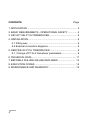
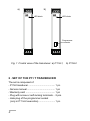
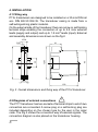
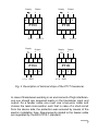
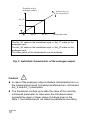
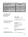
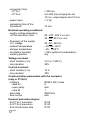
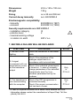
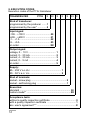
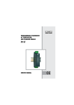
PROGRAMMABLE TRANSDUCER OF D.C. VOLTAGE AND D.C. CURRENT P11H 01 90 A O IS K I F Y T R E C SERVICE MANUAL 1 T CONTENTS Page 1. APPLICATION .......................................................................... 3 2. BASIC REQUIREMENTS - OPERATIONAL SAFETY ............. 4 3. SET OF THE P11H TRANSDUCER ......................................... 5 4. INSTALLATION ......................................................................... 6 4.1 Fitting way ......................................................................... 6 4.2 External connection diagrams ........................................... 6 5. SERVICE OF P11H TRANSDUCER ........................................ 8 5.1. Change of P11H-2 transducer parameters ....................... 8 6. TECHNICAL DATA ................................................................... 11 7. BEFORE A FAILURE WILL BE DECLARED .......................... 13 8. EXECUTION CODES ............................................................. 14 9. MAINTENANCE AND WARRANTY ........................................ 15 2 1. APPLICATION The P11H transducer is destined to the conversion of ± 100 V, ± 600 V d.c. voltage and ± 1 A, ± 5 A d.c. current into into a d.c. current or d.c. voltage standard signal. The output signal is galvanically isolated from the input signal and the supply. The P11H transducer is offered in two basic versions: l P11H-1, with programmed parameters by the producer acc. the ordered execution code. l P11H-2, with programmed parameters by the producer acc. the ordered execution code and with the possibility to change the parameters by the user by means of a computer through the PD11 programmer. The PD11 programmer is a universal device serving to programme all the P11 and P12 series. The PD11 programmer realizes also following functions: - conversion of the measured value into an optional output signal on the base of the individual linear characteristic, - switching on or off the automatic compensation and possibility to introduce a manual correction, - storage of maximal and minimal values. - programming of the measurement averaging time, - blocking of the parameter introduction by means of a password. Using the PD11 programmer, one can read out in any time from the P11H transducer: - the measured value, - the maximal and minimal value, - the signal on the analogue output in percentage of the range. 3 a) b) P11H LED diode P11H LED diode Programmer connector Fig. 1 Frontal view of the transducer: a) P11H-1, 2 . SET OF THE P11 T TRANSDUCER The set is composed of: - P11H transducer ........................................ 1 pc - Service manual .......................................... 1 pc - Warranty card ............................................ 1 pc - Plug with screw or self-locking terminals .. 2 pcs - Hole plug of the programmer socket (only in P11H-2 execution) ........................ 1 pc 4 b) P11H-2 3. BASIC REQUIREMENTS, OPERATIONAL SAFETY Symbols located in this service manual mean: ! - Especially important, one must acquaint with this before connecting the transducer. The non-observance of notices marked by these symbols can occasion the damage of the transducer. ? - One must take note of this when the transducer is working inconsistently to the expectations. In the security scope the transducer meets the requirements of the EN 61010-1 standard. ! Remarks concerning the operator safety: P11T transducers are destined to be mounted on 35 mm DIN rails. In the range of operational safety they are in conformity with the EN 61010-1standard requirements. - The installation and transducer connection should be operated by a qualified personnel. - One must take into consideration all accessible protection requirements. - Before switching the instrument on, one must check the correctness of the network lead connection. - In case of the protection terminal connection with a separate lead one must remember to connect it before the connection of network leads. - Do not connect the instrument to the network through an autotransformer. - Before taking the transducer housing out, one must turn the supply off. - The removal of the transducer housing during the warranty contract period may cause its cancellation. - The programmer connector is destined only for the PD11 programmer connection. After the transducer programming, one should put the hole plug of the programmer connector. 5 4. INSTALLATION 4.1 Fitting way P11H transducers are designed to be installed on a 35 mm DIN rail acc. DIN EN 50 022-35. The transducer casing is made from a self-extinguishing plastic material. On the external side of the transducer there are screw or self-locking terminal strips enabling the connection of up to 2.5 mm2 external leads (supply and output) and up to 1.5 mm2 leads (input). External and assembly dimensions are shown on the fig.2. 15,24 41 93 120,7 35 120 5,08 22,5 100 Fig. 2 Overall dimensions and fixing way of the P11H transducer. 4.2.Diagrams of external connections ! The P11T transducer has two sockets of terminal strips to which two connectors are connected. A screw plug or a self-locking plug are included depending on the chosen type by the user in the order code. The Fig.3 shows the connection way of external signals. The connection diagram is also placed on the transducer housing. 6 Supply 6 7 Output + - 8 9 Supply 6 2 3 Supply 6 7 4 1 ± 100 V GND 2 Output + - 8 9 ± 1 A GND 3 8 9 2 3 Supply 6 7 4 ± 600 V GND P11H 1 - P11H P11H 1 7 Output + Output + - 8 9 P11H 4 1 2 3 4 ± 5 A GND Fig. 3 Description of terminal strips of the P11T transducer. In case of transducers working in an environment of high interferences one should use screened leads on the transducer input and output. As a feeder cable one must use a two-wire cable and choose the lead cross-section such that in case of a short-circuit from the device side, the protection was ensured by means of the electric installation fuse. Requirements related to the feeder cable are regulated by the EN 61010-1 standard. 7 5. SERVICE After connecting external signals and turning on the power supply, the transducer is ready to work. The lighted LED diode indicates only the turn-on of the transducer to the mains and signals the transducer work. The P11H-1 transducer works with programmed parameters according the execution code and there is no possibility to change these parameters. Such a possibility exists in the case of a P11H-2 transducer. To this effect, a PD11 programmer and a computer are necessary. 5.1 Modification way of the P11H-2 parameters The connection way of the P11H-2 transducer to the computer is shown on the Fig. 4. 16 x max 8 x max P11H DB 25 DB 25 DB 9 RS232 RJ 12 adapter DB9 / DB25 Kit of PD11 programmer Fig. 4. Connection way of the P11H-2 transducer with the computer. In case of the PD11 programmer connection to the computer DB9 connector, one should use a DB9/DB25 adapter ( included in PD11 programmer kit). The programmable parameters of the transducer are shown in the table 1. The programming of parameters is possible after the previous introduction of the password 8 Table 1 Output parameters 0...9999.9 s The inscription of 0 causes the turnoff of the measurement and stop the transducer work. Turn-off or on of the individual users linear characteristic (individual characteristic of the analogue output) On - characteristic turned on Off - characteristic turned off When the characteristic is turned off, then the transducer operates with its maximal range depending on the type of input or output. Parameters of the individual characteristic of the analogue output. On the base of given coordinates of two points by the user, the transducer determines ( from the system of equations) the coefficients a and b of the individual characteristic. Anl_Y1 = a . Anl_X1 + b Anl_Y2 = a . Anl_X2 + b Possibility of setting: - 99999.... 99999 N HE W AL LE U IC IB VID ST SS DI RI ON CE IN TE D AC THE RAC RNE A U CH IS T Averaging time of the measurement Where: Anl_X1 and Anl_X2 - measured value AnL_Y1 and Anl_Y2 - expected value on the analogue output. The Fig.5 shows the graphic presentation explaining the idea of the individual characteristic of the analogue output. Service parameters Range of changes 100 V - range: - 100 V... 100 V 600 V - range: - 600 V... 600 V 1 A - range : - 1 A...1 A 5 A - range : - 5 A...5 A Input parameters Parameter description Kind of input signal Manufacturers parameters The manufacturers parameters are shown in the table 2. Introduction of a new password - 99999... 99999 Possibility of setting the curent time. Time format: hh:mm:ss When there is a lack of supply the parameter is not remembered. 00:00:00 ... 23:59:00 9 Quantity on the analogue output Optional slope of the characteristic Anl_Y2 Anl_Y1 Anl_X1 Anl_X2 Measured value The Anl_X1 value on the transducer input => Anl_Y1 value on the analogue input The Anl_X2 value on the transducer input => Anl_Y2 value on the analogue input. The other points of the characteristic can be evaluate. Fig. 5 Individual characteristic of the analogue output Caution! ? l In case of the analogue output individual characteristic turn-on, the measurement result is linearly transformed acc. introduced Anl_X and Anl_Y parameters. l The transducer controls up to date the value of the currently introduced parameter. In case when the introduced value exceeds the upper or lower range of change given in the table 1, the transducer do not make the parameter recording. 10 Manufacturers parameters of the P11H transducer Parameter description Table 2 Standard value Type of input 100 V Averaging time of the measurement 0,1s Characteristic of the analogue output Turn off Anl_X1, Anl_X2 0 Anl_Y1, Anl_Y2 0 Password Current time 0 00:00:00 6. TECHNICAL DATA Basic parameters: - input signals - 100... 100 V - 600... 600 V, input resistance > 3.4 MW - 1... 1 A, - 5... 5 A, input resistance = 20 mW ± 10% - analogue output galvanically isolated with a resolution: 0.01% of the range programmed current 0/4...20 mA load resistance £ 500 W programmed voltage 0...10 V load ³ 500 W - accuracy class - additional error from the ambient temperature change 0.2 the minimal sub-range in P11H-2 is 4 times smaller than the full range ± (0.1% of the range/10 K) 11 - conversion time: - P11H-1 - P11H-2 - power input - preheating time of the transducer < 200 ms min 200 ms (averaging time min 100 ms + output response time 100 ms) < 3 VA 10 min. Nominal operating conditions: - supply voltage depending on the execution code 85...230...253 V a.c./d.c. 20...24...50 V a.c./d.c. - frequency of the supply a.c. voltage 40...50...440 Hz - ambient temperature - 25...23...55°C - storage temperature - 25... + 85°C - air relative humidity < 95% (without condensation) - working position any Voltage overload: - short duration (3 s) - long duration 2 Un (< 1000 V) 20% Current overload: - short duration (3 s) - long duration 10 In 20% Communication parameters with the computer (only in P11H-2): - interface RS232, 8N1 mode - data bit 8 - even parity lack - stop bit 1 - baud rate 9600 bit/s - flow control lack Ensured protection degree: - for P11H-1 execution - for P11H-2 execution - from the terminal side 12 IP 50 IP 40 IP 20 Dimensions 22.5 x 120 x 100 mm Weight 125 g Fixing on a 35 mm DIN rail Current decay immunity acc. EN 50082-2 Electromagnetic compatibility: - immunity EN 50082-2 (1997) - emission EN 50081-2 (1996) Security requirements acc. IEC 61010-1 - installation category III - pollution level 2 - maximal working voltage in relation to earth 600 V a.c. ! 7. BEFORE A FAILURE WILL BE DECLARED SYMPTOMS 1. the LED is not lighting 2. A signal inconsistent with our expectations occurs on the transducer output 3. The transducer is not communicating with the computer PROCEDURE ? NOTES Check the connection of the feeder cable Check if the resistance of the analogue output load is in accordance with technical data. Check if the individual characteristic is turned on. In case of necessity, change parameters of the individual characteristic (see Fig. 5) or introduce parameters set by the producer. Check if the PD11programmer is connected correctly. Check if the proper communication port has been chosen. Only in P11H-2 Only in P11H-2 - In case of a special execution or to obtain more detailed technical information please contact the manufacturers Export Dept. Tel./fax: (48-68) 325 40 91 13 8. EXECUTION CODES Execution codes of the P11H transducer TRANSDSUCER P11H X XX X X X XX X Kind of transducer: programmed by the producer ....... 1 programmed by the user* ............. 2 Input signal: -100... +100 V ..................................... 00 -600... +600 V ..................................... 01 -1... +1 A ............................................. 02 -5... +5 A ............................................. 03 on order .............................................. XX Output signal: voltage, 0... 10 V ......................................... current, 0... 20 mA ...................................... current, 4... 20 mA ...................................... current, 0... 5 mA ........................................ on order ....................................................... 1 2 3 4 9 Supply: 85... 253 V a.c./d.c. ............................................. 1 20... 50 V a.c./ d.c. .............................................. 2 Kind of terminals: socket - screw plug ..................................................... 0 socket - self-locking plug ............................................ 1 Execution: standard ............................................................................ 00 custom-made** ................................................................. XX Acceptance tests: without a quality inspection certificate ...................................... 0 with a quality inspection certificate ........................................... 1 acc. users agreement*** .......................................................... X 14 * The programmable transducer has a universal input. When ordering give the code of the input signal which has to be programmed ** After agreeing by the producer *** The producer will settle the execution code number Coding example: The P11H-1-02-1-1-0-00-0 code means: the execution of a P11H transducer programmed by the producer without the possibility to re-programme it by the user, with an input signal: - 1...1 A, output signal: 0 -10 V, supply voltage: 85...253 V a.c./d.c., with a socketscrew plug, standard execution, without a quality inspection certificate. 9. MAINTENANCE AND WARRANTY The P11H transducer does not require any periodical maintenance. In case of some incorrect unit operations: 1. In the period of 12 months from the date of purchase: One should take the transducer down from the installation and return it to the LUMELs Quality Control Dept. If the unit has been used in compliance with the instructions, LUMEL S.A. warrants to repair it free of charge. 2. After the warranty period: One should turn over the transducer to repair in a certified service workshop. The disassembling of the housing causes the cancellation of the granted warranty. Spare parts are available for the period of ten years from the date of purchase. LUMEL S.A. reserves the right to make changes in design and specifications of any products as engineering advances or necessity requires. 15 SALES PROGRAMME n n n n n n n n n n n n DIGITAL PANEL METERS MEASURING TRANSDUCERS ANALOG PANEL METERS (DIN INSTRUMENTS) ANALOG and DIGITAL PORTABLE METERS INDUSTRIAL and DOMESTIC CONTROLLERS CHART AND PAPERLESS RECORDERS POWER CONTROL UNITS and INVERTERS AUTOMOTIVE INDICATORS CALIBRATORS MEASUREMENT ACCESSORIES MEASURING SYSTEMS ( energy, heat, control ) CUSTOM-MADE PRODUCTS WE ALSO OFFER OUR SERVICES IN THE PRODUCTION OF: n ALUMINIUM ALLOY PRESSURE CASTINGS n PRESSURE CASTING DIES and INJECTION MOULDS n PRECISION ENGINEERING and THERMOPLASTIC PARTS QUALITY PROCEDURES: According ISO 9001 international requirements. For more detailed information please write to or phone our Export Dept November 2002 Lubuskie Zak³ady Aparatów Elektrycznych - LUMEL S.A. ul. Sulechowska 1 65-950 Zielona Góra - Poland Tel. (48-68) 329 51 00 (exchange) Fax: (48-68) 329 51 01 e-mail: [email protected] http://www.lumel.com.pl Export Department: Tel.: (48-68) 329 52 38 Fax: (48-68) 325 40 91 e-mail: [email protected]