1
MTH500
TETRA Portable Radio
R1:380-400 MHz (PT811F)
R2:410-430 MHz (PT511F)
Basic Service Manual
Part Number: 6802963C65
@6802963C65@
Printed on recycled paper. European Publications Department, 6802963C65, Issued: 04.02.
Scope of this Manual
Trademarks
This manual contains information necessary to test and
maintain the MTH500 Portable radio at the module level. It
also contains information on radio assembling and disassembling. Accordingly, information in this manual is divided into four sections:
MOTOROLA and the Stylized M Logo are registered in the
U.S.Patent and Trademark Office. All other product or service
names are the property of their respective owners.
•
Overview
•
Test Setup and Testing
•
Programming the Radio
•
Maintenance
Manual Revisions
Changes which occur after this manual is printed are described in
Manual Revisions. These Manual Revisions provide complete
information on changes including pertinent parts listing data.
© Motorola, Inc. 2001
Safety And General Information
Important Information on Safe and Efficient
Operation
Read this Information before Using your
handset
The information provided in this document supersedes the
general safety information contained in service manuals
published prior to June 2001. For information regarding
handset use in a hazardous atmosphere please refer to the
Factory Mutual (FM) Approval Manual Supplement or
Instruction Card which is included with handset models
that offer this capability.
Radio Frequency (RF) Operational Characteristics
Related Publications
• 68P02963C30-O MTH500 User Guide
• 68P02963C70-O MTH500 Detailed Service Manual
• 68P02956C20-F CPS User’s Guide
• IFR-Operational Manual Supplement 46882-324
Your handset contains a radio frequency transmitter to
convey the information you wish to send as well as
occasional automatic signals used to sustain connection
with the wireless network, and a receiver which enables
you to receive communication and connection information
from the network.
Handset Operation And EME Exposure
• IFR-Operational Manual 46882-274T
Your Motorola handset is designed to comply with the
following national and international standards and
guidelines regarding exposure of human beings to radio
frequency electromagnetic energy:
Computer Software Copyrights
• United States Federal Communications
Commission, Code of Federal Regulations; 47
CFR part 2 sub-part J
• American National Standards Institute (ANSI) /
Institute of Electrical and Electronic Engineers
(IEEE) C95. 1-1992
• Institute of Electrical and Electronic Engineers
(IEEE) C95.1-1999 Edition
• National Council on Radiation Protection and
Measurements (NCRP) of the United States,
Report 86, 1986
• International Commission on Non-Ionizing
Radiation Protection (ICNIRP) 1998
• Ministry of Health (Canada) Safety Code 6.
Limits of Human Exposure to Radiofrequency
Electromagnetic Fields in the Frequency Range
from 3 kHz to 300 GHz, 1999
The Motorola products described in this manual may include
copyrighted Motorola computer programs stored in
semiconductor memories or other media. Laws in the United
States and other countries preserve for Motorola certain exclusive
rights for copyrighted computer programs, including the
exclusive right to copy or reproduce in any form the copyrighted
computer program. Accordingly, any copyrighted Motorola
computer programs contained in the Motorola products described
in this manual may not be copied or reproduced in any manner
without the express written permission of Motorola. Furthermore,
the purchase of Motorola products shall not be deemed to grant
either directly or by implication, estoppel, or otherwise, any
license under the copyrights, patents or patent applications of
Motorola, except for the normal non-exclusive royalty free
license to use that arises by operation of law in the sale of a
product.
ii
• Australian Communications Authority Radiocommunications (Electromagnetic Radiation –
Human Exposure) Standard 1999 (applicable to
wireless phones only)
• Anatel, Brasil Regulatory Authority
“This equipment is in compliance with the limits
of Specific Absorption Rate which refer to the
exposal to electric, magnetic and electromagnetic
fields adopted by ANATEL.”
To assure optimal handset performance and make sure
human exposure to radio frequency electromagnetic
energy is within the guidelines set forth in the above
standards, always adhere to the following procedures:
Phone Operation
When placing or receiving a phone call, hold your handset
as you would a wireline telephone. Speak directly into
the microphone.
Two-way radio Operation
When using your handset, hold the handset in a vertical
position with the microphone 2.5 to 5 cm away from
your mouth.
Body-worn Operation
To maintain compliance with these RF exposure
guidelines, if you wear a handset on your body when
transmitting, always place the handset in a Motorola
approved belt clip or leather case for this product. Use
of non-Motorola-approved accessories may exceed these
RF exposure guidelines. If you do not use a Motorola
approved body-worn accessory and are not using the
handset in the intended use positions along side of the
head in the phone mode or in front of the face in the
two-way radio mode, then ensure the antenna and
handset is kept the following minimum distances from
the body when transmitting:
•
Phone or Two-way radio mode: 2.5 cm
•
Data operation using any data feature with or
without an accessory cable: 2.5 cm
Antenna Care
Use only the supplied or an approved replacement
antenna. Unauthorized antennas, modifications, or
attachments could damage the handset and may violate
FCC regulations.
DO NOT hold the antenna when the radio is “IN
USE”. Holding the antenna affects call quality and may
cause the radio to operate at a higher power level than
needed.
Approved Accessories
For a list of Approved Motorola accessories, please see
“REPLACEMENT PARTS AND KITS” on page 45.
Electromagnetic Interference/Compatibility
NOTE: Nearly every electronic device is susceptible to
electromagnetic interference (EMI) if inadequately
shielded, designed or otherwise configured for
electromagnetic compatibility.
Facilities
To avoid electromagnetic interference and/or
compatibility conflicts, turn off your handset in any
facility where posted notices instruct you to do so.
Hospitals or health care facilities may be using
equipment that is sensitive to external RF energy.
Aircraft
When instructed to do so, turn off your handset when on
board an aircraft. Any use of a handset must be in
accordance with applicable regulations per airline crew
instructions.
Medical Devices
Pacemakers
The Health Industry Manufacturers Association
recommends that a minimum separation of 15
centimetres be maintained between a handheld wireless
handset and a pacemaker. These recommendations are
consistent with those of the U.S Food and Drug
Administration.
Persons with pacemakers should:
• ALWAYS keep the handset more than 15 centimetres from their pacemaker when the handset is
turned ON.
• not carry the handset in the breast pocket.
• use the ear opposite the pacemaker to minimise
the potential for interference.
• turn the handset OFF immediately if you have
any reason to suspect that interference is taking
place.
Hearing Aids
Some digital wireless handsets may interfere with some
hearing aids. In the event of such interference, you may
want to consult your hearing aid manufacturer to discuss
alternatives.
Other Medical Devices
If you use any other personal medical device, consult the
manufacturer of your device to determine if it is
adequately shielded from RF energy. Your physician
may be able to assist you in obtaining this information.
Safety and General
Use While Driving
Check the laws and regulations on the use of radios in the
area where you drive. Always obey them.
When using the handset while driving, please:
• Give full attention to driving and to the road.
iii
• Use hands-free operation, if available.
• Pull off the road and park before making or answering a
call if driving conditions so require.
Operational Warnings
!
WARNING
For Vehicles Equipped with an Air Bag
Do Not place a handset or install a Vehicular Adapter in
the area over an air bag or in the air bag deployment area.
Air bags inflate with great force. If a radio is placed in
the air bag deployment area and the air bag inflates, the
radio may be propelled with great force and cause serious
injury to occupants of the vehicle.
Potentially Explosive Atmospheres
Turn off your handset prior to entering any area with a
potentially explosive atmosphere, unless it is a handset
type especially qualified for use in such areas as
“Intrinsically Safe” (for example, Factory Mutual, CSA,
UL, or CENELEC Approved). Do not remove, install, or
charge batteries in such areas. Sparks in a potentially
explosive atmosphere can cause an explosion or fire
resulting in bodily injury or even death.
NOTE: The areas with potentially explosive atmospheres referred to above include fuelling areas
such as below decks on boats, fuel or chemical
transfer or storage facilities, areas where the air
contains chemicals or particles such as grain,
dust, or metal powders, and any other area
where you would normally be advised to turn
off your vehicle engine. Areas with potentially
explosive atmospheres are often, but not
always, posted.
Blasting Caps and Areas
To avoid possible interference with blasting operations,
turn off your handset when you are near electrical
blasting caps, in a blasting area, or in areas posted: “Turn
off two-way radio.” Obey all signs and instructions.
Operational Cautions
!
Caution
Antennas
Do not use any handset that has a damaged antenna.
If a damaged antenna comes into contact with your skin,
a minor burn can result.
iv
Batteries
All batteries can cause property damage and/or bodily
injury such as burns if a conductive material such as
jewellery, keys, or beaded chains touch exposed terminals.
The conductive material may complete an electrical circuit
(short circuit) and become quite hot. Exercise care in
handling any charged battery, particularly when placing it
inside a pocket, purse, or other container with metal
objects.
European Union Directives Conformance
Statement
This product is in conformance with the TETRA
(TErrestrial Trunked RAdio) standard.
This product is in conformance with the requirements of
the applicable EU Council Directives.
Declarations of Conformance with the requirements are
located at:
Motorola a/s
Midtager 20
DK-2605 Brondby
MTH500 Portable Radio Basic Service Manual
CONTENTS
Scope of this Manual . . . . . . . . . . . . . . . . . . . . . . . . . . . . . . . . . . . . . . . . . . . . . . ii
Manual Revision . . . . . . . . . . . . . . . . . . . . . . . . . . . . . . . . . . . . . . . . . . . . . . . . . ii
Related Publications . . . . . . . . . . . . . . . . . . . . . . . . . . . . . . . . . . . . . . . . . . . . . . . ii
Computer Software Copyrights . . . . . . . . . . . . . . . . . . . . . . . . . . . . . . . . . . . . . . ii
Trademarks . . . . . . . . . . . . . . . . . . . . . . . . . . . . . . . . . . . . . . . . . . . . . . . . . . . . . . ii
Safety and General Information . . . . . . . . . . . . . . . . . . . . . . . . . . . . . . . . . . . . . . ii
Radio Frequency (RF) Operational Characteristics . . . . . . . . . . . . . . . . . . . . . . ii
Handset Operation and EME Exposure . . . . . . . . . . . . . . . . . . . . . . . . . . . . . . . ii
Electromagnetic Interference/Compatibility . . . . . . . . . . . . . . . . . . . . . . . . . . . iii
Facilities . . . . . . . . . . . . . . . . . . . . . . . . . . . . . . . . . . . . . . . . . . . . . . . . . . . . . . iii
Aircraft . . . . . . . . . . . . . . . . . . . . . . . . . . . . . . . . . . . . . . . . . . . . . . . . . . . . . . . iii
Medical Devices . . . . . . . . . . . . . . . . . . . . . . . . . . . . . . . . . . . . . . . . . . . . . . iii
Safety and General . . . . . . . . . . . . . . . . . . . . . . . . . . . . . . . . . . . . . . . . . . . . iii
Operational Warnings . . . . . . . . . . . . . . . . . . . . . . . . . . . . . . . . . . . . . . . . . . . . . .iv
For Vehicles Equipped with an Air Bag . . . . . . . . . . . . . . . . . . . . . . . . . . . . .iv
Potentially Explosive Atmospheres . . . . . . . . . . . . . . . . . . . . . . . . . . . . . . . .iv
Blasting Caps and Areas . . . . . . . . . . . . . . . . . . . . . . . . . . . . . . . . . . . . . . . . .iv
Antennas . . . . . . . . . . . . . . . . . . . . . . . . . . . . . . . . . . . . . . . . . . . . . . . . . . . . .iv
Batteries . . . . . . . . . . . . . . . . . . . . . . . . . . . . . . . . . . . . . . . . . . . . . . . . . . . . . .iv
European Union Directives Conformance Statement . . . . . . . . . . . . . . . . . . . . .iv
MTH500 Portable Radio Model Information
MTH500 Model Specifications
CHAPTER 1
OVERVIEW
. . . . . . . . . . . . . . . . .ix
...............................x
..................................................1
Digital Modulation Technology . . . . . . . . . . . . . . . . . . . . . . . . . . . . . . . . . . . . . . 1
Voice Compression Technology . . . . . . . . . . . . . . . . . . . . . . . . . . . . . . . . . . . . . . 2
Description . . . . . . . . . . . . . . . . . . . . . . . . . . . . . . . . . . . . . . . . . . . . . . . . . . . . . 2
Transceiver Description . . . . . . . . . . . . . . . . . . . . . . . . . . . . . . . . . . . . . . . . . 2
Digital Section Description . . . . . . . . . . . . . . . . . . . . . . . . . . . . . . . . . . . . . . . 2
Transmitter Path Description . . . . . . . . . . . . . . . . . . . . . . . . . . . . . . . . . . . . . . 3
Receiver Path Description . . . . . . . . . . . . . . . . . . . . . . . . . . . . . . . . . . . . . . . . 3
Frequency Generating Section Description . . . . . . . . . . . . . . . . . . . . . . . . . . . 3
CHAPTER 2
TEST SETUP & TESTING
...................................5
Before Testing . . . . . . . . . . . . . . . . . . . . . . . . . . . . . . . . . . . . . . . . . . . . . . . . . . . 5
Typical Test Setup . . . . . . . . . . . . . . . . . . . . . . . . . . . . . . . . . . . . . . . . . . . . . . . . 6
Test Check List: . . . . . . . . . . . . . . . . . . . . . . . . . . . . . . . . . . . . . . . . . . . . . . . . 7
v
MTH500 Portable Radio Basic Service Manual
How to Configure the IFR 2968 Setup . . . . . . . . . . . . . . . . . . . . . . . . . . . . . . 9
How to Configure the IFR 2968 Manual Test Screen . . . . . . . . . . . . . . . . . .11
RF Tests . . . . . . . . . . . . . . . . . . . . . . . . . . . . . . . . . . . . . . . . . . . . . . . . . . . . . . . 12
Receiver Tests . . . . . . . . . . . . . . . . . . . . . . . . . . . . . . . . . . . . . . . . . . . . . . . . 12
Transmitter Tests . . . . . . . . . . . . . . . . . . . . . . . . . . . . . . . . . . . . . . . . . . . . . 14
Call Processing Test . . . . . . . . . . . . . . . . . . . . . . . . . . . . . . . . . . . . . . . . . . . . . 14
Talk Back . . . . . . . . . . . . . . . . . . . . . . . . . . . . . . . . . . . . . . . . . . . . . . . . . . . 14
Call to Mobile . . . . . . . . . . . . . . . . . . . . . . . . . . . . . . . . . . . . . . . . . . . . . . . . 15
Digital Duplex Test (Tx) . . . . . . . . . . . . . . . . . . . . . . . . . . . . . . . . . . . . . . . . . . 15
DMO Test . . . . . . . . . . . . . . . . . . . . . . . . . . . . . . . . . . . . . . . . . . . . . . . . . . . . . 17
IFR 2968 Test Setup . . . . . . . . . . . . . . . . . . . . . . . . . . . . . . . . . . . . . . . . . . . 17
How to Configure the IFR 2968 Manual Test Screen . . . . . . . . . . . . . . . . . 17
Radio Configuration for DMO . . . . . . . . . . . . . . . . . . . . . . . . . . . . . . . . . . . 17
RF Test - Transmit Test . . . . . . . . . . . . . . . . . . . . . . . . . . . . . . . . . . . . . . . . 18
CHAPTER 3
PROGRAMMING THE RADIO
. . . . . . . . . . . . . . . . . . . . . . . . . . . . 19
Before Using the Customer Programming Software (CPS) . . . . . . . . . . . . . . .
Programming the Radio . . . . . . . . . . . . . . . . . . . . . . . . . . . . . . . . . . . . . . . . . .
CodePlug Programming . . . . . . . . . . . . . . . . . . . . . . . . . . . . . . . . . . . . . . . .
Application Programming . . . . . . . . . . . . . . . . . . . . . . . . . . . . . . . . . . . . . .
Manual Mode Testing . . . . . . . . . . . . . . . . . . . . . . . . . . . . . . . . . . . . . . . . . . . .
Preparation for Testing . . . . . . . . . . . . . . . . . . . . . . . . . . . . . . . . . . . . . . . . .
TESTS . . . . . . . . . . . . . . . . . . . . . . . . . . . . . . . . . . . . . . . . . . . . . . . . . . . . . . . .
LCD Display Test . . . . . . . . . . . . . . . . . . . . . . . . . . . . . . . . . . . . . . . . . . . . .
Charger Recognition Test . . . . . . . . . . . . . . . . . . . . . . . . . . . . . . . . . . . . . . .
Service Flowchart . . . . . . . . . . . . . . . . . . . . . . . . . . . . . . . . . . . . . . . . . . . . . . .
CHAPTER 4
MAINTENANCE
. . . . . . . . . . . . . . . . . . . . . . . . . . . . . . . . . . . . . . . . . . . . 27
Preventive Maintenance . . . . . . . . . . . . . . . . . . . . . . . . . . . . . . . . . . . . . . . . . .
Inspection . . . . . . . . . . . . . . . . . . . . . . . . . . . . . . . . . . . . . . . . . . . . . . . . . . .
Cleaning . . . . . . . . . . . . . . . . . . . . . . . . . . . . . . . . . . . . . . . . . . . . . . . . . . . .
Safe Handling of CMOS Devices . . . . . . . . . . . . . . . . . . . . . . . . . . . . . . . . . . .
Level 1 and Level 2 Maintenance . . . . . . . . . . . . . . . . . . . . . . . . . . . . . . . . . . .
Removing and Installing the Antenna . . . . . . . . . . . . . . . . . . . . . . . . . . . . . . . .
To remove the antenna from the unit: . . . . . . . . . . . . . . . . . . . . . . . . . . . . . .
To install the antenna in the unit . . . . . . . . . . . . . . . . . . . . . . . . . . . . . . . . . .
Removing and Installing Battery Door and Battery . . . . . . . . . . . . . . . . . . . . .
To remove the battery door from the unit: . . . . . . . . . . . . . . . . . . . . . . . . . .
To remove the battery: . . . . . . . . . . . . . . . . . . . . . . . . . . . . . . . . . . . . . . . . .
To install the battery: . . . . . . . . . . . . . . . . . . . . . . . . . . . . . . . . . . . . . . . . . .
To install the battery door: . . . . . . . . . . . . . . . . . . . . . . . . . . . . . . . . . . . . . .
Removing and Installing the Back Housing . . . . . . . . . . . . . . . . . . . . . . . . . . .
To remove the back housing from the unit: . . . . . . . . . . . . . . . . . . . . . . . . .
To install the back housing: . . . . . . . . . . . . . . . . . . . . . . . . . . . . . . . . . . . . .
vi
19
20
20
21
22
22
22
22
23
25
27
27
27
28
28
29
29
29
30
30
30
30
30
32
32
32
MTH500 Portable Radio Basic Service Manual
Removing and Installing the Main Board . . . . . . . . . . . . . . . . . . . . . . . . . . . . . 33
To remove the main board from the unit: . . . . . . . . . . . . . . . . . . . . . . . . . . . 33
To install the main board: . . . . . . . . . . . . . . . . . . . . . . . . . . . . . . . . . . . . . . . 34
Removing and Installing the Keypad and LCD Boards . . . . . . . . . . . . . . . . . . . 35
To remove the keypad and LCD boards from the unit: . . . . . . . . . . . . . . . . . 35
To install the keypad and LCD boards: . . . . . . . . . . . . . . . . . . . . . . . . . . . . . 35
Removing and Installing the LCD Module Assembly . . . . . . . . . . . . . . . . . . . . 37
To remove the LCD module assembly: . . . . . . . . . . . . . . . . . . . . . . . . . . . . . 37
To install the LCD module assembly: . . . . . . . . . . . . . . . . . . . . . . . . . . . . . . 37
Removing and Installing the Keypad . . . . . . . . . . . . . . . . . . . . . . . . . . . . . . . . . 38
To remove the keypad: . . . . . . . . . . . . . . . . . . . . . . . . . . . . . . . . . . . . . . . . . 38
To install the keypad: . . . . . . . . . . . . . . . . . . . . . . . . . . . . . . . . . . . . . . . . . . 38
Removing and Installing the Microphone . . . . . . . . . . . . . . . . . . . . . . . . . . . . . 39
To remove the microphone from the unit: . . . . . . . . . . . . . . . . . . . . . . . . . . . 39
To install the microphone: . . . . . . . . . . . . . . . . . . . . . . . . . . . . . . . . . . . . . . . 40
Removing and Installing the Earphone . . . . . . . . . . . . . . . . . . . . . . . . . . . . . . . 40
To remove the earphone from the unit: . . . . . . . . . . . . . . . . . . . . . . . . . . . . . 40
To install the earphone: . . . . . . . . . . . . . . . . . . . . . . . . . . . . . . . . . . . . . . . . . 40
MTH500 Unit - Exploded View . . . . . . . . . . . . . . . . . . . . . . . . . . . . . . . . . . . . . 42
APPENDIX A
REPLACEMENT PARTS AND KITS
. . . . . . . . . . . . . . . . . . . . . . . 45
Replacement Parts . . . . . . . . . . . . . . . . . . . . . . . . . . . . . . . . . . . . . . . . . . . . . . . 45
Level 3 Maintenance . . . . . . . . . . . . . . . . . . . . . . . . . . . . . . . . . . . . . . . . . . . . . 45
Radio Replacement Parts List . . . . . . . . . . . . . . . . . . . . . . . . . . . . . . . . . . . . . . 47
Accessories Replacement Parts List . . . . . . . . . . . . . . . . . . . . . . . . . . . . . . . . . 48
Recommended Programming Equipment . . . . . . . . . . . . . . . . . . . . . . . . . . . . . 49
Service Replacement Kit Matrix . . . . . . . . . . . . . . . . . . . . . . . . . . . . . . . . . . . . . . 49
vii
THIS PAGE INTENTIONALLY LEFT BLANK
viii
MTH500 Portable Radio Model Information
MTH500 Portable Radio Model Information
This manual applies to the following MTH500, 1W, Hand-Held Portable radio models:
R1
H39PCN6TZ5AZ (Black) 380-400MHz, H39PCN6TZ5AR (Blue) 380-400MHz
R2
H39QCN6TZ5AZ (Black) 410-430MHz, H39QCN6TZ5AR (Blue) 410-430MHz
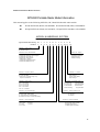
MODEL NUMBERING SYSTEM
Typical Model Numbering: M
Position: 1
1
2
2
3
P
4
C
5
N
6
6
7
T
8
Z
9
5 A Z
10 11 12
Position 1 - Type of Unit
H = Hand-Held Portable
M = Mobile Product
Positions 2 and 3 - Model Series
02=Motorola
06=Motorola
07=Motorola
08=Motorola
12=Motorola
13=Motorola
39=Motorola
Digital Communicator
Advanced Feature Digital
i370 Products
i1000 Products
3:1 Mobile
Ruggedized Digital
MTH500 Family
Position 12 - Unique
Model Variations
N=Standard Package
R=Blue Housing
Z=Black Housing
Position 4 - Frequency Band
Position 11 - Version
P=380 to 400 MHz
Q=410 to 430 MHz
*Values given represent range only;
they are not absolute.
Version Letter (Alpha) Major Change
Version Letter (Beta)
Major Change
Position 5 - Power Level
A=0 to 0.7 Watts
B=0.7 to 0.9 Watts
C=1.0 to 3.9 Watts
D=4.0 to 5.0 Watts
E=5.1 to 6.0 Watts
F=6.1 to 10.0 Watts
Position 6 - Physical Packages
F=Limited Keypad - With Display
H=Full Keypad - With Display
K= Limited Controls - Basic Display
N=Enhanced Controls - Enhanced Display
Position 7 - Channel Spacing
1=5 kHz
2=6.25 kHz
3=10 kHz
4=12.5 kHz
5=15 kHz
6=25 kHz
7=30 kHz
Position 10 - Feature Level
1=Basic
2=Limited Pkg
3=Limited Plus
4=Intermediate
5=Standard Pkg
6=Standard Plus
7=Expanded Pkg
8=Expanded Plus
9=Full Feature/
Programmable
Position 9 - Primary System Type
R=iDEN Basic
S= iDen AFU
Z= Dimetra
Position 8 - Primary Operation
N=Digital Front
Q=Low Profile -Basic Display
R=Digital Multi-Service
T=TDMA Digital Dual Mode
ix
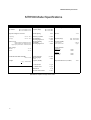
MTH500 Model Specifications
MTH500 Model Specifications
GENERAL
ETSI
Type Number:
RECEIVER
ETS 300 394-1
R1: 380-400 MHz: PT811F
R2: 410-430 MHz: PT511F
Temperature Range for Transceiver:
Receiver Type:
TRANSMITTER
Class A and B
Frequency Range:
R1: 380-400 MHz
R2: 410-430 MHz
Channel Spacing:
25 kHz
Modulation Type:
RF Power
Operating:
-20°C to +60°C
Sensitivity (4%) BER:
-112 dBm
Storage:
-40°C to +85°C
Intermodulation:
Interfering Signal Level:
(4%) BER
-47 dBm
Frequency Range:
Battery Types:
Standard SNN5705B 800mAH (LiIon)
Standard SNN5705C 800mAH (Lilon)
High Capacity SNN5706A 1100mAH (LiIon)
Selectivity Blocking:
(50-100 kHz)
Interfering Signal Level:
(4%) BER
Frequency Stability:
Locked to Base
Not Locked to Base
Battery Voltage:
Minimum:
3.4 Vdc
Nominal:
3.8 Vdc
Portable Dimensions HxWxD in MMs:
140x55x31 mm
-40 dBm
Spurious Emissions
Conducted
30MHz-1GHz
1GHz-4GHz
Radiated
30MHz-1GHz
1GHz-4GHz
Spurious Rejection:
Interfering Signal
Level:
0.2 ppm
Unlocked to Base
2.0 ppm
0.5 W
5% Max.
Specifications subject to change without notice.
x
± 100 Hz
± 2 ppm
-36dBm
-30dBm
-36dBm
-30dBm
Adjacent Channel Power (at± 25kHz)
Locked to Base
Distortion at Rated Audio:
R1: 380-400 MHz
R2: 410-430 MHz
-45 dBm
<155gr, without battery
Audio Rated:
1 Watt
(4%) BER
Frequency Stability:
Weight:
p/4DQPSK
– 60 dB
MTH500 Portable Radio Basic Service Manual- OVERVIEW
CHAPTER 1
OVERVIEW
To achieve a high spectrum efficiency, the MTH500 uses digital modulation technology and sophisticated voice-compression algorithm. The voice of the person
speaking into the microphone is converted into a digital bit stream consisting of
zeros (0) and ones (1). This stream is then modulated into a radio-frequency (RF)
signal, which is transmitted over the air to another radio. The process is called digital modulation.
Digital Modulation Technology
The MTH500 is a portable radio that has two models operating in two different
frequency ranges: R1: 380-400 MHz and R2: 410-430 MHz. These radios can
operate in dispatch and phone mode. Also, these radios can operate in TMO
(Trunked Mode Operation) and DMO (Direct Mode Operation) modes. It uses
two digital technologies: p/4 DQPSK and Time Division Multiple Access
(TDMA).
p/4 DQPSK is a modulation technique that transmits information by altering the
phase of the radio frequency (RF) signal. Data is converted into complex symbols,
which alter the RF signal and transmit the information. When the signal is
received, the change in phase is converted back into symbols and then into the
original data.
The system can accommodate 4-voice channels in the standard 25 kHz channel as
used in the two-way radio.
Time Division Multiple Access (TDMA) is used to allocate portions of the RF
signal by dividing time into four slots, one for each unit.
Time allocation enables each unit to transmit its voice information without interference from other transmitting units. Transmission from a unit or base station is
accommodated in time-slot lengths of 15 milliseconds and frame lengths of 60
milliseconds. The TDMA technique requires sophisticated algorithms and a digital signal processor (DSP) to perform voice compressions/decompressions and
RF modulation/demodulation.
1
OVERVIEW: Voice Compression Technology
Voice Compression Technology
Voice is converted into a digital bit stream by sampling the voice at a high rate
and converting the samples into numbers, which are represented by bits.
Voice compression reduces the number of bits per second while maintaining the
voice at an acceptable quality level. The MTH500 uses a coding technique called
ACELP (Algebraic Code Excited Linear Prediction). The compressed voice-data
bits modulate the RF signal.
Description
Transceiver Description
All the radio circuitry is contained in the Digital/RF Board and the keypad board. The Digital/RF board is divided
into the following sections: digital, frequency generating, transmitter, and receiver.
Digital Section Description
The digital section includes the Redcap 2 that consists of the Mcore risk machine and the Digital Signal Processor
(DSP).
The Mcore is the controller of the Digital/RF Board. It controls the operation of the transmitter, receiver, audio,
and synthesizer integrated circuits located in the RF section. It communicates with the keypad and display.
The Digital Signal Processor (DSP) performs modulation and de-modulation functions for the radio. It also performs Forward Error Correction and other correction algorithms for overcoming channel errors and ACELP
speech coding. It carries out linear 16-bit analog to digital conversions, audio filtering, and level amplification for
the microphone audio input and the received audio output.
The power and audio section is based on the GCAP III and includes power supplies, 13-bit CODEC, audio routing,
microphone and ear piece amplifiers. A audio power amplifier is used for the loud speaker.
2
MTH500 Portable Radio Basic Service Manual- OVERVIEW
Transmitter Path Description
The transmitter circuitry includes a linear class AB Power Amplifier (PA) for the linear modulation of the
MTH500. It also includes a novel cartesian feedback loop to enhance its transmitter linearity and reduced splattering power into adjacent channels.
The transmitter path consists of a novel cartesian feedback loop that contains the forward and loop feedback paths.
The forward path includes the low noise ODCT (Offset Direct Conversion Transmitter), Balun, Attenuator, and
Power Amplifier. The loop feedback path includes the directional coupler, attenuator, and LNODCT (Low Noise
Offset Direct Conversion Transmitter) ASIC.
The cartesian Feedback output power passes to the antenna through the Isolator, Antenna Switch, and Harmonic
Filter.
Receiver Path Description
The receiver path includes the Antenna Switch, SAW, LNA, ceramic filter, mixer, Crystal Filter, and WPIC
(World Phone IC). The first IF consists of the Crystal Filter and WPIC ASIC.
Frequency Generating Section Description
The frequency generating section provides description of the following main components: Fractional-N Synthesizer, REF. oscillator, Main VCO, WPIC ASIC Synthesizers, LNODCT ASIC Synthesizer, External Offset and
second LO Synthesizer, DSP PLL, and Host PLL.
3
OVERVIEW: Description
THIS PAGE INTENTIONALLY LEFT BLANK
4
MTH500 Portable Radio Basic Service Manual - TEST SETUP & TESTING
CHAPTER 2
TEST SETUP & TESTING
!
WARNING
Any level 3 repairs can deeply affect the performance of
the MTH500 radio and may cause a new tuning procedure. This tuning procedure can be applied by certain
authorised Motorola depots where the appropriate
TEST & TUNE EQUIPMENT is available.The appropriate TEST & TUNE EQUIPMENT is a special automated
test equipment which is only available at some Motorola
factories and Motorola repair centers.
Before Testing
Carry out the following instructions before testing:
• Check that you have a fully charged battery (Not required when using Battery
Eliminator WALN4097).
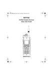
• Connect an RF cable to the N-type RF Connector of the IFR
• Connect the other side of the RF cable to the antenna adapter assembly
(Motorola Part Number FLN9659). Connect the RF cable to the other side of
the antenna assembly connector.
5
TEST SETUP & TESTING: Typical Test Setup
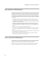
Typical Test Setup
IFR 2968
Antenna Adapter
Assembly
(FLN9659)
N-Type RF
Connector
MTH500
RF Cable
Battery
Eliminator
(WALN4097)
3.8 V
Power
Supply
Figure 1. Typical Test Setup
6
MTH500 Portable Radio Basic Service Manual - TEST SETUP & TESTING
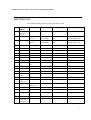
Test Check List:
The following table summarises the required test setups.
No.
Test
Name
1.
Base Station Registration
Test Setup
Radio Setup
Test Conditions
Limits
Traffic
Channel
390.125 MHz
422.0125 MHz
3605
880
TETRA 380+OMS for R1
TETRA 410MS for R2
Control
Channel
390.125 MHz
422.0125 MHz
3605
880
TETRA 380+OMS for R1
TETRA 410MS for R2
Time Slot
3
Country Code
753
Network Code
2361
Base Color
1
Location Area
22
Min Rx Level
-110dBm
Max Tx Level
30dBm
Access Parameter
Mobile Power
2.
Receiver
RSSI
3.
Transmitter
Burst Power
4.
-53dBm
30dBm
Burst Type
Normal
RF Gen Level
-80dBm
RF Gen Level
Burst Power
-90dBm
28-32dBm
Timing Error
<=0.25 Symbols
Vector Error
Max 10% RMS, 30% Peak
Frequency Error
-/+ 100Hz
Call
Processing
Talk Back
7
TEST SETUP & TESTING: Typical Test Setup
No.
Test
Name
Test Setup
Radio Setup
1KHz Test
Signal
Group Mode
5.
Test Conditions
-50dBm
Call
Processing
Call to Mobile
Private
4 digit random
number & “Send”
RF Gen Level
Burst Power
28-32dBm
-90dBm
28-32dBm
Timing Error
<=0.25 Symbols
Vector Error
Max 10% RMS, 30% Peak
Frequency Error
-/+ 100Hz
Receiver Tests
1.
Simulate Base Station (registration)
2.
RSSI
Transmitter Tests
1. Power Burst (Control Range)
2. Power Profiles
3. Tx Burst Timing Error
4. Vector Error RMS and Peak
5. Tx Frequency Error
Call Processing Tests
1. Talk Back
2. Call to Mobile
8
Limits
MTH500 Portable Radio Basic Service Manual - TEST SETUP & TESTING
Duplex Test
1. Digital Duplex Test (Tx)
Measurement Capabilities:
Bar charts (Tx Power, Freq. Err, Vector Rms.), Spectrum Analyser, Power Analyser, Vector Analyser, Vector Diagrams
How to Configure the IFR 2968 Setup
Perform the following steps to configure the IFR 2968 with the radio set:
1. Turn ON the IFR.
2. Press “Systems” Mode Key (wait until the digital system is initialised).
3. Press the “Tetra Mobile” soft key.
4. Press the “Setup” soft key and enter the System Parameters Screen.
5. Press the “Channel Plan” soft key.
6. Press “Tetra 380+OMS” soft key for R1 or “Tetra 410MS” soft key for R2.
The “Control Channel” automatically changes to “3600” for R1 or “800” for
R2; and “Traffic Channel” automatically changes to “3700”for R1 or 900 for
R2.
7. Press twice the “Traffic Channel” soft key and check that the marker goes to
Timeslot. Press Data key “3” followed by the “Traffic Channel” soft key, to
change to Timeslot “3”.
8. Press “Country Code” soft key. Enter “753” and “Country Code” soft key.
9. Press “Network Code” soft key. Thereafter, enter “2361” and press “Network
Code” soft key.
10. Press “Base Color” soft key. Thereafter, enter “1” and press “Base Color” soft
key.
11. Press “More” soft key.
12. Press “Location Area” soft key. Thereafter, enter “22” and press “Location
Area” soft key.
9
TEST SETUP & TESTING: Typical Test Setup
13. Press “Min Rx Level” soft key. Thereafter, enter “-110dBm” and press “Min
Rx Level” soft key.
14. Press “Max Tx Level” soft key. Thereafter, enter “30dBm” and press “Max
Tx Level” soft key.
15. Press “Access Parameter” soft key. Thereafter, enter “-53dBm” and press
“Access Parameter” soft key.
16. Press “Test Mode” soft key. Press “Enable” soft key.
17. Press “Base Service” soft key and “Supported” soft key.
Note: You are entering base services setup.
The displayed values are factory defaults and should not be changed.
Power On Registration: required
Power Off Deregistration: required
Priority Cell: yes
Minimum Mode Service: may be used
Migration: supported
System Wide Services: normal mode
18. Press “More” soft key.
TETRA Voice Services: supported
Circuit Mode Data Service: supported
(Reserved): available
SNDCD Service: available
Air Interface Encryption: not available
Advanced Link: not supported
19. Press the “Return” soft key.
20. Press the “Neighbr Cell” soft key.
21. Verify that the following NEIGHBOUR CELL INFO values are displayed:
10
MTH500 Portable Radio Basic Service Manual - TEST SETUP & TESTING
Note: The displayed values are factory defaults and should not be changed.
NEIGHBOUR CELL BROADCAST: NOT REQUIRED
BROADCAST INTERVAL: 10s
NEIGHBOUR CELL CHANNEL: 0000
NEIGHBOUR CELL LOCATION AREA: 00000
NEIGHBOUR CELL IDENTIFIER: 01
SLOW RE-SELECT THRESHOLD: 10dB
PRESS “MORE” SOFT KEY
SLOW RE-SELECT HYSTERESIS: 10dB
FAST RE-SELECT THRESHOLD: 10dB
FAST RE-SELECT HYSTERESIS: 10dB
22. Press the “Return” soft key.
23. Press the “Trunk Type” soft key and “Tx Trunked” soft key.
24. Press “More” Softkey.
Note:
The displayed values are factory defaults and should not be changed.
It is not required to configure “Call Types” and “Messages”.
25. Press “More” Softkey.
How to Configure the IFR 2968 Manual Test Screen
1. To enter “Manual test” screen, press “Manual” soft key.
2. Press “Control Channel” soft key. Thereafter, enter “3605” for R1 and “880”
for R2 and press “Control Channel” soft key (IFR 3605 = Rx 390.125MHz)
for R1 and (IFR 880 = Rx 422.0125MHz) for R2.
11
TEST SETUP & TESTING: RF Tests
3. Press “Traffic Channel” soft key. Enter “3700” for R1 and “900” for R2 and
press “Traffic Channel” soft key. The marker goes to Timeslot. Enter “3” and
press “Traffic Channel” soft key. (Note that the Traffic Channel number
changes automatically after entering the Control Channel number).
4. Press “RF Gen Level” soft key. Thereafter, enter “-50” and press “dBm” data
keys followed by “RF Gen Level” soft key.
5. Press “Mobile Power” soft key, enter 30 dBm/1W, using soft key.
6. Press “Burst Type” soft key and “Normal” soft key.
7. This completes the test equipment configuration setup.
Note: The System Setup Configuration Data is saved even after the power is
turned off. However, the Manual Test Setup is not saved.
RF Tests
Receiver Tests
Simulate Base Station (registration)
1. Turn the radio ON
2. Check that registration and “ITSI: ---/----/00000xxx” is displayed on the IFR
“Manual Test” screen.
Status: Registered (ITSI Attach)
RSSI Test
Before carrying out the following steps, record the Insertion loss (dB) of the cable
loss value - (X) dB. Also, 0.5 dB, the maximum insertion loss of the Antenna
assembly adapter should be added to the total calculated insertion loss.
1. In the IFR Manual Test Mode, press the “RF Gen Level” Soft Key and enter
(–) 80dbm.
12
MTH500 Portable Radio Basic Service Manual - TEST SETUP & TESTING
2. Before testing, the radio should be configured to RSSI mode using the following Sequence, When performing steps 3 thru 6, make sure that you press the
handset keys sequentially (less then a second between every consecutive
press).
3. Press the “Volume down” Key.
4. Press the “1 “key, and “Menu” Key.
5. Press the “2 “key, and “Menu” Key.
6. Press the “3 “key.
Hereafter, there is no need for quick sequence of pressing the handset keys.
7. Press
Key to enter the “4 Cells Info” state.
.
8. Press “OK” using the Right ( ) Key and press
.
.
9. Press “Trace” using the Right ( ) Key.
Note: RSSI results will flash on the screen every few seconds.
The display shows: SERV: xx
RSSI: -81
SQE: xx
Disregard the “SERV” and “SQE” results.
The actual measured result should be:
{-80dBm (IFR RF Gen Level) -0.5dB(adapter)-XdB (cable)} +/-1 dB.
RSSI = {Radio RSSI Result – [Antenna assembly Adapter (dB) + Insertion loss
of the Cable (dB)]}.
To stop the “Trace” process, perform the following. When performing steps 10.
thru 13., make sure that you press the handset keys sequentially (less then a second between every consecutive press):
10. Press the “Volume down” Key.
11. Press the “1” key, and “Menu” Key.
12. Press the “2” key, and “Menu” Key.
13. Press the “3” key.
.
14. Press “Stop” using the Right ( ) Key.
13
TEST SETUP & TESTING: Call Processing Test
.
15. Press “Back” twice using the Left ( ) Key.
Transmitter Tests
1. Change the “Mode Key” of the radio to “Group Mode”.
2. Press the “RF Gen Level” soft key. Enter “-90dBm” by pressing the data keys
and “RF Gen Level” Key.
3. Press the “PTT” of the radio and monitor the IFR “Manual Test” screen which
displays the Burst Power, Power Profile, Timing Error, Vector Error, and Frequency Error.
Note: You have to hold the PTT in the pressed position long enough to enable you
to read the results.
- Burst Power Required Results: 28-32dbm.
- Power Profile: Passed.
- Timing Error: < 0.25 symbols.
- Vector Error: Max 10% RMS, Max 30% Peak.
- Max 5% residual.
- Frequency Error: -/+ 100Hz.
4.
Press the “Clear Down” soft key, to proceed with other tests.
Call Processing Test
Talk Back
Before you start this test, make sure that handset and test equipment are configured the same as given in the Transmitter Test.
1. Press the “PTT” and speak into the mic of the radio. You will hear the last
three seconds of the speech frames before the “PTT” is released.
14
MTH500 Portable Radio Basic Service Manual - TEST SETUP & TESTING
2. Press the “Test Sound” soft key to provide the 1kHz signal to the radio
speaker.
3. Press the “Silence” soft key to mute the 1KHz Audio Signal of the speaker.
4. Press the “Clear Down” soft key and check that the “Cleardown Complete”
status appear on the IFR “Manual Test” screen.
Call to Mobile
1. Press the radio “Mode” key and change to “Private” mode.
2. Press the “Call Mobile” soft key on the IFR.
Note: Select type of call.
3. Press “Private” Call.
Note: You will hear beeps from the handset speaker.
4. Press “Abort Call” soft key.Duplex Test (Phone/Privet Mode)
Digital Duplex Test (Tx)
1. Press the “Mode” key of the radio and select “Phone” or “Privet” mode.
2. Dial a random number “9359” using the Alphanumeric keys of the radio and
press the “Send” Key.
The following results are displayed on the IFR “Manual Test” Screen.
- Burst Power Required Results: 28-32dbm
- Power Profile: Passed
- Timing Error: <0.25 Symbols.
- Vector Error: Max 10% RMS, Max 30% Peak.
- Max 5% residual.
- Frequency Error: -/+ 100Hz
15
3. Speak into the Handset Microphone and hear your speech (after a short delay)
from the handset Earpiece.
Note: If you need more details, press the “Duplex Test” mode key.
4. Press the “duplex test (Tx)” soft key twice. The “Digital Duplex test” results
will be displayed on the IFR screen providing you with the following bar
charts measurement capabilities:
- Power
- Vector RMS
- Frequency Error
For Power Analyser Graph:
5. Press “power ana” soft key.
6. Check that the power frame falls within the limits.
For Spectrum Analyser Graph:
7. Press “Spect ana” soft key.
8. Monitor the Tx frequency.
For Vector Analyser Diagram:
9. Press the “Vect Anal” soft key
10. Monitor the constellation diagram.
11. Press the “Vector Diagram” soft key.
12. Press the “Rotated vector” to zoom in on the constellation.
13. Press the handset “End” key.
16
MTH500 Portable Radio Basic Service Manual - TEST SETUP & TESTING
DMO Test
IFR 2968 Test Setup
1. Press the “System” softkey.
2. Press “TETRA Direct” Softkey.
3. Press “Setup” Softkey.
4. Press “Channel Plan” Softkey, press “TETRA 380+ODM” softkey for R1or
TETRA 410+ODM for R2.
5. Press DM Tx Mode” softkey, press “discontinue” softkey
How to Configure the IFR 2968 Manual Test Screen
1. Press the “Manual” softkey.
2. Press “Channel” Softkey, thereafter enter “4000= 390 MHz” for R1or
“1200=420 MHz for R2 and press “Channel” softkey.
3. Press “Expected Power” Softkey, enter 30.0dBm/1.0 w.
4. Press “Burst Type” Softkey and “Normal” softkey.
Radio Configuration for DMO
Modify the radio for DMO option by carrying out the following sequence:
1. Turn ON the radio.
2. Press the “Menu” key
3. Press
key and select mode “network”, press “OK” softkey.
4. Select “OPERMODE”, and press “OK” softkey.
5. Select “DIRECMODE” softkey and press “OK” softkey
.
17
TEST SETUP & TESTING: DMO Test
RF Test - Transmit Test
Hold the PTT in the pressed position long enough to enable you to read the
results:
•
•
•
•
18
Results: - Power Profile: Passed
Burst Power Request Results: 28-32 dBm
Frequency Error: +/- 100Hz max.
Vector Error: Max. 10% RMS, Max. 30% Peak, Max. 5% Residual.
MTH500 Portable Radio Basic Service Manual - PROGRAMMING THE RADIO
CHAPTER 3
PROGRAMMING THE RADIO
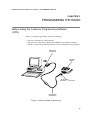
Before Using the Customer Programming Software
(CPS)
Before you begin programming, ensure the following:
• That your radio battery is fully charged.
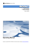
• That you have connected the Data cable (FKN4897), according to Figure 2.
• That the Customer Programming Software (CPS) is installed in your computer.
p
Serial Port
(COM1/2)
MTH500
Radio
To MTH500
Accessory Connector
Data Cable
(FKN4897)
Figure 2. Setup for Radio Programming.
19
PROGRAMMING THE RADIO: Programming the Radio
Programming the Radio
1. Verify that the radio is turned off.
2. Run the Customer Programming Software (CPS) on your computer.
3. Press the “1” and “9” keys together and then the On/Off key for about 3 seconds. Verify that no display appears on the LCD screen.
4. Click the Toolbar “Read Phone” icon. Refer to the CPS Application Window
Screen in the CPS User Guide, Publication No. 68P02956C20. The setup
enters an initialization process that takes about 20 seconds. After that, a reading process starts.
Note: While reading is in progress, the radio screen displays the following data:
Diag. SW Ver. 01.01
HW ID Code: XXX
Flash: TE28F320C3BA
Command READ REQ.
--Done-00:00:00
Appears at the
end of the process
Elapsed Time
Indication
A progress bar appear on the computer screen. After the reading process is
finished, the radio Codeplug screen appears.
CodePlug Programming
1. On the menu bar, click “File” “Open”.
2. Browse for the required Codeplug file and open the file.
3. The Codeplug window appears on the screen.
4. Click the Toolbar “Tools” and select “Write Entire Codeplug”.
20
MTH500 Portable Radio Basic Service Manual - PROGRAMMING THE RADIO
5. Press “Yes” icon.
Note: The Codeplug is now being written into the radio. A progress bar is displayed on the computer screen showing the writing status.
After a successful writing, the message “The Operation Was Successful”
appears on the computer screen.
6. Press the OK button.
Application Programming
1. On the menu bar click “Tools”, “Write Software”.
2. Press “Continue” icon.
Note: The Codeplug reads data from the radio. A progress bar is displayed on the
computer screen showing the writing status.
After a successful reading, the “Write Software to Phone” appears on the
computer screen.
3. Choose the Customized Choice” option.
4. Browse for the required application file and select it.
5. Press the “Write” button.
Note:The Codeplug is now being written into the radio. A progress bar is displayed on the computer screen showing the writing status.
After a successful writing, the message “The Operation Was Successful” appears
on the computer screen.
6. Press the “Cancel” button.
7. Click the Toolbar “R” (Reset) icon.
21
PROGRAMMING THE RADIO: Manual Mode Testing
Manual Mode Testing
Preparation for Testing
1. Verify that the radio is turned off.
2. Press the “4”, “5” and “6” keys together and then, press the On/Off key to turn
the radio on.
3. The display shows “LCD Test Press Any Key To Proceed”.
TESTS
Note: Any key that will be pressed will cause the test to advance from one step to
the next.
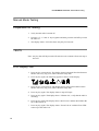
LCD Display Test
1. Press any key consecutively. The display shows horizontal lines that becomes
thicker with every key press, until it becomes fully dark.
2. Press any key again, the following appears at the top of the display:
3. Press any key consecutively. The display shows vertical lines that becomes
thicker with every key press, until it becomes fully dark.
4. Press any key again. The display shows a map of Europe.
5. Press any key again. The display shows “Vibrator On”, verify that the radio is
vibrating.
6. Press any key again. The display shows “Red Led on” and the Red LED at the
top of the radio is lit.
7. Press any key again. The display shows “Green Led on” and the Green LED
at the top of the radio is lit.
22
MTH500 Portable Radio Basic Service Manual - PROGRAMMING THE RADIO
8. Press any key, the LED located on the top of the radio (near the antenna),
turns ON, and the two halves of this LED starts blinking with RED and Green
lights.
9. Press any key again. The display shows “Backlight On” and the display backlight is On.
10. Press any key again. The display shows “Speaker Tone Test”, a tone is heard
via the speaker.
11. Press any key again. The display shows “Earpiece Tone Test”, a tone is heard
via the earpiece.
12. Press any key again. The display shows “Audio Loopback Test”, speak into
the microphone, you should hear your voice via the earpiece.
13. Press any key again. The display shows “Chopper-Noise Test”, a low hum is
heard via the earpiece.
14. Press any key again. The display shows all the radio keys.
15. Press every key, one by one. Each key you press causes its respective display
to disappear.
16. Press
disappear.
Key. Every time you press causes the respective display to
17. After pressing all keys, the display is clear.
18. Turn the radio Off.
Charger Recognition Test
• Turn the radio ON.
• Connect the Rapid Travel Charger accessory connector to the handset. Check
whether the LCD display shows “charger connected” and that the keypad backlight is turned ON.
• Connect the Vehicle Power Adapter (VPA) Charger accessory connector to the
handset. Check whether the LCD display shows “charger connected” and that
the keypad back-light is turned ON.
• Connect the handset to the Desktop Charger. Check whether the LCD display
shows “charger connected” and that the keypad back-light is turned ON.
• Place the handset in the Digital Car Kit cradle. Verify that the car ignition
switch is turned ON. Check whether the LCD display shows “Car it connected”, and that the keypad back-light is turned ON.
23
PROGRAMMING THE RADIO: TESTS
• Verify that the battery charger is in progress (the process advance is indicated
on the Battery Strength icon).
Press the “ON/OFF” key. The radio should turn OFF.
24
MTH500 Portable Radio Basic Service Manual - PROGRAMMING THE RADIO
Service Flowchart
Connect the radio to
the IFR (1)
1
Fail
Maintenance
level?
Perform all
tests: RF and audio
Pass
Fail
1
Replace
Main board
(*) and re-test
- Replace the customer’s radio
- Send the radio to Level 3 maintenance
- Send the new TEI number to service provider
- Clone/reprogram customer details to new unit
Fail
Pass
Replace
other kits one-by-one
and re-test
- Replace battery
- Replace antenna
Pass
- Send new TEI number to the
service provider
- Clone/reprogram, customer
details to new unit
(1) Refer to Replacement Kit table
in Appendix.
(*) Main Board: See Radio Replacement Parts List (Appendix A)
Note: Not field replaceable for Latin America
25
PROGRAMMING THE RADIO: Service Flowchart
This page left blank intentionally
26
MTH500 Portable Radio Basic Service Manual - MAINTENANCE
CHAPTER 4
MAINTENANCE
Preventive Maintenance
This portable radio does not require a scheduled preventive maintenance program. However, periodic visual inspection is recommended.
Inspection
Inspect the radio’s external surfaces. A detailed inspection of interior circuitry is not
needed or recommended.
Cleaning
The following procedures describe the recommended cleaning agents and methods to be
used when cleaning the external and internal surfaces of the radio. External surfaces
should be cleaned whenever a periodic visual inspection reveals the presence of smudges,
compound, or grime. Internal surfaces (circuit boards and components) should be cleaned
only when the radio is disassembled for servicing or repair.
The only recommended agent for cleaning external radio surfaces is a 0.5% solution (one
teaspoon of detergent per gallon of water) of mild dishwashing detergent in water. The
internal surfaces should be cleaned only with isopropyl alcohol (70% by volume).
27
MAINTENANCE: Safe Handling of CMOS Devices
Safe Handling of CMOS Devices
Complementary metal-oxide semiconductor (CMOS) devices are used in the radio. While
the attributes of CMOS devices are many, their characteristics make them susceptible to
damage by electrostatic or high voltage charges. Damage can be latent, resulting in failure
occurring weeks or months later. Therefore, special precautions must be taken to prevent
device damage during disassembly, troubleshooting, and repair. The following handling
precautions are mandatory for CMOS circuits, and are especially important in low humidity conditions.
• All CMOS devices must be stored or transported in conductive material so that all
exposed leads are shorted together. CMOS devices must not be inserted into conventional plastic “snow” or plastic trays of the type that are used for storage or transportation of other semiconductor devices.
• All CMOS devices must be placed on a grounded bench surface and the technician
must also be grounded before handling the devices. This is done most effectively by
having the technician wear a conductive wrist strap in series with a 100kW resistor to
ground.
• Do not wear nylon clothing while handling CMOS circuits.
• Do not insert or remove CMOS devices with power applied. Check all power supplies
to be used for testing CMOS devices and be certain there are no voltage transients
present.
• When straightening CMOS device leads, provide ground straps for the apparatus used.
• When soldering, use a grounded soldering iron.
• All power must be turned off in a system before printed circuit boards containing
CMOS devices are inserted, removed, or soldered.
Level 1 and Level 2 Maintenance
This manual covers Level 1 and Level 2 Maintenance: at Level 1 maintenance you replace
the radio and/or accessories and send the faulty unified chassis and/or accessories to a
higher level of maintenance; at level 2 maintenance a faulty kit is replaced.
Note: For Level 1 maintenance instructions refer to the information given in Chapter 2.
For Level 2 maintenance also refer to Chapter 2, and the instructions given below.
28
MTH500 Portable Radio Basic Service Manual - MAINTENANCE
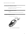
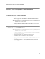
Removing and Installing the Antenna
The antenna must be removed each time the back housing is removed.
Recommended tools: no tools are required.
To remove the antenna from the unit:
(See Figure 1)
1. Unscrew the antenna counter clockwise until it is detached from the handset.
To install the antenna in the unit
1. Screw the antenna clockwise to the handset.
Figure 1 Antenna Removal and Installation
29
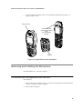
MAINTENANCE: Removing and Installing Battery Door and Battery
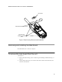
Removing and Installing Battery Door and Battery
Recommended tools: no tools are required
To remove the battery door from the unit:
(See Figure 2)
1. Place the unit facing down on the work area.
2. Press the battery door release button, slide the door towards the bottom of the unit
and lift it up from the unit.
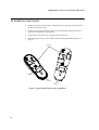
To remove the battery:
(See Figure 3)
1. Press the battery fastening bridge toward the upper side of the unit.
2. Simultaneously, using other hand, release the battery from its chamber.
To install the battery:
1. Locate the battery so that the lower part (coloured silver) is touching the lower wall
of the battery chamber.
2. Carefully press the battery down until it snaps into location.
To install the battery door:
1. Position the door on the unit over the battery so that the door release button is just
above the battery fastening bridge.
2. Slide the door upward until the door snaps into location.
3. Verify that the door is aligned with the handset back housing.
30
MTH500 Portable Radio Basic Service Manual - MAINTENANCE
Figure 2 Battery Door Removal and Installation
Figure 3 Battery Removal and Installation
31
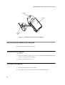
MAINTENANCE: Removing and Installing the Back Housing
Removing and Installing the Back Housing
Recommended tools: T-8 Torx bit, Torx driver, mini flat-tip screwdriver
To remove the back housing from the unit:
(See Figure 4)
1. Remove the antenna, refer to “Removing and Installing the Antenna” on page 29.
2. Remove the battery door and the battery, refer to “Removing and Installing Battery
Door and Battery” on page 30.
3. Place the unit facing down on the work area.
4. Using the screwdriver remove the oval label at the top of the unit and the tamper evident label in the center to enable access to all six screws fastening the back housing.
Clean the adhesive remains of the tamper evident label using alcohol.
5. Using the Torx driver with the T-8 Torx bit, unscrew the six screws fastening the
back housing.
6. Carefully remove the back housing from the unit.
To install the back housing:
1. Position the back housing over the unit.
2. Verify that the cover is positioned correctly, screw holes are aligned to the threads of
the front housing, external antenna connector is inserted into its dedicated hole, and
the styling groove of the back housing meets the styling groove of the front housing.
3. Set the Torx driver to 3.5 in-lb.
4. Screw the back housing screws in the following order: Upper left and right screws,
center left and right screws and lower left and right screws.
5. Glue a new oval label over the holes of the two upper screws and a new tamper evident label on the holes of the two center screws.
6. Install the battery and the battery door, refer to “Removing and Installing Battery
Door and Battery” on page 30.
32
MTH500 Portable Radio Basic Service Manual - MAINTENANCE
Oval Label
External Antenna Connector
Back Housing
Fastening Screws
(X6)
Figure 4 Back Housing Removal and Installation
Removing and Installing the Main Board
Recommended tools: no tools are required
To remove the main board from the unit:
(See Figure 5)
1. Remove the back housing, refer to “Removing and Installing the Back Housing” on
page 32.
2. Gently lift the main board, I/O connector side at the bottom of the board first, and
remove it from the unit.
33
MAINTENANCE: Removing and Installing the Main Board
To install the main board:
1. Position the main board in location. Verify that the two guide pins are inserted into
the holes in the main board.
2. Gently push the main board down and verify that the Board-to-Board connector is
properly connected to the keypad board.
3. Verify that the I/O rubber seal is properly located in the unit.
4. Install the back housing, refer to “Removing and Installing the Back Housing” on
page 32.
Main Board
PHF Cover
I/O Connector
Rubber Seal
Figure 5 Main Board Removal and Installation
34
MTH500 Portable Radio Basic Service Manual - MAINTENANCE
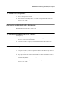
Removing and Installing the Keypad and LCD Boards
Recommended tools: mini flat-tip screwdriver
To remove the keypad and LCD boards from the unit:
(See Figure 6)
1. Remove the back housing, refer to “Removing and Installing the Back Housing” on
page 32.
2. Place the unit facing down on the work area.
3. Open the Personal Hands-Free Kit (PHF) jack cover (See Figure 5).
4. Using the screwdriver, remove the chassis assembly including the main board, keypad board and LCD board, out from the unit.
5. Place the chassis assembly, with the keypad and LCD boards facing down, on the
work area.
6. Remove the main board from the chassis assembly.
7. Insert the screwdriver into one of the slots in the upper side of the chassis assembly,
above the LCD board, and gently push the boards out from the chassis assembly.
8. According to the board to be replaced, open the required Zero Insertion Force (ZIF)
connector, release the flat cable and the board.
To install the keypad and LCD boards:
1. Place the keypad and LCD boards on the work area so that the ZIF connectors are facing up.
CAUTION: Care must be taken when installing the keypad and LCD boards on the
chassis. Failure to comply may result in tear of the flat cable between
the two boards.
2. Insert the flat cable into the ZIF connectors and close the connectors doors until a
click is heard.
3. Insert the LCD board between the two snags at the sides of the chassis assembly.
4. Push the LCD board down until it snaps into location.
5. Verify that the chassis center guide pin is properly located inside the hole in the LCD
board and that the snag at the top of the chassis is inserted into the slot of the board.
35
MAINTENANCE: Removing and Installing the Keypad and LCD Boards
6. Install the keypad board on the chassis assembly.
7. Verify that the keypad board is sited parallel to the chassis assembly.
8. Verify that the main board is fully installed with the rubber seal.
9. Turn the chassis assembly up side down.
10. Install the main board on the chassis assembly. Verify that the two guide pins are
inserted to the holes in the main board.
11. Verify that the guide pins are properly located and that the Board-to-Board connector
is properly connected to the main board.
12. Install the chassis assembly with the boards into the unit. Verify that the I/O connector rubber seal is properly located in the unit.
13. Install the back housing, refer to “Removing and Installing the Back Housing” on
page 32.
LCD Board
LCD Board
Release Slot
Flat Cable
Chassis Assembly
Board-to-Board
Connector
ZIF Connectors
Keypad Board
Figure 6 Keypad and LCD Boards Removal and Installation
36
MTH500 Portable Radio Basic Service Manual - MAINTENANCE
Removing and Installing the LCD Module Assembly
Recommended tools: no tools are required
To remove the LCD module assembly:
(See Figure 7)
1. Remove the LCD board, refer to “Removing and Installing the Keypad and LCD
Boards” on page 35.
Note: Do not touch the LCD module assembly in the active viewing area; fingerprints on
this surface cannot be easily removed.
2. Using your hand, gently disengage the right two snaps and rotate the LCD module
assembly to the left until it disengaged from the LCD board.
To install the LCD module assembly:
Note: Do not touch the LCD module assembly in the active viewing area; fingerprints on
this surface cannot be easily removed.
1. Locate the LCD module above the LCD board so that the two guide pins are aligned
with the holes in the LCD board.
2. Gently push the module down, right snaps first and then left snaps.
3. Verify that the snaps are located correctly inside the board slots.
4. Remove the protective film from the LCD glass. Verify that no damage exists on the
LCD glass.
5. Install the LCD board, refer to “Removing and Installing the Keypad and LCD
Boards” on page 35.
37
MAINTENANCE: Removing and Installing the Keypad
LCD Board
LCD Module
LCD Module
Snaps
(X4)
Figure 7 LCD Module Removal and Installation
Removing and Installing the Keypad
Recommended tools: no tools are required
To remove the keypad:
(See Figure 8)
1. Remove the chassis assembly, refer to “To remove the keypad and LCD boards from
the unit:” on page 35, steps 1 through 3.
2. Remove the keypad from the unit.
To install the keypad:
1. Install the keypad inside the front housing.
2. Verify that all the keys are properly inserted into their dedicated holes.
38
MTH500 Portable Radio Basic Service Manual - MAINTENANCE
3. Install the chassis assembly, refer to “To install the keypad and LCD boards:” on
page 35, steps 1 and 2.
Front Housing
Chassis Assembly
Including Main Board
And
LCD and Keypad
Boards
Keypad
Figure 8 Keypad Removal and Installation
Removing and Installing the Microphone
Recommended tools: no tools are required
To remove the microphone from the unit:
(See Figure 9)
1. Remove the chassis assembly, refer to “To remove the keypad and LCD boards from
the unit:” on page 35, steps 1 through 3.
2. Remove the microphone.
39
MAINTENANCE: Removing and Installing the Earphone
To install the microphone:
1. Insert a microphone into location.
2. Install the chassis assembly, refer to “To install the keypad and LCD boards:” on
page 35, steps 1 and 2.
Removing and Installing the Earphone
Recommended tools: mini flat-tip screwdriver
To remove the earphone from the unit:
(See Figure 9)
1. Remove the chassis assembly, refer to “To remove the keypad and LCD boards from
the unit:” on page 35, steps 1 through 3.
2. Using the screwdriver, remove the earphone from the unit. If the earphone was
detached from its bottom plate, remove the plate as well.
To install the earphone:
1. Using the screwdriver, remove the protective film from the adhesive layer at the earphone bottom plate. Remove the Acoustic Safety Rubber.
2. Insert the earphone into location. Verify that the two snags at the earphone sides are
properly located in their dedicated slots.
3. Gently push the earphone until it is firmly glued inside the front housing. Place the
Acoustic Safety Rubber.
4. Install the chassis assembly, refer to “To install the keypad and LCD boards:” on
page 35, steps 1 and 2.
40
MTH500 Portable Radio Basic Service Manual - MAINTENANCE
Earphone
Acoustic Safety Rubber
Front Housing
Microphone
Figure 9 Microphone and Earphone Removal and Installation
41
MAINTENANCE: MTH500 Unit - Exploded View
MTH500 Unit - Exploded View
MTH500 components are listed in the table below. The first column marked with a # sign provides you with the
call out numbers of the components as marked in Figure 10 and Figure 11.
MTH500 Components List
42
#
Description
Part/Kit
1
Front Housing Assembly (Black)
Front Housing Assembly (Blue)
0186163T07
0186163T08
2
Keypad Assembly
0186630T01
3
Chassis Assembly
See Figure 10
4
Back Housing Assembly (Black)
Back Housing Assembly (Blue)
0186396T04
0186396T05
5
Antenna 380-400 MHz (R1)
Antenna 410-430 MHz (R2)
8586381J03
8586381J02
6
Screw, Self Forming
0304637P17
7
Label, Back
5486278T01
8
Standard Battery Door Assembly (Black)
Standard Battery Door Assembly (Blue)
0186613T01
0186613T02
Extended Battery Door Assembly (Black)
Extended Battery Door Assembly (Blue)
0186239T01
0186239T02
9
LCD Module
7287702M01
10
Keypad Kit
FCN9090A
11
Flex LCD to Keypad
8486498T01
12
LCD Kit
FCN9797A
13
Chassis
2786168T01
14
Main Board (R1)
Main Board (R2)
See Service
Replacement Kit
Matrix in
Appendix A
MTH500 Portable Radio Basic Service Manual - MAINTENANCE
7
5
3
1
2
8
6 (X6)
4
Figure 10 Exploded View
43
MAINTENANCE: MTH500 Unit - Exploded View
13
12
14
9
10
11
Figure 11 Exploded View of Chassis Assembly
44
Replacement Parts
APPENDIX A
REPLACEMENT PARTS AND KITS
Damaged parts should be replaced with identical replacement parts.
Replacement Parts
For complete information on ordering required parts and kits, contact your local
customer service representative.
Level 3 Maintenance
EMEA Region
EMEA Radio Support Depots are level 3 service partners. The depots are capable of performing repairs down to component level where retuning is required. Contact your local
CGISS office for information.
Motorola European Radio Support Centre ERSC Phone: +49 6128 702618
Heinrich Hertz Strasse 1
D-65232 Taunusstein
Germany
ERSC Customer Information Desk available through the following service number:
Austria:
06 60 75 41
Italy:
Belgium: 08 00 72 471
Luxemburg:
Denmark: 80 01 55 72
Netherlands:
Finland:
08 00 11 49 10
Norway:
France:
05 90 30 90
Portugal
Germany: 01 30 18 75 24
Spain:
Greece:
00 80 04 91 29 020
Sweden:
UK:
08 00 96 90 95
Switzerland:
Ireland
18 00 55 50 21
Iceland:
or dial
+49 6128 70 2618
Please use these numbers for repair enquires only.
16 78 77 387
08 00 23 27
60 22 45 13
80 01 11 15
05 05 49 35
90 09 84 902
02 07 94 307
1 55 30 82
80 08 147
45
Level 3 Maintenance
Latin America Region
Latin America Radio Support Centers
The Customer Support is available through the following service centers:
Warranty and Repairs:
Motorola De Colombia Service Center
Carrera 7 No. 71-52
Torre B piso 13
Oficina 1301
Bogota- Colombia
(571) 376-6990
Motorola De Mexico Service Center
Bosques de Alisos #125
Col. Bosques de las Lomas
CP 05120 Mexico DF
5252576700
Piece Parts:
To order parts in Latin America and the Carribean:
7:00 A.M. to 7:00 P.M. (Central Standard Time)
Monday through Friday (Chicago, USA)
1-847-538-8023
Technical Support:
https://businessonline.motorola.com, go to Contact Us to request technical support
Motorola Parts (Accessories and Aftermarket Division AAD):
Attention: Order Processing
1313 E. Algonquin Road
Schaumburg. IL. 60196
Parts Identification:
1-847-538-0021 (Voice)
1-847-538-8194 (Fax)
Some replacement parts, spare parts, and/or product information can be ordered directly.
If a complete Motorola part number is assigned to the part, it is available from Motorola
Radio After market and Accessory Division (AAD). If no part number is assigned, the part
is not normally available from Motorola. If the part number is appended with an asterisk,
the part is serviceable by Motorola Depot only. If a parts list is not included, this generally
means that no user-serviceable parts are available for that kit or assembly.
46
Radio Replacement Parts List
Radio Replacement Parts List
Part/Kit Number
MTH500 Model Description
0186163T07
0186163T08
Front Housing Assembly (Black)
Front Housing Assembly (Blue)
0186630T01
Keypad Assembly
0186396T04
0186396T05
Back Housing Assembly (Black)
Back Housing Assembly (Blue)
8586381J03
8586381J02
Antenna 380-400 MHz (R1)
Antenna 410-430 MHz (R2)
0186613T01
0186613T02
Standard Battery Door Assembly (Black)
Standard Battery Door Assembly (Blue)
0186239T01
0186239T02
Extended Battery Door Assembly (Black)
Extended Battery Door Assembly (Blue)
7287702M01
LCD Module
FCN9090A
Keypad Kit
FCN9797A
LCD Kit
(See Service
Replacement Kit
Matrix below)
Main Board (R1)
Main Board (R2)
47
Accessories Replacement Parts List
Accessories Replacement Parts List
Kit Number
MTH500 Model Description
Batteries
FTN6030A
Extended battery, 1100mAh, LiIon, Black (with battery door)
FTN6037A
Extended battery, 1100mAh, LiIon, Blue (with battery door)
FTN6031A
Standard battery, 800mAh, LiIon, Black (with battery door)
FTN6038A
Standard battery, 800mAh, LiIon, Blue (with battery door)
Chargers
FLN9468A
Dual Pocket Desktop Charger
SPN4716B
Travel charger
SYN7455A
Plug Adapter UK for travel Charger
SYN7456A
Plug Adapter EU for travel Charger
FLN9469A
Vehicular battery charger
Vehicular Adapters
FLN2850A
Car Kit
FLN9569A
Stand alone car cradle
Audio accessories
WADN4184A
Headset with Boom mic and in line PTT
FLN9470A
Headset with Boom mic (On Hold)
FLN9568A
PHF
Carrying Accessories
FLN9476A
Soft leather carry case
FHN6246A
Belt clip
Others
FKN4897A
48
Data cable
Recommended Programming Equipment
Recommended Programming Equipment
Name
Part Number
MTH500 CPS
PMVN4065B
Data Cable
FKN4897A
Service Replacement Kit Matrix (1)
Sales Model
Description
MTH500 Black
380-400 MHz
PT811F
MTH500 Blue
380-400 MHz
PT811F
MTH500 Black
410-430 MHz
PT511F
MTH500 Blue
410-430 MHz
PT511F
Service
Tanapa
Description
FUF1208AS
MTH500 Black
S/T R1 CLEAR
FUF1210AS
MTH500 Black
S/T R1 TEA1
FUF1211AS
MTH500 Black
S/T R1 TEA2
FUF1209AS
MTH500 Blue
S/T R1 CLEAR
FUF1212AS
MTH500 Blue
S/T R1 TEA1
FUF1213AS
MTH500 Blue
S/T R1 TEA2
FUF1222AS
MTH500 Black
S/T R2 CLEAR
FUF1222AS
MTH500 Black
S/T R2 TEA1
FUF1225AS
MTH500 Black
S/T R2 TEA2
FUF1222AS
MTH500 Blue
S/T R2 CLEAR
FUF1226AS
MTH500 Blue
S/T R2 TEA1
FUF1227AS
MTH500 Blue
S/T R2 TEA2
Note: All models listed in the Service Tanapa Column
are not field replaceable for Latin America
49
Service Replacement Kit Matrix (1)
This page left blank intentionally
50