1
Reference
Dimensions
and Weights. . . . . . . . . . . . . . . . . . .REF-1
Tools
REF-2
Maintenance Techniques. . . . . . . . . . . . . . . . . . .REF-4
Motorcycle Chemicals and Lubricants. . . . . . . . .REF-S
MOTTestChecks
REF-6
Storage
REF-10
Dimensions
"..'!i
and Weig
hts
r'
Wheelbaee(W)
2O75nWT1
I
.
......
S.TandVmodels
L, M. N, P and R models
;...
};;:,. ~.~
Overall
height
Seat
height
(S)(H)
Minimumgroundclearance. . . .,.. . . . . , ,. ...
Weight (dry) . . . . . . . . . . . . ..
..
::c
,. """:':'~
,! ;...
... .. .. ... ..
: ;',.
",..!,..,.,.,,!,::,
.
.. .
REF-12
i
. . . . . . . . .REF-20
. . . ... . . . . . . . . .REF-24
REF-28
Index. . . . . . . . . . . . . . . . . . . . . .. . . . . . . . . . . .REF-29
1410nvn
I
Kmodels
Technical Terms Explained.
Conversion Factors
,
1
Overaillength(L)
Overallwidth
FaultFinding
FaultFindingEquipment. . . . .
REF-1
725 mm
755 mm
745mm
1045 mm
790 mm
155 mm
169 kg
Tools
REF.2
Buying tools
At
.?O
Ik t
"
"
f
d
t I
I
I IS a u~. amen a requ remen
tf
.&
.
,poor
or
servicing and repaJnnga motorcycle. Although
Warning:To avoid the risk of a
quality tool breaking in use,
causing Injuty or damage to the
com
ent befi worked on
the Haynes Motorcycle WorkshopPractice
Manual (Bk. No. 1454).
there will be an initial.e~pens~in ~uilding up alwaysaim to :rchase t::1s which ~t
enough tools for.servicing,this will soon.be the relevantnationalsafety standBtUs.
offset by the savingsmade by doing the Job
yourself. As experienceand confidencegrow,
The following lists of tools do not represent
additional tools can be added to enable the the manufacturer'sservicetools, but serveas
repair and overf1aulof the motorcycle. Many of
the specialisttools areexpensiveand not often
usedso it maybe pre!erableto hirethem,or for
a group of friends or motorcycleclub to join in
the putdtase.
As a rule,it Is betterto buy more expensive,
good qualitytools. Cheaper toolsare likely to
wear out faster and need to be renewed more
often, nullifying the originalsaving.
Maintenance
a guide to help the owner decide which tools
,.s service
M anufacturer
tools
Inevitablycertaintasks requirethe use of a
service tool. Where possible an alternative
tool or method of approach is recommended,
but sometimesthere is no option if personal
injury or damage to the component is to be
are neededfor this level of work. In addition, avoided. Where required, service tools are
items such as an electric drill, hacksaw, files, refetTedto in the relevantprocedure.
hammers, soldering iron and a workbench
equipped with a vice, may be needed.
Service tools can usually only be purchased
from a motorcycle dealer and are identifiedby
Althoughnot classedas tools, a selectionof
a part number.Some of the commonly-used
bolts, screws, nuts, washers and pieces of
tubing always come in useful.
For more information about tools, refer to
tools, such as rotor pullers, are available in
aftermarket form from mail-order motorcycle
tool and accessory suppliers.
and minor repair tools
2
--~
1t_.~
--,-
4
3'
c
...
5
,..,
'
~.c.,,:==4;
(!)
,
..
~;;;;;;~~~;II.t
, ~'" ... .
..-A:
1 Setofflat-~
SCf8Wdrivefs
2 Set of PhJNipsh..t
screwdrlVets
3~~
& ring spenners
4 Socket set (JIB inch
or 1/2 inch drive)
5 Set of Allen keys or bits
6 Setof TOf]( keysCN'
a'ts
12 Feelergauges
PIers 8nd se/f-locking
13 Spsrlcplug gap
grtps (A.4oIe
grips)
measuring and
8 AtfustabI8 spsmer
sdjustJngtool
9 C-.".vw
(kJesJ/y
14 Spstfc~
sp.-vw (A)
8dju$tabIe type)
or deep piJg soc#(et(8)
10 Tyre pressure gauge (A) 15 ~
Ixush and
& tI88d depth gauge (8)
emery ~
11 Cable pt8SSUf8oiler
~' ~
,
16 FIIVIe/and
7
17
18
19
20
,,-.u,;ng vessel
Stf8P~.
chain
WlW'Chor oi ffIter
tWnov8 tool
at drBin tray
Pun., type oi can
Gt88Ie gill
21 Steel I1J.Ie
fA) and
st/ai9fJt-edge(8)
22 Continuity tester
23 Battery chBIger
24 Hydrometer (for battery
specific gravity check)
25 Anti-f18ezetester (for
1kIuid-cooIedengines)
,'
T0015 REF.3
-
I
;
~I
5 CiIC1ippliefs(lntemaiand 8BtBBkBrb8ts(A)
and length of tutN7ng
(8)
extema/. or combination)
9 ChahJtxeekingl
6 Set of punches
sndctJdchisels
rivetb'Ig~
10 WiI8 crimper tool
7SMctionofpullets
11
A'*JItRneter
(mea8Jres
~
~
and ohms)
12 St1oboscope(for
dynwnictimingchecks)
13 Hose clamp
(wingnut type shown)
Specialist
tools
.
14 Magnetic arm
(te/escopk;I)'pe .thown)
15 One-mantxBk8/~
b/eederkit
.
7 PIastIgauge
kit
10 PistaJringrerrW)va/
~
8 Valvespringcompressor
insW8tiontad
(4-strokeengines)
11 PistaJringc/81rf'
9 PIstonpin dtawboIttad
12 Cylinderbote hone
(srooetypeshown)
13 Studextractor
14 Saew extractorset
15 Bearingdriverset
REF-4
Maintenance Techniques
Basic maintenance
.
techni
q
ues
There are a number of techniques involved in
maintenance and repair that will be referred to
throU~hout this manual. Application of these
techniques will enable the amateur mechanic to
be more efficient, be~er organlsed and capable
of.performIng the various tasks properly, which
will ensure that the repair job is thorough and
complete.
Fastening systems
Fasteners basicall
are nut
I
screws used to hOI~'two or s~~etsp=~~
together. There are a few things to keep in mind
when working with fasteners. Almost all of them
use a locking device of some type (either a lock
washer, locknut, locking tab or thread locking
compound). All threaded fasteners should be
clean, straight, have undamaged threads and
undamaged comers on the hex head where the
spanner fits. Develop the habit of replacing all
damaged nuts and bolts with new ones.
Rusted nuts and bolts should be treated with
a penetrating oil to ease removal and prevent
breakage. After applying the rust penetrant, let
it work for a few minutes before trying to loosen
the nut or bolt. Badly rusted fasteners may
have to be chiselled off or removed with a
special nut breaker, available at tool shops.
If a bolt or stud breaks off in an assembly, it
can be drilled out and removed with a special
tool called an E-Z out (or screw extractor). Most
dealer service departments and motorcycle
repair shops can perform this task, as well as
others (such as the repair of threaded holes
that have been stripped out).
Washers should always be replaced exactly
as removed.Replaceany damagedwashers
with new ones. Always use a flat washer
between a lock washer and any soft metal
surface(such as aluminium),
thin sheetmetalor
plastic.Speciallocknuts can only be used once
or twice before they lose their locking ability
and must be replaced.
spec~fic torque value, which is noted in the
loosened by striking it with a soft-faced
Specifications.
Besureto followthetorquerec.
hammernear the mating surfaces.A normal
ommendatlons~losely:.
Fasteners
laId
hammer
placed
sequences
and
When threaded fasteners are tightened, they
are often tightened to a spe~ific torque value
(torqu~ IS basically a twisting force). Over~Ightenlng the fastener ca.n weaken it and cause
It to break, while under-tightening can cause it
to eventually co":e loose. Each bolt, depending
on
the and
material
it s made
the diameter
of its
shank
the material
it isof,threaded
into, has
a
block
of
wood
is
r and the p.art D0
not hammer on cast parts or parts that could be
easily damaged. With any particularly stubborn
S~ldg go on ~:~~i
I~~'allyi theNbo~~uts
should be tightened on~ fu~~~;n e:~h Ine~
criss-cross or diagonal pattem. After each one
has been tightened one full tum retum to the
first one tightened and tighten th~m all
half
.
one
tum, following the same pattem. Finally, tighten
each of them one quarter turn at a time until
each fastener has been tightened to the proper
torque. To loosen and remove the fasteners the
procedurewouldbe reversed.
part, always recheck to make sure that every
fasten~r ~ been remo~.
Avoid uSInga scl9Wdnver or bar to pry apart
components, as they can easily mark the
gasket sealing surfaces of the parts (which
must
.
th) If
. .
remain smoo . prying IS absolutely
necessary, use a piece of wood, but keep In
mind that.extra clean-up will be necessary If the
wOOdsplInters.
.
Disassembly
sequence
Component disassembly should be done
with care and purpose to help ensure that the
parts go back together properly during
reassembly.Always keep track of the sequence
in which parts are removed. Take note of
special characteristics or marks on parts that
can be installed more than one way (such as
convex washers and gear pinions). It's a good
Idea to lay the disassembled parts out on a
clean surface in the order that they were
removed. It may also be helpful to make
sketches or take instant photos of components
before removal.
When removing fasteners from a component,
keep track of their locations. Sometimes
threading a bolt back in a part, or putting the
washers and nut back on a stud, can prevent
mix-ups later. If nuts and bolts can't be
retumedto theiroriginallocations,they should
be kept in a compartmented box or a series of
small bo~es or la~led
plastic bags. A box of
thIS type IS especiallyhelpfulwhenworkingon
assemblieswith very small parts (such as the
carburettors,
tappets,shimsetc).
Whenever wiring looms, harnesses or
~onn.ectorsare separated,it's a good idea to
Identity thetwo halveswith numberedpieces of
masking tape so they can be easily
reconnected.
Tightening
procedures
can
be used
if a
between
the hamme
(Ie cylinder
head bolts engl out In a bpattem
It
)
loosen d 'r h;e ~a~e 0 s, etc. must ~
Wine t~ c~ en In a.~equence to avoId
Gasket
sealing
surfaces
Gaskets are used to seal the mating surfaces
between components and keep lubricants,
fluids, vacuum or pressure contained in an
assembly.
Many times these gaskets are coated with a
liquid or paste type gasket seating compound
before assembly. Age, heat and pressure can
sometimes cause the two parts to stick
together
they are
to
separate.soIntightly
mostthat
cases,
thevery
partdifficult
can be
Afterthe partsare separated,the old gasket
must be carefully scraped off and the gasket
surfaces C~ed. Stubbom gasket material can
be soaked with a gasket remover (available in
aerosol cans) to soften it so it c~n be easily
sr:'aped off. A scraper ~an be fashlon~ from a
piece ~f copper tubing by flattening and
sharpening.one end. Copper is recommended
because It IS usually softer than the surfaces to
be scraped, which reduces the chance of
gouging the part. Some gaskets can be
removed with a wire brush, but regardless of
the method used, the mating surfaces must be
left clean and smooth. If for some reason the
gasket surface is gouged, then a gasket sealant
thick enough to fill scratches will have to be
used during reassembly of the components.
For most applications, a non-drying (or semidrying) gasket sealant is best.
Hose removal f
IpS
Hose removal precautions closely parallel
gasket removal precautions. Avoid scratching
or gouging the surface that the hose mates
against or the connectionmayleak.Becauseof
variouschemicalreactions,the rubber in hoses
can bonditselfto the metalunionthat the hose
fits over. To removea hose, first loosenthe
hose clamps that secureit to the union.Then,
with slip joint pliers, grab the hose at the clamp
androtateit arolKldthe union.WOI'kit backand
forth until it is completely free, then pull it off
(silicone or other lubricants will ease removal If
they can be applied between the hose and the
outsid~ o~ the union). Apply the same lubricant
to the InSIdeof the hose and the outside of the
union to simplify installation.
If the hose is particularly stubborn, slit the
hose with a sharp knife and peel it off the union.
The hose will obviously be destroyed uq this
method.
If a hose clamp is broken or damaged, do
not
reusesplit
it. Also
do not reuse hoses that are
cracked,
or t~m.
Motorcycle Chemicals and Lubricants
sprays or ru
vlny.
Contact
a
f
solv
point/spark
t used
en,
to
plug
clean
oily
'
f
t
rom poln s, grime
t
d
'
I d
'
It
also
varnish
used
from
to
is
and
dirt
t
t
f
s
k
rom
spar
no residue.
remove
carburettor
gum
jets
and
other
on
that
Ima
es
an
. u.n
heavy
climates
and
011
IS
where
encountered.
er
Ig
used
high
and
have
heavy
In
number
of
and
weights
from
ICes.
to
poinVspark
usually
has
leave
a
a
plug
stronger
slight
or
and
reside.
for
components
but
solvent
oily
recommended
cleaner
It
cleaning
it
may
is
not
electrical
connections.
Brake system cleaner IS used to
remove
grease
or
system
components
surfaces
are
brake
used);
fluid
from
(where
absolutely
petroleum-based
it also
leaves
no
rubber
lubricants
for
as
are
used
hoses
an
grease
IS more
h
~uc
'
IS
than
I S
01,
ome
coloured
than
to
be
ordinary
.
Gear
is
a
liquid
and
more
specially
resistant
to
as
high
temperature
other
areas
available
in
for
a
various
oil,
specially
engine.
of
formulated
It
clutch
be
come
fluid
is
gear
drive
oil
final
drive
in
units,
as
where
high
friction,
lubrication
is
required.
number
of
inside
used
pins
either
type
Take
viscosities
that
that
can
normally
is
for
contains
the
being
lubricant
use
in
a
used
the
wide
Id
h
ou
'
s
h
anlc
mec
wit,hstand
sealing
use,
hard
pliable.
or
stay
They
hand,
with
the
gasket
on
large
intended
dry
and
by
to
are
are
a brush,
or
sealing
pressure
this
A
well
to
the
fluid
opened
electrical
water
and
are
on
or
dirt.
have
be
effective
are
to
suitable
as
on
Most
the
usually
a
for
may
Degreasers
to
remove
are
accumulate
components.
on
They
can
be
It
for
is
different
are
used
such
usually
to
dry
out
as
the
fuse
connectors.
be
and
the
req~lre
lubes
are
drying
as
duty
engine
be
wiring
also
may
plates,
quick
and
and
from
lubricant
and
sprayed
wax
used
as
Some
treatment
for
frame
many
non.-wax
variety
than
conventional
to
waxes
ye.ars'
contain
a
such
have
non-wax
apply
a
help
(dull)
recent
(that
?hemlcals
silicones)
These
to
oxldlsed
In
polishes,
and
easier
of
of
utilise
clea~~r
la.yer
paint
~~
polishes
vehl?les.
of,
introduced.
usually
or
top
older
of
d~erent
abrasive
to
surfac.es
types
of
Some,
wide
polymers
that
use
used
plated
Dlffere~t
the
the
on
are
and
~eather.
or
paint
polishes
pajnt~
~ollsh.
rer:nove
as
solvents
grime
protect
chemical
sprays.
marked
heavy
can
Waxes
chains.
grease
types
of
dispersants
can
a
lubricant
O-ring
from
vibration.
rubber and as a lubricant for hinges,
cabl es and locks,
should.
side
or
block
help
marketed
use
fasteners
components
penetrating
chain
type
an
that
final
lube
good
and
foaming
care
chain
~nd
is
compound
of
a variety
that
types
formulated
motorcycle
good
in
Moisture
does.
An
rollers,
the
available
plastics.
chain
and
because
spray~
use
chains
threaded
loosening
painted
lubricants
compound
applications.
should always be resealed to
for
prevents
with
by
locking
locking
systems.
applications.
course,
soft
applied
or
others
the
either
sprayed
contact
contamination
adhere
lube)
and
on
to
Impervious
while
filling
sealers
be
JOints.
are
Depending
adhesive
a specially
and
taken
or
Chain
water
of
may
c~n
some
Thread
rings.
fluid
heat
in
container
.
Motor
are
cylinder.
piston
in brake/clutch
must
not
qualities
called
designed
and
well
and
the
especially
specially
e
gaskets,
' , ,
capabllltl~S.'
lubricants,
capable
usually
carbon
upper
valves
encountered
prevent
grease
abl
'
with
sealers
and
relatively
parts.
down
hydraulic
withstand
lubricant.
I-purpose
(sometimes
transmissions
is
all
grease.
oil
(weights)
Ita'
r:nu
white
formulat~
break
that
Inlet
d
fumes.
metal-to-metal
heat,
gasket
",
practical
as
Brake
surfaces
wherever
,
to
contain
Care
as
purpose
,
v~rnlsh
and
an
fl amm
irritating
compounds
seal
gasket
cavities.
s~lvents
and
'
depositsthat form on the insidesurfaces surfaces.
of the combustion chambers, Some
and
locks.
used
gum
serve
.
be
. Multi-purpose
grease
is
lubricant
also
fo,rmulated
such
and
They
chemical
contain
carburettor
for
residue.
and
hinges
on
sev~ral
the~r
repair
non-
produce
In
t 0 c Iean
d urlng.
t s th a t are
not
to
Many
and
parts
gromme~s,
up
lubricants
.
protect
and,
dissolve
build
additives
cannot
..
help
on
usually
clean
necessary
solvents
that
T~ey
brake
. SIlicone-based
lubrIcants
are used
.
20W-
alone,
petrol
depending
makeup.
,
.
It
a
.
functions,
'
les
,
,
conjunction
"
their
sealing
extreme
'.
bl
sealing
'
In
used
.
Improve
both
in
. Carburettor
cleaneris similarto . P~trol addrtl~esperfor,m
to
are
available
5W-20
do
Gasket
are.
of
are
'
or
hot
oils
characteristics
oils
oa
loads
Multi-viscosity
to
,t
50
contact
assem
on I y so I ven
light
'fj
d
use
c
designed
and
an
type,
I
a one
use
na Ion WI th d egreasers
and
co,.
the
solvent,
'
In
conditions;
I
'
rom e ec rica
ors
an
01
eposl
It is 011 free
and
leaves
be
film
I
connec
plugs.
can
cleaner
are
'
demanId s I.on t t e engine.
Ught
01
IS used
d
d
I' h
I
d
,
.
rt s
or
h
pa
the
on
water
d
s
The
and
depending
either
t
t
h
temperature
and,
with
ome
80,
S I
over
seasonal
d
the
to
.
bl
"com
weight of the 011 depends
recommended
on
5
rinsed
Th
from
(viscosity
on
are
e
of
oil
I
weights
brushed
Motor
'
and
various
corrosion
wear.
1
ratings)
prevent
and
au,
in
to
foaming
.
comes
protective
r, pas IC an
additives
reduce
,
solvents
and
of
and
products
d
bbe
lubricants
variety
in
repair.
of
"
cleaning
to
f
and
'
from
degreasers
use
'
maintenance
",oven
a wide
variety
t
"
ranging
and
for
'
motorcycle
,
They
Include
chemicals
available
h
of
are
I
number
I
A
lubricants
REF-S
as
been
polishes
and
last
are
longer
and polishes.
REF-6
MOT Test Checks
About the MOT Test
In the UK, all vehicles more than three years
old are subject to an annual test to ensure that
they meet minimum safety requirements. A
current test certificate must be issued before
a machine can be used on public roads, and
is required before a road fund licence can be
issued. Riding without a current test
certificate will also invalidate your insurance.
For most owners, the MOT test is an annual
cause for anxiety, and this is largely due to
owners not being sure what needs to be
checked prior to submitting the motorcycle
for testing. The simple answer is that a fully
roadworthy motorcycle will have no difficulty
in passing the test.
This is a guide to getting your motorcycle
through the MOT test. Obviously it will not be
possible to examine the motorcycle to the
same standard as the professional MOT
tester, particularly in view of the equipment
required for some of the checks. However,
working through the following procedures will
enable you to identify any problem areas
before submitting the motorcycle for the test.
It has only been possible to summarise the
test
requirements
here, based
on the
regulations in force at the time of printing. Test
Certain exceptions apply to machines
under 50 cc, machines without a lighting
system,and Classicbikes - if in doubt about
any of the requirements listed below seek
confirmation from an MOT tester prior to
submittingthe motorcyclefor the test.
Check that the frame number is clearly
visible.
standards are becoming Increasingly stringent,
although there are some exemptions for older
vehicles. More Information about the MOT test
can be obtained from the HMSO publications,
How Safe is your Motorcycle
and The MOT
Inspection Manual for Motorcycle Testing.
Many of the checks require that one of the
wheels is raised off the ground.
If the
motorcycle doesn't have a centre stand, note
that an auxiliary
stand will be required.
Additionally,
prove useful.
the help of an assistant
may
Electrical System
Lights, turn signals, horn and
reflector
V' With the ignition on, check the operation
of the following electrical components. Note:
The electrical components on certain small-
capacity machines are powered by the
generator, requiring that the engine is run for
this check.
a) Headlight and tail light. Check that both
illuminate in the low and high beam
switch positions.
b) Position lights. Check that the front
position (or sidelight) and taillight
illuminate in this switch position.
c) Tum signals. Check that all flash at the
correct rate, and that the warning light(s)
function correctly. Check that the tum
signal switch wo'*$ correctly.
c) Hazard waming system (where fitted).
Check that all four tum signals flash in this
switch position.
d) Brake stop light. Check that the light
comes on when the front and rear brakes
are independently applied. Models first
used on or after 1st April 1986 must have
a brake light switch on each brake.
e) Hom. Check that the sound is continuous
and of reasonable volume.
V' Check that there is a red reflector on the
rear of the machine. either mounted
separately or as part of the taillight lens.
V' Check the condition of the headlight. tail
light and tum signallenses.
Headlight beam height
tI' The MOT tester will perform a headlight
beam height check using specialised beam
setting equipment (see Illustration 1). This
equipment will not be available to the home
mechanic, but if you suspect that the
headlight is incorrectly set or may have been
maladjusted in the past, you can perform a
rough test as follows.
tI' Position the bike in a straight line facing a
brick wall. The bike must be off its stand,
upright and with a rider seated. Measure the
height from the ground to the centre of the
headlight and mark a horizontal line on the
wall at this height. Position the motorcycle
3.8 metres from the wall and draw a vertical
Headlight beam height checking
equipment
line up the wall central to the centreline of the
motorcycle. Switch to dipped beam and
check that the beam pattern falls slightly
lower than the horizontal line and to the left of
the verticalline (see illustration 2).
MOT Test Checks
REF-?
Exhaust System and Final Drive
II' Check that the exhaust mountings are
secureand that the systemdoes not foul any
of the rearsuspensioncomponents.
II' Start the motorcycle.When the revs are
increased.check that the exhaust is neither
holed nor leakingfrom any of its joints. On a
linkedsystem.check that the collectorbox is
not leakingdue to corrosion.
II' Note that the exhaust decibel level
("loudness" of the exhaust) is assessed at the
discretion of the tester. If the motorcycle was
first used on or after 1st January 1985 the
silencer must carry the BSAU 193 stamp, or a
marking relating to its make and model, or be
of OE (original equipment) manufacture. If the
silencer is marked NOT FOR ROAD USE,
RACING USE ONLY or similar. it will fail the
MOT.
Final drive
t! On chain or belt drive machines.check
that the chain/belt is in good condition and
does not have excessive slack. Also check
that the sprocket is securelymountedon the
rear wheel hub. Check that the chain/belt
guardis in place.
t! On shaft drive bikes.check for oil leaking
from the drive unit and foulingthe reartyre.
Steering and Suspension
!!
:
Steering
II' Withthe front wheelraisedoff the ground,
rotate the steering from lock to lock. The
handlebaror switches must not contact the
fuel tank or be closeenoughto trap the rider's
hand. Problemscan be caused by damaged
lock stops on the loweryoke and frame,or by
the fitting of non-standardhandlebars.
II' Whenperformingthe lock to lock check,
also ensure that the steering moves freely
witOOut
dragor notd1iness.Steeringmov«nent
can be impairedby POOI1y
routedcables,or by
overtighthead bearingsor worn bearings.The
testerwill ~
a checkof the steeringhead
bearinglower~ by mountingthe front wheel
on a surfaceplate, then performinga lock to
lock check with the weight of the machineon
the lowerbearing(seeillustration3).
II' Grasp the fork sliders (lower legs) and
attempt to push and puli on the forks (see
illustration 4). Any play in the steeringhead
bearings wili be felt. Note that in extreme
cases, wear of the front fork bushes can be
misinterpretedfor headbearingplay.
II" Check that the handlebarsare securely
mounted.
II' Checkthat the handlebargrip rubbersare
secure.Theyshouldby bondedto the bar left
end and to the throttle cable puliey on the
right end.
.
Front suspenSIon
II' With the motorcycle off the stand, hold
the front brakeon and pumpthe frontforks up
and down (S88 illustration 5). Check that
they are adequatelydamped.
II' Inspect the area above and around the
front fork oil seals (see Illustration 8). There
should be no sign of oil on the fork tube
(stanchion)nor leakingdown the slider(lower
leg).On modelsso equipped,checkthat there
is no oil leakingfromthe anti-diveunits.
II' On models with swingarm front
suspension,check that there Is no treeplayin
the linkagewhenmovedfrom side to side.
Rear suspension
Front wheel mounted on a surface plate
for steering head bearing lower race check
Hold the front brake on and pump the front
forks up and down to check operation
Checking the steering head bearings
for freeplay
tI' With the motorcycleoff the stand and an
assistant supporting the motorcycle by its
handlebars.bouncethe rear suspension(see
illustration 7). Check that the suspension
componentsdo not foul on any of the cycle
parts and check that the shock absorber(s)
provideadequatedamping.
Bounce the rear of the motorcycle
to check rear suspension operation
Checkingfor rear suspension linkage play
tI Visuallyinspectthe shock absorber(s)and
check that there is no sign of oil leakagefrom
its damper. This is somewhat restricted on
certain single shock models due to the
locationof the shockabsorber.
tI With the rear wheel raised off the
ground,grasp the wheel at the highest point
Worn suspensionlinkage pivots (arrows)
are usually the cause of play in the rear
suspension
and attempt to pull it up (see Illustration 8).
Any play in the swingarmpivot or suspension
linkage bearings will be felt as movement.
Note: Do not confuse play with actual
suspension movement. Failure to lubricate
suspension linkage bearings can lead to
bearingfailure(see illustration 9).
Grasp the swingarm at the ends to check
for play in its pivot bearings
With the rear wheel raised off the ground,
grasp the swing arm ends and attempt to
move the swingarm from side to side and
forwards and backwards - any play indicates
wear of the swingarm pivot bearings (see
illustration 10).
Brakes, Wheels and Tyres
tI' On disc brakes, examine the flexible
hosesfrom top to bottom. Havean assistant
hold the brakeon so that the fluid in the hose
is under pressure,and check that there is no
.
.
sign of fluid leakage, bulges or cracking. If
tI' With the wheel rals~ off the ground, there are any metal brake pipes or unions,
applythe brakethen free it off, and check that check that these are free from corrosionand
the wheel is about to revolve freely without damage. Where a brake-linked anti-dive
brakedrag.
system is fitted, check the hosesto the antitI' On disc brakes, examinethe disc itself. dive in a similarmanner.
Check that it is securely mounted and not tI' Check that the rear brake torque arm is
cracked.
secureand that its fastenersare securedby
tI' On disc brakes, view the pad material self-lockingnutsor castellatednuts with splitthroughthe calipermouthand check that the pins or A-pins(see illustration 13).
padsare not wom down beyondthe limit (see tI' On modelswith ABS, checkthat the selfIHustI'ation11).
check warning light in the instrument panel
tI' On drum brakes, check that when the wOf1<s.
brake is applied the angle between the tI' The MOTtester will performa test of the
operating lever and cable or rod is not too motorcycle's braking efficiency based on a
great (see illustration 12). Check also that calculation of rider and motorcycle weight.
the operating lever doesn't foul any other Althoughthis cannot be carriedout at home,
components.
you can at least ensure that the braking
Brakes
Brake padwearcanusuallybe viewed
without removing the caliper. Most pads
havewear indicator grooves (1) and some
also have indicator tangs (2)
On drum brakes, check the angle of the
operating lever with the brake fully applied.
Most drum brakes have a wear indicator
pointer and scale.
systems are properly maintained. For
hydraulic disc brakes, check the fluid level,
lever/pedalfeel (bleedof air if its spongy)and
pad material. For drum brakes, check
adjustment,cable or rod operationand shoe
liningthickness.
"
Wheels and tyres
tI' Check the wheel condition. Cast wheels
shouldbe free from cracks and if of the bulltup design, all fasteners should be secure.
Spoked wheels should be checked for
broken,corroded,looseor bent spokes.
tI' Withthe wheelraisedoff the ground,spin
the wheeland visuallycheckthat the tyr8 end
wheel run true. Check that the tyre does not
foulthesuspensionor mudguards.
Brake torque am1 must be properly
secured at both ends
MOT Test Checks
REF-9
Tyre direction of rotation arrow can be
found on tyre sidewall
Check for wheel bearing play by trying to
move the wheel about the axle (spindle)
USE, COMPETITION USE ONLY or similar,
will fail the MOT.
., If the tyre sidewall carries a direction of
rotation arrow, this must be pointing In the
direction of normal wheel rotation (...
illustration 16).
., Checkthatthe
Castellatedtype wheel axle (spindle)nut
must be secured by a split pin or A-pin
t' With the wheel raised off the ground,
graspthe wheeland attempt to moveit about
the axle (spindle) (see illustration 14). Any
playfelt hereindicateswheelbearingfailure.
t' Check the tyre tread depth, tread
wheel axle (spindle)
nuts
(where applicable) are properly secured. A
self-locking nut or castellated nut with a splitpin or A-pin can be used (see Illustration 17).
., Wheel alignment is checked with the
motorcycle off the stand and a rider seated.
With the front wheel pointing straight ahead,
Two straightedges are used to check
two perfectly straight lengths of metal or wood
wheel alignment
and placed against the sidewalls of both tyres
(see ilklSb'ation 18). The gap each side of the
condition and sidewall condition (see front tyre must be equidistant on both sides.
illustration 15).
Incorrect wheel alignment may be due to a
'" Check the tyre type. Front and rear tyre cocked rear wheel (often as the result of poor
types must be compatibleand be suitablefor chain adjustment) or in extreme cases, a bent
road use. Tyres marked NOT FOR ROAD frame.
Generalchecks and condition
V Check that the rider and pillion footrests,
handlebar leyers and brake DedaJare securely
mounted.
81' Check for corrosion on the frame or any
load-bearingcomponents.If severe,this may
affectthe structure,particularlyunderstress.
A motorcyclefitted with a sidecarrequires swivel joints, plus specific wheel alignment
additional checks relating to the stability of (toe-in) requirements. Additionally, tyre and
the machineand security of attachmentand lighting requirements differ from conventional
motorcycle use. Ownersare advisedto check
II' Checkthe securityof all major fasteners.
bodypanels. seat, fairings (where fitted) and
~udguards.
Sidecars
MOT test requirementswith an official test
centre.
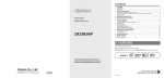
REF.10
Storage
Preparing for storage
Before you start
If repairs or an overhaul is needed, see that
this is carried out now rather than left until you
want to ride the bike again.
Give the bike a good wash and scrub all dirt
from its underside. Make sure the bike dries
completely before preparing for storage.
Engine
. Remove the spark plug(s) and lubricate the
cylinder bores with approximately a teaspoon
of motor oil using a spout-type oil can (see
Illustration
1). Reinstall the spark plug(s).
Crank the engine over a couple of times to
coat the piston rings and bores with oil. If the
bike has a kickstart. use this to tum the engine
over. If not. flick the kill switch to the OFF
position and crank the engine over on the
starter (see illustration 2). If the nature on the
ignition system prevents the starter operating
with the kill switch in the OFF position,
remove the spark plugs and fit them back in
their caps; ensure that the plugs are earthed
(grounded) against the cylinder head when the
starter is operated (see illustration 3).
Warning: It is important that the
/:\
ili
plugs are earthed (grounded)
away from the spark plug holes
otherwise there is a risk of
atomised fuel from the
cylinders igniting.
=
.
HIN
On a single cylinder four-
strokeengine,youcanseal
the combustion chamber
completelyby positioning
thepistonat roc on the compression
stroke.
Battery
. Remove
it fromthe
bike
- in extreme
cases
of cold the battery may freeze and crack its
case (see Illustration 6).
Connect a hose to the carburettor float
chamber drain stub (arrow) and unscrew
Squirt a drop of motor oil into each
cylinder
. . . and ensure
that the metal bodies of the
plugs (arrows) are earthed against the
cylinder head
the drain screw
. Drain the carburettor(s) otherwise there is a
risk of jets becoming blocked by gum
deposits from the fuel (see ilklsb'8tlon 4).
. If the bike is going into long-term storage,
consider adding a fuel stabiliser to the fuel in
the tank. If the tank Is drained completely,
corrosion of its internal surfaces may occur if
left unprotected for a long period. The tank
can be treated with a rust preventative
especially for this purpose. Alternatively,
remove the tank and pour half a litre of motor
011into it, install the filler cap and shake the
tank to coat its intemals with oil before
draining off the excess. The same effect can
also be achieved by spraying WD40 or a
similar water-dispersant around the inside of
the tank via its flexible nozzle.
. Make sure the cooling system contains the
correct mix of antifreeze. Antifreeze also
contains important corrosion inhibitors.
. The air Intakes and exhaust can be sealed
off by covering or plugging the openings.
Ensure that you do not seal in any
condensation; run the engine until it is hot.
then switch off and allow to cool. Tape a piece
of thick plastic over the silencer end(s) (see
illustration 5). Note that some advocate
pouring a tablespoon of motor oil into the
silencer(s)beforesealingthemoff.
Disconnect the negative lead (A) first,
followed by the positive lead (8)
. Checkthe electrolytelevel
and
top
up if
necessary (conventional refillable batteries).
Clean the terminals.
. Store the battery off the motorcycle and
away from any sources of fire. Position a
wooden block under the battery if it is to sit on
the ground.
. Give the battery a trickle charge for a few
hours every month (see illustration 7).
Storage
Tyres
. Place the bike on its centrestand or an
auxiliary stand which will support the
motorcycle in an upright position. Position
wood blocks underthe tyres to keepthem off
the ground and to provide insulation from
damp. If the bike is being put Into long-term
storage, ideally both tyres should be off the
ground;not only will this protectthe tyres. but
will also ensurethat no load is placed on the
steeringheador wheelbearings.
. Deflate
eachtyreby 5 to 10 psi. no more or
the beads may unseat from the rim, making
subsequent inflation difficult on tubeless
tyres.
Pivots and controls
. Lubricateall lever,pedal,standand
footrest pivot points. If grease nipples are
fitted to the rear suspension components.
apply lubricant to the pivots.
. Lubricate all control cables.
Cycle components
. Apply
a wax
protectant
to all painted and
plastic components. Wipe off any excess, but
don't polish to a shine. Where fitted, clean the
screen with soap and water.
. Coat metal parts with Vaseline (petroleum
jelly). When applying this to the fork tubes, do
REF.11
not compress the forks otherwise the seals
will rot from contact with the Vaseline.
. Apply a vinylcleanerto the seat.
Storage
ns
. Aim to store the bike in a shed or garage
which does not leakand is free from damp.
. Drape an old blanket or bedspread over
the bike to protect it from dust and direct
contact with sunlight (which will fade paint).
This also hides the bike from prying eyes.
Beware of tight-fitting plastic covers which
may allow condensationto form and settleon
the bike.
REF.12
Fault Finding
This Section provides an easy reference-guide to the more common
faults that are likely to afflict your machine. Obviously, the
opportunities are almost limitless for faults to occur as a result of
obscure failures, and to try and cover all eventualities would require a
book. Indeed, a number have been written on the subject.
Successful troubleshooting is not a mysterious 'black art' but the
application of a bit of knowledge combined with a systematic and
logical approach to the problem. Approach any troubleshooting by first
accurately identifying the symptom and then checking through the list
of possible causes, starting with the simplest or most obvious and
progressingin stagesto the most complex.
Take nothing for granted, but above all apply liberal quantities of
commonsense.
The main symptomof a fault is given in the text as a majorheading
belowwhich are listedthe varioussystemsor areaswhich maycontain
the fault. Detailsof each possiblecause for a fault and the remedial
action to be taken are given, in brief, in the paragraphsbelow each
heading.Furtherinformationshouldbe soughtin the rejevantChapter.
1 Engine doesn't start or Is difficult to start
7 Abnonnal engine noise
0
0
0
0
0
0
0
0
0
0 Knockingor pinglng
0 Pistonslap or rattling
0 Valvenoise
0 Othernoise
Startermotordoesn'trotate
Startermotorrotatesbutenginedoesnottumover
Starterworksbutenginewon'ttumover(seized)
Nofuelflow
Engine
flooded
Nosparkor weakspark
Compression
low
Stallsafterstarting
Roughidle
8 Abnonnal
driveline
0 Clutchnoise
0 Transmissionnoise
0 Finaldrivenoise
noise
2 Poor running at low speed
9 Abnormal frame and suspension noise
0
0
0
0
0
0
0
Sparkweak
Fuel/airmixtureincorrect
Compressionlow
Pooracceleration
3 Poor running or no power at high speed
0 FIringincorrect
0
0
0
0
FueValrmixtureincorrect
Compressionlow
Knockingor pinging
Miscellaneouscauses
4 Overheating
0 Engineoverheats
0 FIringIncorrect
0 FueVairmixtureJncorrect
0 ComPfMSiontoo high
p engine1089excessive0 Lubricationinadequate
0 Miscellaneouscauses
5 Clutch
:0
Q
problems
Clutch slipping
Clutch not disengaging completely
shifting problems
Doesn'tgo into gear,or leverdoesn't return
Jumpsout of gear
Overshifts
Frontend noise
Shockabsorbernoise
Brakenoise
10011pressure indicator light comes on
0
0
Enginelubricationsystem
Electricalsystem
11
0
0
0
excessive exhaust
Whitesmoke
Blacksmoke
Brownsmoke
smoke
12 Poor handling or stability
0 Handlebarhardto tum
0 Handlebarshakesor vibratesexcessively
0 Handlebarpullsto one side
0 Poorshock absorbingqualities
13
0
0
0
Braking problems
Brakesare spongy.don't hold
Brakeleveror pedalpulsates
Brakesdrag
14 Electrical problems
0 Batterydeador weak
0 Batteryovercharged
Fault Finding REF.13
1 Engine doesn't start or is difficult to start
-
Stalter
motor
doesn't
rotate
[J Startingtechniqueincorrect.UndernormalcircumstancesO.e.,if
0
0
0
Engine kill switch OFF.
Fuse blown. Check fuse (Chapter 8).
Battery voltage low. Check and recharge battery (Chapter 8).
all the carburettor functions are sound) the machine should start
with little or no throttle. When the engine is cold, the choke should
be operated a~d ~heengine started without opening the th~ttle.
0
Startermotordefective.Makesure the wiringto the starteris
secure.Makesurethe starterrelayclicks whenthe start button is
pushed.If the relayclicks,thenthe fault is in the wiringor motor.
Starterrelayfaulty.Checkit accordingto the procedurein Chapter8.
Whenthe engineISat operatingtemperature,only.a veryslight
amountof throttleshould,be n~sary. If th~ eng,".eis .flooded
hol~~hethr?ttleopenwhilecrankingthe engine.Thiswill allow
additionalair to reachthe cytind9'S.
0
Starterswitch not contacting.The contactscould bewet,
or dirty. Disassembleand ~~eanthe switch(Chapt~ 8),
0 Wiringopen or shorted.Checkall WIringconnectionsand
harnesses
sure
they
are dry,
and not
corroded.
Also
checkto
formake
broken
orttlat
frayed
wires
thattight
can cause
a short
to
ground(earth)(seewiring diagram,Chapt~ 8),
0 Ignition(main)switchdefective.Checkthe switchaccordingto the
procedurein Chapter8. Replacethe switchwith a newone if it is
defecti
0 EngineV~il
switchdefective.Checkfor wet, dirty or corroded
contacts.Cleanor replacethe switchas necessary(Ch ter 8).
.
,ap
0
co:~
,
0
0
No spark or weak spark
0
0
0
ap er .
Sparkpl~gsdirty, defective~ worn out, Locatereasonfor fouled
plugsuSIngsparkplug conditIonchart and follow the plug
maintenanceprocedures(Chapter1).
0 Sparkpl~ caps or secondary(HT)":firingfaulty.C~k ~Ition.
R~placeeitheror both componentsIf cracksat detenoratlOO
are
evident(Chapter4).
Faulty neutral
side stand
switch. Check
theprocedures
wiring to each
0 Sp
kitp ugficaps
l
codntact . Make suret hat the
t
nly
switch
and theorswitch
itself according
to the
in
,..j ar
° makJthng good
Chapter8.
~u~.caps I snug, over .epugen s'.
.
Faultysidestandrelayor diode,Checkaccordingto the procedure 0 Ignition~ntrol Unitdefective.Checkttle Unit,refemngto Chapter
,
Ch t 8
4 for details.
In ap er .
0 Pulsegeneratorcoils defective.Checkthe coils, referringto
0
Statter motor rotates but engine does not turn over
0
0
Starterclutch defective.Inspectand repairor replace(Chapter2).
Damagedidle/reductiongearor startergears.Inspectand replace
the damagedparts (Chapter2),
Starter works but engine won't turn over (seized)
0 Seizedenginecausedby one or moreinternallydamaged
components.Failuredue to wear,abuseor lack of lubrication,
Damagecan includeseizedvalves, followers,camshafts,pistons,
crankshaft,connectingrod bearings,or transmissiongearsor
bearings.Referto Chapter2 for enginedisassembly,
No fuel flow
0 No,fuelin tank,
0 Mainfuel cock filter clogged.Removethe fuel cock and cleanit
and the filter (Chapter3).
0 Fuellineclogged.Pullthe fuel line looseand carefullyblow
ttlroughit.
0 Floatneedlevalveclogged.For both of the valvesto be clogged,
eithera verybad batch of fuel with an unusuaJadditivehas been
used,or someotherforeignmaterialhasenteredthe tank. Many
timesafter a machinehas beenstoredfor manymonthswithout
running,the fuel turns to a varnish-likeliquidand formsdeposits
on the Inletneedlevalvesand jets. Thecarburettorsshould be
removedand overhauledif draJningthe float chambersdoesn't
solvethe problem(Chapter3).
Engln
flooded
e
0
0
IgnitionswitchOFF.
E ' k' il ' t h t ed t th OFF it,
nglne
I SWI C
urn
0
e
pos Ion.
Batterr v~)Itage 10w. Check and rechargethe battery as necessary
(Ch
Chapter
4 fordetails.
0
IgnitionHTcoils defective.Checkthe coils, referringto Chapter4
for detaJls.
0 Ignitionor kill switchshorted.This is usuallycausedby wat~,
corrosion,damageor excessivewear.The switchescan be
disassembledand cleanedwith electricalcontactcleaner.If
cl~ning doesnot help,replacethe switches(Chapter8).
0 Wlnngshortedor brokenbetween:
a) Ignition(main)switchand enginekill switch (or blown fuse)
b) Ignitioncontrolunit and enginekill switch
c) Ignitioncontrolunit and ignitionHT coils
d) IgnitionHT coilsand Sparlcplugs
e) Ignitioncontrolunit andpulsegeneratorcoils
0 Makesurethat all wiringconnectionsare clean,dry and tight.
Lookfor chafedand brokenwk'es(Chapters4 and 8).
.
CompressIon low
[]
0
0
0
Sparkplugsloose.Removethe plugsand inspecttheir threads.
Reinstalland tightento ttle specifiedtorque(Chapter1).
Cylinderheadnot sufficientlytighteneddown. If the cylinderhead
is suspectedof beingloose,then there'sa chancethat the gasket
or headis damagedif the problemhas persistedfor any lengthof
time.The headbolts shouldbe tightenedto the propertorquein
the correctsequence(Chapter2).
Impropervalveclearance.This meansthat the valveis not closing
completelyand compressionpressureis leakingpast the valve.
Checkand adjustthe valveclearances(Chapter1).
Cylinderand/orpistonworn. Excessivewearwill cause
Float height incorrect. Check and adjust as necessary (Chapter 3).
Float needle valve worn or stuck open. A piece of dirt, rust or other
compression pressure to leak past the rings. This is usually
debriscan causethe valveto seatimproperly, causingexcessfuel
necessary(Chapt~ 2).
to be admitted to the float chamber. In this case, the float chamber
accompanied
0
by worn rings as well. A top-end
overhaul is
Piston rings worn, weak, broken, or sticking. Brok«1 or sticking
shouldbe cleanedand the needlevalveand seat inspected.If the
piston ringsusuallyindicatea lubricationor CBl'buration
problem
needle and seat are worn, then the leaking will persist and the parts
that causes excess carbon deposits
shouldbe replacedwith newones(Chapter3).
pistons and rings. Top-endoverhaulis necessary(Chapter2).
or seizures to form on the
Fault Finding
1 Engine doesn't start or is difficult to start (continued)
REF.14
0
Pistonring-to-grooveclewanceexcessive.Thisis causedby
excessivewearof the pistonring lands.Pistonreplacementis
necessary(Chapter2).
0 Cylind« headgasketdamaged.If the headis allowedto become
loose,or if excessivecarbonbuild-upon the pistoncrownand
combustionchambercausesextremelyhigh compression,the
headgasketmay leak.Retorquingthe headis not always
sufficientto restorethe seal,so gasketreplacementis necessary
(Chapter2).
0 Cylinderheadwarped.This is causedby ovett1eating
or
improperlytightenedheadbolts. Machineshop resurfacingor
headreplacementis necessary(Chapter2).
0 Valvespringbrokenor weak.Causedby componentfailureor
wear;the springsmust be replaced(Chapter2).
0 Valvenot seatingproperly.Thisis causedby a bent valve(from
over-rewingor impropervalveadjustment),bumedvalveor seat
(impropercarburation)or an accumulationof carbondepositson
the seat (fromcarburationor lubricationproblems).Thevalves
must be cleanedand/orreplacedand the seatsservicedif
possible(Chapter2).
Stalls after starting
0
0
Improper choke action. Make sure the choke linkage shaft is
getting a full stroke and staying in the out position (Chapter 3).
Ignition malfunction (Chapter 4).
e Carburettormalfunction(Chapter3).
a Fuelcontaminated.Thefuel can be contaminatedwith eitherdirt
or water,or can changechemicallyif the machineIs allowedto sit
for severalmonthsor more.Drainthe tank and float cham~
(Chapter3).
0 Intakeair leak.Checkfor loosecarburettor-to-intakemanifold
connections,looseor missingvacuumgaugeadaptercaps,or
loosecarburettortops (Chapter3).
Engineidle speedincorrect.Turn idle adjustingscrew until the
engineidlesat the specifiedrpm (Chapter1).
Rough Idle
0
0
0
0
Ignitionmalfunction(Chapter4).
Idlespeedincorrect(Chapter1).
Carburettorsnot synchronlsed.Adjustcarburettorswith vacuum
gaugeor manometerset (Chapter1).
0 Carburettormalfunction(Chapter3).
0 Fuelcontaminated.The fuel can be contaminatedwith eitherdirt
or water,or can changechemicallyif the machineis allowedto sit
for severalmonthsor more.Drainthe tank and float chambers
(Chapter3).
0 Intake air leak. Check for loosecarburettor-to-intake manifold
connections,loose or missingvacuumgaugeadaptercaps, or
0
loose carburettor tops (Chapter 3).
Air filter clogged. Replace the air filter element (Chapter 1).
2 Poor running at low speeds
Battery voltage low. Check and recharge battery (Chapter 8).
Spark plugs fouled, defective or worn out (Chapter 1)
Spark plug cap or HT wiring defective (Chapters 1 and 4).
Spark plug caps not making contact. Make sure they are properly
connected.
Incorrect spark plugs. Wrong type, heat range or cap
configuration. Check and install correct plugs (Chapter 1).
Ignition control defective (Chapter 4).
Pulse generator coils defective (Chapter 4).
Ignition HT coils defective (Chapter 4).
Fuel/air mixture incorrect
a
Pilot screws out of adjustment (Chapter 3).
Pilot jet or air passage clogged. Remove and overhaul the
carburettors (Chapter 3).
Air bleed holes clogged. Remove carburettor and blow out all
passages (Chapter 3).
Air filter clogged, poorly sealed or missing (Chapter 1).
Air filter housing poorly sealed. Look for cracks, holes or loose
clamps and replace or repair defective parts (Chapter 3).
Fuel level too high or too low. Check the float height (Chapter 3).
Carburettor intake manifolds loose. Check for cracks, breaks,
tears or loose clamps. Replace the rubber intake manifold joints if
split or perished (Chapter 3).
Compression low
0
0
Spark plugs loose. Remove the plugs and inspect their threads.
Reinstall and tighten to the specified torque (Chapter 1).
Cylinder head not sufficiently tightened down. If the cylinder head
is suspected of being loose, then there's a chance that the gasket
or head is damaged if the problem has persisted for any length of
time. The head boits should be tightened to the proper torque in
the correct sequence (Chapter 2).
0
Improper valve clearance. This means that the valve Is not closing
completely and compression pressure Is leaking past the valve.
Check and adjust the valve clearances (Chapter 1).
0
Cytinder and/or piston worn. Excessive wear will cause
compression pressure to leak past the rings. This Is usually
accompanied by worn rings as well. A top-end overhaul is
necessary (Chapter 2).
0
Piston rings wom, weak, broken, or sticking. Broken or sticking
piston rings usually indicate a lubrication or carburation problem
that causes excess carbon deposits or seizures to form on the
pistons and rings. Top-end overhaul is necessary (Chapter 2).
0
Piston rlng-to-groove clearance excessive. This is caused by
excessive wear of the piston ring lands. Piston replacement Is
necessary (Chapter 2).
0
Cytinder head gasket damaged. If the head is allowed to become
loose, or if excessive carbon build-up on the piston crown and
combustion chamber causes extremely high compression, the
head gasket may leak. Retorquing the head is not always
sufficient to restore the seal. so gasket replacement is neOe68ary
(Chapter 2).
Cylinder head warped. This Is caused by overheating or
improperly tightened head bolts. Machine shop resurfacing or
head replacement is necessary (Chapter 2).
0
0
Valve spring broken or weak. Caused by component failure or
wear; the springs must be replaced (Chapter 2).
0
Valve not seating PfOPefiy.This Is caused by a bent valve (from
over-revving or improper valve adjustment). burned valve or seat
(Improper carburation) or an accumulation of carbon deposita on
the seat (from carbu~ion or lubrication problems). The valves
must be cleaned and/or replaced and the seats serviced if
possible (Chapter 2).
Fault Finding
REF-15
2 Poor running- at low speeds (continued)
Poor acceleration
0
Engineoil viscositytoo high. Usinga heavier oil than that
recommended in Chapter 1 can damage the 011pump or
0
0
0
Carburettors leakingor dirty. Overhaulthe carburettors(Chapter3).
Timingnot advancing.Faultypick-upcoils or ignitOf'unit(Chapter4).
Cartxnttors not synchronised.Adjustthem with a vacuum gauge
0
set or manometer(Chapter1).
lubricationsystemand causedrag on the engine.
Brakesdragging.UsuaHycausedby debriswhich hasenteredthe
brakepistonseals,or from a warpeddisc or bent axle.Repairas
necessary(Chapter6).
3 Poor running or no power at high speed
-
FIring incorrect
0 Air filter restricted.Cleanor replacefilter (Chapter1).
0 Sparkplugsfouled,defectiveor worn out (Chapter1).
0 Sparkplug cap or HT wiringdefective(Chapters1 and 4).
0 Spark lug caps not makingcontact.Makesurethey are property
con~ed
0
Incon'ect spark plugs. Wrong type, heat range or cap
configuration. Check and install correct plugs (Chapter 1).
0
0
0
Ignitioncontrol unit defective(Chapter4).
Pulsegeneratorcoils defective(Chapter4).
IgnitionHTcoils defective(Chapter4).
FueValr mixture Incorrect
0 Air bleedholesclogged.Removecarburettorand blow out all
passages(Chapter3).
0 Air filter clogged,poorlysealedor missing(Chapter1).
0 Air filter housingpoor1ysealed.Lookfor cracks,holesor loose
clampsand replaceor repairdefectiveparts(Chapter3),
0 Fueileveltoo high or too low. Checkthe float height(Chapter3).
0 Carburettorintakemanifoldsloose.Checkfor cracks,breaks,
tearsor looseclamps.Replacethe rubberintakemanifoldjoints if
split or perished(Chapter3),
0 Jet needleincorrectlypositionedor wom Checkand adjustor
replace(Chapter3).
0 Mainjet clogged.Dirt, wateror other contaminantscan clog the
mainjets, Cleanthe fuel tap filter, the in-linefilter, the float
chamberarea,and the jets and carburettororifices(Chapter3).
D Mainjet wrong size.The standardjetting is for sealevel
atmosphericpressureand oxygencontent.Checkjet size
(Chapter3).
0 Throttleshaft-to-carburettorbody clearanceexcessive.Overhaul
carburettors,reJ)iacingworn parts or completecarburettorif
necessary(Chapter3),
.
CompressIon
/ow
0 Sparkplugs loose,Removethe plugs and inspecttheir threads.
Reinstall
andtightento thespecified
torque(Chapter
1).
0
Cylinderheadnot sufficientlytighteneddown. If the cylinderhead
is suspectedof being loose,then there'sa chancethat the gasket
or head is damaged if the problem has persisted for any length of
time.The headbolts shookibe tightenedto the propertorquein
the correctsequence(Chapter2).
D Impropervalveclearance.This meansthat the valveis not closing
completelyand compressionpressureis leakingpastthe valve.
Checkandadjustthevalveclearances
(Chapter
1).
0
Cytinderand/or pistonwom. Excessivewearwill cause
compressionpressureto leak past the rings.Thisis usually
accompaniedby wom ringsas well. A top-endoverhaulis
necessary(Chapter2).
0 Pistonringswom,weak,broken,or sticking.Brokenor sticking
piston ringsusuallyindicatea lubricationor carburationproblem
that causesexcesscarbondepositsor seizuresto form on the
pistonsand rings.Top-endoverhaulis necessary(Chapter2).
0
0
Pistonring-to-grooveclearanceexcessive.Thisis causedby
excessivewearof the pistonring lands.PIstonreplacementis
nec:essary
(Chapter2).
Cylinderhead~et damaged"Ifthe headis ~Iowedto become
loose,or.if excessIVe
carbonbuild-upon ~hepistonCfO';Nn
and
combustionchambercausesextremelyhigh compresSIon,
the
head .gasket may leak. Retorquing the head is not al~ays
sufficient to restore the seal, so gasket replacement IS necessary
(Ch.apter
2).
,
Cytlnderheadwarped.This IScausedby overheatingor
improperlytightenedheadbolts. Machineshop resurfacingor
headreplacementis necessary(Chapter2).
0 Valvespringbrokenor weak.Causedby componentfailureor
wear;the springsmustbe replaced(Chapter2).
0 Valvenot seatingproperly.This is causedby a bent valve(from
over-rewingor impropervalveadjustment),burnedvalveor seat
Qmpropercarburation)or an accumulationof carbondepositson
the seat(fromcarburationor lubricationproblems).Thevalves
must be cleanedand/orreplacedand the seatsservicedif
possible(Chapter2).
0
Knocklng
or plnglng
0
Carbonbuild-upin combustionchamber.Use of a fuel additive
that will dissolvethe adhesivebondingthe carbonparticlesto the
crownand chamberis the easiestway to removethe build-up.
Otherwise,the cylinderheadwill haveto be removedand
decarbonized(Chapter2).
0 Incorrector poor qualityfuel. Old or impropergradesof fuel can
causedetonation.Thiscausesthe pistonto rattle,thus the
knockingor pinglngsound.Drainold fuel and alwaysusethe
recommendedfuel grade(Chapter3).
0 Sparkplug heatrangeincorrect.Uncontrolleddetonationindicates
the plug heatrangeis too hot. The plug in effect becomesa glow
plug,raisingcylindertemperatures.Installthe properheatrange
plug (Chapter1).
0 Improperair/fuelmixture.Thiswillcausethecylinderto runhot,
which leadsto detonation.Cloggedjets or an air leakcan cause
this imbalance(Chapter3).
..,
...,sce " ,aneous causes
0 Throttlevalvedoesn't openfully. Adjustthe throttlegrip freeplay
(Chapter1).
0 Clutchslipping.May be caused
by looseor wom clutch
components.Overhaulclutch (Chapter2).
0 Timingnot advancing.Ignitioncontrol unit faulty (Chapter4).
D Engineoil viscositytoo high. Usinga heavier011
than the one
recommendedin Chapter1 can damagethe oil pump or
lubrication
systemandcausedragontheengine.
0 Brakesdragging.Usuallycausedby debriswhich has enteredthe
brakepistonseals,or from a warpeddisc or bentaxle.Repairas
necessary.
REF.16 F au It
Finding
4 Overheating
FIring Incorrect
0 Engineoil leveltoo high.The additionof too muchoil will cause
0 Spar1<
plugsfouled,defectiveor wom out (Chapter1).
pressurisationof the crankcaseand inefficientengineoperation.
0 Incorrectspar1<
plugs(Chapter1).
CheckSpecificationsand drainto properlevel(Chapter1).
0 FaultyignitionHTcoils (Chapter4).
0 Engineoil viscositytoo high.Usinga heavieroil than the one
.
recommendedin Chapter1 can damagethe oil pump or
Fuel/air mixture Incorrect
lubricationsystemas well as causedrag on the engine.
0 Mainjet clogged.Dirt,waterand othercontaminantscan clog the
0 Brakesdragging.Usuallycausedby debriswhich hasenteredthe
mainjets. Cleanthe fuel tap filter.the fuel pumpin-linefilter,the
brakepistonseals,or from a warpeddisc or bentaxle. Repairas
float chamberareaand the jets and carburettororifices(Chapter3).
necessary.
D Mainjet wroogsize.The standardjetting is for sea level
D Excessivefriction in movingengineparts due to inadequate
atmosphericpressureand oxygencontent.Checkjet size
lubrication,wom bearingsor incorrectassembly.Overhaulengine
(Chapter3).
(Chapter2).
D Air filter clogged,POOI1Y
sealedor missing(Chapter1).
D Air filter housingpoorlysealed.Look for cracks,holesor loose
Lubrication
inadequate
clampsand replaceor repair(Chapter3).
!:J Engineoil leveltoo low. Frictioncausedby intennittentlack of
D Fuelleveltoo low. Checkfloat height(Chapter3).
lubricationor from oil that is overworkedcan causeoverheating.
D Carburettorintakemanifoldsloose.Checkfor cracks,breaks,
Theoil providesa definitecoolingfunctionin the engine.Check
tearsor looseclamps.Replacethe rubberintakemanifoldjoints if
the oil level(Chapter1).
split or perished(Chapter3).
D PoorqualityengIne011
or incorrectviscosityor type. 011is rated
Compression
."
D
Carbo~
that
piston
too high
b~lld-up
WIll dissolve
crown
and
In combu~tlon
the adhesive
chamber
is
cha~ber.
bonding
the
.
Use of a fuel ,additive
the carbon
easiest
way
to
particles
remove
the
to the
,~
bUlld-
up. Otherwise,the cylinderheadwill haveto be removedand
decarbonized(C~apter2).
,
,
D Improperlymachinedheadsurfaceor Installationof InCOrrect
gasketduringengineassembly(Chapter2),
Engine
0
not only accordingto viscositybut also accordingto type. Some
oils are not ratedhigh enoughfor use in this engine.Checkthe
,.
load excessive
Specifications
0 Wom
01 '
section
I pump
or
(Ch
t
c
and change
logged01 ' I
to the correct
passages.
Check
011 (Chapter
01 . 1 pump
an
1).
d
cI ean
2)
passages ap er .
Miscellaneous
causes
0
0
Clutch slipping. Can be caused by damaged, loose or worn clutch
components. Overhaul clutch (Chapter 2).
Enginecoolingfins cloggedwith debris.
Modificationto exhaustsystem.Most aftermarketexhaust
systemscausethe engineto run leaner,which makethem run
hotter. When installing an accessory exhaust system, always rejet
the carburettors.
5 Clutch problems
Clutch slipping
0
0
Cablefreeplayinsufficient.Checkand adjustcable(Chapt«1).
Frictionplateswom or warped.Overhaulthe clutch assembly
(Chapter2).
0 Plainplateswarped(Chapter2).
0 Clutchspringsbrokenor weak.Old or heat-damaged(from
slippingclutch)springsshouldbe replacedwith new ones
(Chapter2).
0 Clutchreleasemechanismdefective.Replaceany defectiveparts
(Chapter2).
0 Clutchcentreor housingunevenlyworn. Thiscausesimproper
engagementof the plates.Replacethe damagedor wom parts
(Chapt«2).
Clutch not disengaging completely
0
0
Cablefreeplayexcessive.Checkand adjustcable(Chapter1).
Clutchplateswarpedor damaged.This will causeclutch drag,
which in turn will causethe machineto creep.Overhaulthe clutch
assembly(Chapter2).
Clutch spring tension uneven. Usually caused by a sagged or
broken spring. Check and replace the springs as a set (Chapter 2).
011deteriorated. Old. thin, worn out 011will not provide
PrEngine
proper lubrication for the plates. causing the clutch to drag.
Replace the 011and filter (Chapter 1).
Q!
0
Engine oil viscosity too high. Using a heavier oil than
recommended In Chapter 1 can cause the plates to stick together,
putting a drag on the engine. Change to the correct weight oil
(Chapter 1).
Clutch housing seized on mainshaft. Lack of lubrication, severe
wear or damage can cause the guide to seize on the shaft.
Overhaul of the clutch. and perhaps transmission. may be
necessary to repair the damage (Chapter 2).
release mechanism defective. Overhaul the clutch cover
~ Clutch
components (Chapter 2).
~
~:
Loose clutch centre nut. Causes drum and centre misalignment
putting a drag on the engine. Engagement adjustment continually
varies. Overhaul the clutch assembly (Chapter 2).
Fault Finding
REF.17
6 Gear shifting problems
Doesn't go Into gear or 'ever doesn't return
0
0
0
0
Clutchnot disengaging.Seeabove.
Selectorfork(s)bent or seized.Oftencausedby droppingthe
machineor from lack of oil. Overhaulthe transmission(Chapter2).
0 ~s)
stuck on shaft. Most often causedby a lack of lubrication
or excessivewearIn transmissionbearingsand bushings.
OveIt1aul
the transmission(Chapter2).
0 Gearselectordrum binding.Causedby lubricationfailureor
excessivewear.Replacethe drum and bearing(Chapter2).
0 Gearcnangeleverreturnspringweakor broken(Chapter2).
0 Gearchangeleverbroken.Splinesstrippedout of leveror shaft,
causedby allowingthe leverto get !<Jose
or from droppingthe
machine.Replacenecessaryparts(Chapter2).
Gearchangemechanismstopperarm brokenor wom. Full
engagementand rotarymovementof shift drum results.Replace
the arm (Chapter2).
Stopperarm springbroken.Allowsarm to float, causingsporadic
shift operation.Replacespring(Chapter2).
Jumps out of gee'
0
0
0
Selector fork(S)worn. Overhaul the transmission (Chapter 2).
Gear groove(s) worn. Oveft)aul the transmission (Chapter 2).
Gear dogs or dog slots worn or damaged. The gears should be
inspected and replaced. Don't service the wom parts (Chapter 2).
Overshlfts
0 Stopperarm springweakor broken(Chapter2).
0 Gearchange
shaftretumspringpost brokenor distorted(Chapter2).
7 Abnormal engine noise
Knocking or plnglng
0 Carbonbuild-upin combustionchamber.Useof a fuel additive
that will dissolvethe adhesivebondingthe carbonparticlesto the
pistoncrown and chamberis the easiestway to removethe buildup. Otherwise,the cylinderheadwill haveto be removedand
decarbonized(Chapter2).
0 Incorrector poor qualityfuel. Old or improperfuel can cause
detonation.This causesthe pistonsto rattle,thus the knockingor
pingingsound. Drainthe old fuel and alwaysusethe
recommendedgradefuel (Chapter3).
0 Sparkplug heatrangeincorrect.Uncontrolleddetonationindicates
that the plug heatrangeis too hot. The plug in effect becomesa
glow plug, raisingcylindertemperatures.Installthe properheat
rangeplug (Chapter1).
0 Improperair/fuelmixture.This will causethe cylindersto run hot
and leadto detonation.Cloggedjets or an air leakcan causethis
imbalance(Chapter3).
PIston slap or rattling
.,
.
.
0 Cyllnder-to-plstonclearanceexcesSIve.Causedby Improper
Inspect
andCaused
overhaul
parts (Chapter
2). a
0 assembly.
Connecting
rod bent.
bytop-end
over-rewing,
tryingto start
0
badly flooded engine or from ingesting a foreign object into the
combustion chamber. Replace the damaged parts (Chapter 2).
0
Pistonpin or piston pin boreworn or seizedfrom wearor lack of
lubrication.Replacedamagedparts (Chapter2).
Pistonring(s)worn, brokenor sticking.Overhaulthe top-end
(Chapter2).
Pistonseizuredamage.Usuallyfrom lack of lubricationor
overheating.Replacethe pistonsand borethe cylinders,as
necessary(Chapter2).
failure.Canalso be attnbutedto droppingthe machIneon eitherof
the crankshaftends(Chapter2).
0 Enginemountingbolts loose.TIghtenall enginemountbolts
(Chapter2).
0 Crankshaftbearingsworn (Chapter2).
0 Camchaintenslonerdefective.Replace(Chapter2).
0 Camchain,sprocketsor guidesworn (Chapter2).
0
0
0
Connectingrod upperor lowerend clearanceexcessive.Caused
by excessiveweeror lack of lubrication.Replaceworn parts
(Chapter2).
Valve noIse
0
0
0
Incorrectvalveclearances.Adjustthe clearances(Chapter1).
Valvespringbrokenor weak.Checkand replaceweakvalve
springs(Chapter2).
Camshaftor cylinderheadworn or damaged.Lackof lubrication
at high rpm is usuallythe causeof damage.Insufficientoil or
failureto changethe oil at the recommendedintervalsarethe
chief causes.Sincethereare no replaceablebearingsin the head,
the headitselfwill haveto be replacedif thereis excessivewear
or damage(Chapter2).
.
Other noIse
0 Cylinderheadgasketleaking(Chapter1).
0 Exhaustpipe leakingat cylinderheadconnection.Causedby
improperfit of pipe(s)or looseexhaustflange.Ail exhaust
fastenersshouldbe tightenedevenlyand carefully.Failureto do
tho
t 3)
ISWI'ill ead t0 a Ieak (Cha
. per.
Cranksha~ runout excessIVe. Caused by a bent crankshaft (from
o~er-rewlng) or damag~ from an upper cylinder co~ponent
Fault Finding
9 Abnormal frame and suspension noise
REF.18
Front end noise
0
Low fluid level
or improper viscosity oil in forks. This can sound
like spurting and Is usually accompanied by irregular fork action
0
0
0
0
0
(Chapter 5).
Springweakor broken.Makesa clicking or scrapingsound.Fork
oil, when drained, will have a lot of metal particlesin it (Chapter5).
Steeringheadbearingslooseor damaged.Clickswhenbraking.
Check and adjust or replaceas necessary(Chapters1 and 5).
Fork yokes loose. Make sure all clamp pinch bolts are tight
(Chapter 5).
Fork tube bent. Good possibility if machine has been dropped.
Replace tube with a new one (Chapter 5).
Front axle or axle clamp bolt loose. Tighten them to the specified
torque (Chapter 6).
Shock absorber noise
0
0
Fluid level incorrect. Indicates a leak caused by defective seal.
Shock will be covered with oil. Replace shock or seek advice on
repair from a Suzuki dealer (Chapter 5).
Defective shock absorber with internal damage. This is in the body
of the shock and can't be remedied. The shock must be replaced
0
0
Bent or damaged shock body. Replace the shock with a new one
(Chapter 5).
Loose or wom linkage components. Check and replace as needed
(Chapter 5).
Brake noise
0
Squealcausedby pad shim not installedor positionedcorrectly
(Chapter6).
0 Squealcausedby dust on brakepads.UsuallyfoundIn oomt*'lation
with glazedpads.CleanuU1gbrakecleaningsolvent(Chapt«6).
0 Contaminationof brakepads.011,brakefluid or dirt causingbrake
to chatteror squeal.Cleanor replacepads (Chapter6).
0 Padsglazed.Causedby excessiveheatfrom prolongeduseor
from contamination.Do not use sandpaper.emerycloth,
carborundumcloth or any other abrasiveto roughenthe pad
surfacesas abrasiveswill stay in the pad materialand damagethe
disc. A veryfine flat file can be used.but pad replacementis
suggestedas a cure (Chapter6).
0 Discwarped.Cancausea chattering,clickingor int~ittent
squeal.Usuallyaccompaniedby a pulsatingleverand uneven
braking.Replacethe disc (Chapter6).
0 Looseor wom wheelbearings.Checkand replaceas needed
with a new one (Chapter 5).
(Chapter 6).
10 Oil pressure light comes on
EngIne lubrication system
0
0
0
0
Engineoil pump defective,blockedoil strainergauze or failed
relief valve.Carryout oil pressurecheck(Chapter2).
Engine oil level low. Inspect for leak or otherproblemcausinglow
oil leveland add recommendedoil (Chapter1).
Engine oil viscosity too low. Very old, thin oil or an improper
weightof oil used in the engine. Changeto correctoil (Chapter1).
Camshaftor journalsworn. Excessivewearcausingdrop in oil
0
Crankshaftand/orbearingsworn. Sameproblemsas parawaph4.
Checkand replacecrankshaftand/orbearings(Chapter2).
Electrical
system
0 Oil pressureswitchdefective.Checkthe switchaccordingto the
procedurein Chapter8. Replaceit if it is defective.
0 Oil pressureindicatorlight circuit defective.Checkfor pinched,
shorted,disconnectedor damagedwiring(Chaptw8).
pressure. Replace cam and/or/cylinder
head. Abnormal wear
could be caused by oil starvation at high rpm from low oil level or
improper weight or type of oil (Chapter 1).
11 Excessive exhaust smoke
White smoke
0
Pistonoil ring worn.The ring maybe brokenor diM11aged,
causing
oil from the crankcaseto be pulledpast the pistonIntothe
combustionchamber.Replacethe ringswith newones(Chapter2).
0 Cylindersworn, cracked,or scored.Causedby overheatingor oil
starvation.The cylinderswill haveto be reboredand new pistons
installed(Chapter2).
0 Valveoil sealdamagedor worn. Replaceoil sealswith new ones
(Chapter2).
0 Valveguideworn. Performa completevalvejob (Chapter2).
0 Engine011
leveltoo high,whichcausesthe oil to be forcedpast
0
0
a~ Main jet too large CM'~.
"\..a:
Q!
Q
Brown smoke
the rings. Drain 011to the proper level (Chapter 1).
0
Headgasketbrokenbetween011returnand cylinder.Causesoil to
be pulledinto the combustionchamber.Replacethe heedgasket
and checkthe headfor warpage(Chapter2).
Abnormalcrankcasepressurisation,whichforcesoil past the
rings.Cloggedventilationsystemor breatherhose(Chapte.2).
0
Black smoke
0 Airfilterclogged.Cleanor replacetheelement
(Chapter
1).
Compare jet size with the Specifications
(Chapter 3).
Choke cable or linkage shaft stuck, causing fuel to be pulled
through choke circuit (Chapter 3).
Fuel level too high. Check and adjust the float height(s) as
necessary (Chapter 3).
Float needle valve held off needle seat. Clean the float chambers
and fuel line and replace the needles and seats if necessary
(Chapter 3).
0
0
Main jet too small or clogged. lean condition caused by wrong
size main jet or by a restricted orifice. Clean float chambers and
jets and compare jet size to Specifications (Chapter 3).
Fuel flow insufficient. Float needle valve stuck closed due to
chemical reaction with old fuel. Aoat height Incorrect. Restricted
rue/line.Cleanline and float chamberand adjustfloats if
necessary (Chapter 3).
Carburettor intake manifoldclampsloose(Chapter3).
AIr fIlterpoorty sealed or not instaHed(Chapter 1).
Fault Finding
12 Poor handling- or stability
-
Handlebar hard to turn
Handlebar pulls to one side
D
0
Steering head bearing adjuster nut too tight. Check adjustment
(Chapter 1).
D Bearingsdamaged.Roughnesscan be felt as the barsaretumed
from side-to-side.Replacebearingsand races(Chapter5).
0 Racesdentedor worn. Dentingresultsfrom wearin only one
position(e.g.,straightahead),from a collisionor hittinga pothole
or from droppingthe machine.Replaceracesand bearings
(Chapter5).
0 Steeringstem lubricationinadequate.Causesare greasegetting
hardfrom age or beingwashedout by high pressurecar washes.
Disassemblesteeringheadand repackbearings(Chapter5).
0 Steeringstem bent. Causedby a collision,hittinga potholeor by
droppingthe machine.Replacedamagedpart. Don't try to
straightenthe steeringstem (Chapter5).
0 Fronttireairpressure
toolow(Chapter
1).
Handlebar shakes or vIbrates excessively
0
0
0
0
REF-19
Tyresworn or out of balance(Chapter6).
Swlngarmbearingsworn. Replaceworn bearings(Chapter5).
Rim(s)warpedor damaged.Inspectwheelsfor runout(Chapter6).
Wheelbearingsworn. Wornfront or rearwheelbearingscan
causepoor tracking.Wornfront bearingswill causewobble
(Chapter6).
0 Handlebarclamp bolts loose(Chapter5).
0 Forkyoke bolts loose.Tightenthem to the specifiedtorque
(Chapter5).
0 Enginemountingbolts loose.Will causeexcessivevibrationwith
Increasedenginerprn (Chapter2).
Frame bent. Definitely suspect this If the machine has been
dropped. Mayor may not be accompanied by cracking near the
bend.Replacethe frame(Chapter5).
[J Wheelsout of alignment.Causedby improperlocationof axle
spacersor from bent steeringstem or frame(Chapter5).
0 Swingannbent or twisted.Causedby age (metalfatigue)or
impactdamage.Replacethe arm (Chapter5).
0 Steeringstem bent. Causedby impactdamageor by droppingthe
motorcycle.Replacethe steeringstem (Chapter5).
0 Fori<tube bent. Disassemblethe forks and replacethe damaged
parts(Chapter5).
D Fori<oil leveluneven.Checkand add or drainas necessary
(Chapter5).
.
..
Poor shock absorbIng qualitIes
0 Toohard:
a} FOI1coil level excessi~ (Chapter 5).
b) Fork 01/viscosity too high. Use 8 lighter oil (see the Specifications
in Chapter 5).
c) Fork tube bent. Causes 8 harsh. sticking feeling (Chapl&r 5).
d) Shock shaft or body bent or damaged (Chapter 5).
e) Fork internal damage (Chapter 5).
f) Shock Internal damage.
g) TIre pressure too high (Chapler 1).
0 Too soft:
a) FOI1cor shock oil insufficient and/or leaking (Chapter 5).
b) Fork oil level too low (Chapter 5).
c) FOI1coil viscosity too light (Chapter 5).
d) Fork springs weak or broken (Chapter 5).
e) Shockintemafdamageor leakage(Chapter5).
REF.20
Fault Finding
14 Electrical problems
Battery dead or weak
0
0
0
0
0
0
Batteryfaulty.Causedby sulphatedplateswhich are shorted
throughsedimentation.Also. brokenbatteryterminalmakingonly
occasionalcontact(Chapter8).
Batterycablesmakingpoor contact(Chapter1).
Loadexcessive.Causedby additionof highwattagelightsor
otherelectricalaccessories.
Ignition(main)switchdefective.Switcheithergrounds(earths)
internallyor failsto shutoff system.Replacethe switch(Chapter8).
Regulator/rectifier
defective(Chapter8).
Alternatorstatorcoil open or shorted(Chapter8).
Wiring faulty. Wiring grounded (earthed) or connections loose in
ignition, charging or lighting circuits (Chapter 8).
Battery overcharged
0
Regulator/rectifier
defective.Overchargingis noticedwhenbattery
gets excessivelywarm(Chapter8).
D Batterydefective.Replacebatterywith a new one (Chapter8).
D Batteryamperagetoo low, wrongtype or size.Install
manufacturer'sspecifiedamp-hourbatteryto handlecharging
load (Chapter8).
Fault Finding Equipment
Checking engine compression
.
Low compression will result in exhaust
smoke, heavy 011consumption, poor starting
and poor performance. A compression test
will provide useful information about an
engine's condition and if performed regularly,
can give warning of trouble before any other
symptoms become apparent.
. A compression gauge will be required,
along with an adapter to suit the spark plug
hole thread size. Note that the screw-in type
gauge/adapter set up is preferable to the
rubber cone type.
. Beforecarryingout the test, first checkthe
valveclearancesas describedin Chapter1.
1 Run the engine until it reaches normal
operating temperature, then stop it and
removethe spark plug(s),taking care not to
scaldyour handson the hot components.
2 Installthe gaugeadapterand compression
gauge in No; 1 cylinderspark plug hole (...
illustration 1).
3 On kickstart-equippedmotorcycles,make
sure the ignitionswitch is OFF,then open the
throttlefully and kick the engineover a couple
of timesuntil the gaugereadingstabilises.
4 On motorcycleswith electricstart only, the
procedurewill differ dependingon the nature
of the ignition system. Flick the engine kill
switch (enginestop switch) to OFF and turn
Fault Finding Equipment
the ignition switch ON; open the throttle fully
and crank the engine over on the starter motor
for a couple of revolutions until the gauge
reading stabilises. If the starter will not operate
with the kill switch OFF. turn the ignition switch
OFF and refer to the next paragraph.
S Install the spark plugs back into their
suppressor caps and arrange the plug
electrodes so that their metal bodies are
earthed (grounded) against the cylinder head;
this is essential to prevent damage to the
ignition system as the engine is spun over
(see illustration 2). Position the plugs well
away from the plug holes otherwise there is a
risk of atomised fuel escaping from the
combustion chambers and igniting. As a
safety precaution. cover the top of the valve
cover with rag. Now turn the ignition switch
ON and kill switch ON. open the throttle fully
and crank the engine over on the starter
motor for a couple of revolutions until the
gauge reading stabilises.
REF-21
battery terminals. Connect the meter's
positive (+ve) probe, usually red, to the battery
positive (+ve) terminal, followed by the
meter's negative (-ve) probe, usually black, to
the battery negative terminal (-ve) (s..
illustration 4).
2 If battery voltage is low (below 10 volts on a
12 volt battery or below 4 volts on a six volt
battery), charge the battery and test the
voltage again. If the battery repeatedly goes
flat, investigate the motorcycle's charging
system.
Bores can be temporarily
seaJed with a
squirt of motor oil
10 High compression
pressure
indicates
excessive carbon build-up in the combustion
chamber and on the piston crown. If this is the
case the cylinder head should be removed
and the deposits
removed.
Note that
excessive carbon build-up is less likely with
the used on modem fuels.
Checking battery open-circuit
gravity
,
~,h..
Warning: The gases produced
by the battery a1'8explosive
-
neversmokeor createany
sparks in the vicinity of the
battery. Never allow the electrolyte to
contactyourskinor clothing If it does,
wash it off and seek Immediate medical
attention.
-
. The specificgravitycheck givesan
voltage
indication of a battery's state of charge.
. A hydrometeris used for measuring
A.
,
~.
Warning: The gases produced
by the battery areexplosive
-
create any
sparkssmoke
in the or
vicinity
of the
never
battery. Never aI/ow the electrolyte to
contact your skin or clothing - If it does,
wash it off and seek immediate medical
attention.
. Before any electrical fault is investigated
the battery should be checked.
All spark plugs must be earthed
. You'll need a dc voltmet« or multimet« to
(grounded)against the cylinder head
check battery voltage. Check that the leads
6 After one or two revolutions the pressure are inserted in the correct terminals on the
shouldbuild up to a maximumfigureand then meter, red lead to positive (+ve), black lead to
stab/llse.Take a note of this reading and on negative (-ve). Incorrect connections can
multi-cylinderenginesrepeat the test on the damage the meter.
. A sound fully-charged 12 volt battery
remainingcylinders.
7 The correct pressuresare given in Chapter should produce between 12.3 and 12.6 volts
2 Specifications.If the results fall within the across its terminals (12.6 volts for a
specifiedrangeand on multi-cylinderengines maintenance-free battery). Onmachines with
all are relativelyequal, the engine is in good a 6 volt battery, voltage should be between
condition. If there is a marked difference 6.1 and 6.3 volts.
betweenthe readings,or if the readings are 1 Set a multi meter to the 0 to 20 volts dc
lower than specified, inspection of the top- range and connect its probes across the
end componentswill be required.
8 Low compressionpressuremay be due to
worncylinderbores,pistonsor rings,failureof
the cylinderheadgasket,worn valveseals,or
poor valveseating.
9 To distinguish between cylinder/piston
wearand valveleakage,pour a smallquantity
of oil into the bore to temporarily seal the
piston rings, then repeat the compression
tests (see illustration 3). If the readingsshow
a noticeable increase in pressure this
confirms that the cylinder bore, piston, or
rings are worn. If, however, no change is
indicated,the cylinder head gasket or valves
shouldbe examined.
specificgravity. Makesure you purchaseone
whichhas a smallenoughhoseto 1nser1
in the
ape1'tUre
of a motorcyclebattery.
. Specificgravityis simplya measureof the
electrolyte's density compared with that of
water. Water has an SG of 1.000 and fullycharged battery electrolyte is about 26%
heavier.at 1.260.
. Specificgravitychecksare not possibleon
malnt~ance-freebatteries.Testingthe opencircuit voltage is the only means of
determiningtheir state of charge.
5
=-w'
Roat-type hydrometerfor m8a.oong
battery speciftc gravity
Measuringopen-circuit battery voltage
1 To measure SG. remove the battery frOO1the
motorcycle and remove the fll5t cell cap. Draw
some electrolyte into the hydrometer and note
the reading (see Illustration 5). Return the
electrolyte to the cell and install the cap.
2 The reading should be in the region of
1.260 to 1.280. If SG is below 1.200 the
battery needs charging. Note that SG will vary
with temperature; it should be measured at
20°C (68°F). Add 0.007 to the reading for
REF.22 F au It
Finding Equipment
Continuity check of front brake light
switch using a meter note split pins used
to access connector terminals
-
2 If using a test meter, set the meter to the
ohms x 10 scale and connect its probes
across the wires from the switch (se.
illustration 9). Simple ON/OFF type switches,
such as brake light switches, only have two
wires whereas combination switches, like the
ignition switch, have many internal links.
Study the wiring diagram to ensure that you
are connecting across the correct pair of
wires. Continuity (low or no measurable
resistance - 0 ohms) should be indicated with
the switch ON and no continuity (high
resistance) with it OFF.
3 Note that the polarity of the test probes
doesn't matter for continuitychecks,although
care should be taken to follow specific test
procedures if a diode or solid-state
component is being checked.
4 A continuity tester or battery and bulb
circuit can be used in the same way. Connect
its probes as described above (see
illustration 10). The light should come on to
indicate continuity in the ON switch position,
but should extinguish in the OFF position.
Continuity check of front brake light
switch sub-harness
2 Continuity(low or no resistance- 0 ohms)
should be indicated if the wire is good. If no
continuity (hIgh resistance)
a broken wire.
is shown, suspect
Checking for voltage
. A voltage check can determine whether
currentis reachinga component.
. Voltagecan be checkedwith a dc
voltmeter, multimeter set on the dc volts
scale,test light or buzzer(see illustrations 12
8nd 13). A meter has the advantageof being
ableto measureactualvoltage.
Fault Finding Equipment
2 If using a meter, check first that the meter
leads are plugged into the correct terminals
on the meter (see above). Set the meter to the
dc volts function, at a range suitable for the
battery voltage. Connect the meter red probe
(+ve) to the power supply wire and the black
probe to a good metal earth (ground) on the
motorcycle's
frame or directly to the battery
negative (-ve) terminal (see illustration 14).
Battery voltage should be shown on the meter
with the ignition switched ON.
3 If using a test light or buzzer, connect its
positive (+ve) probe to the power supply
terminal and its negative (-ve) probe to a good
earth (ground) on the motorcycle's
frame or
directly to the battery negative (-ve) terminal
REF.23
1 To checkthe earthon a component,use an
insulatedjumper wire to temporarily bypass
its earth connection (see illustration 16).
Connectone end of the jumperwire between
the earth terminal or metal body of the
component and the other end to the
motorcycle'sframe.
(see Illustration 15).With the ignition ON, the
test
light
should
illuminate
or the
buzzer
sound.
A selection of jumper wires for making
earth (ground)checks
2 If the circuit works with the jumper wire
installed. the original earth circuit is faulty.
Check the wiring for open-circuits or poor
connections. Clean up direct earth
connections.removingall traces of corrosion
and remakethe joint. Apply petroleumjelly to
the joint to preventMure corrosion.
. When using a meter, check that its leads
are inserted in the correct terminals on the
meter,red to positive(+ve),black to negative
(-ve).Incorrectconnectionscan damagethe
meter.
. . . or a test light note the eerth
. A voltmeter (or multimeter set to the dc
connection to the frame (arrow)
volts scale) should always be connected in
parallel (across the load). Connecting it in 4 If no voltage is indicated, work back
serieswill destroythe meter.
towards the fuse continuing to check for
. Voltagechecks are made with the ignition voltage.Whenyou reacha point wherethere
ON.
is voltage,you knowthe problemliesbetween
that point and your last check point.
-
1 First identify the relevant wiring circuit by
referring to the wiring diagram at the end of
this manual. If other electrical components
share the same power supply Qeare fed from
the same fuse), take note whether they are
working correctly - this is useful information in
deciding where to start checking the circuit.
Checking the earth (ground)
Tracing
a short-circuit
. A short-circuitoccurswherecurrentshorts
to earth (ground) bypassing the circuit
components.This usually results in a blown
fuse.
. A short-circuitis most likelyto occurwhere
the insulationhas worn throughdue to wiring
chafing on a component. allowing a direct
pathto earth(ground)on the frame.
1 Remove any bodypanels necessary to
accessthe circuit wiring.
. Earthconnectionsare madeeitherdirectly 2 Check that all electrical switches in the
to the engine or frame (such as sensors, circuit are OFF, then removethe circuit fuse
neutral switch etc. which only have a positive and connect a test light, buzzeror voltmeter
feed) or by a separate wire into the earth
(setto the dc scale)ecrossthe fuse terminals.
circuit of the wiring harness. Alternatively a No voltageshouldbe shown.
short earth wire is sometimes run directly from
3 Move the wiring from side to side whilst
the component to the motorcycle's frame.
. Corrosionis often the causeof a poor observing the test light or meter. When the
test light comes on, buzzersounds or meter
earth connection.
. If total failure is experienced, check the shows voltage, you have found the cause of
security of the main earth lead from the the short. It will usuallyshownup as damaged
negative (-ve) terminal of the battery and also or burnedinsulation.
4 Note that the same test can be performed
the main earth (ground) point on the wiring
hamess. If corroded, dismantle the connection on each component in the circuit, even the
and clean all surfaces back to bare metal.
switch.
REF-24
Technical Terms Explained
BHP
Brake
Horsepower.
The
British
measurement for engine power output. Power
output is now usually expressed in kilowatts
pollutants in the exhaust gua into less harmful
substances.
Charging system
Description of the
components which charge the battery, ie the
aJtemator,rectifer and regulator.
Clrcllp A ring-shaped clip used to prevent
endwise movement of cylindrical parts and
shafts. An intemal circllp is installed in a groove
in a housing; an external circllp fits into a groove
on
the
outside
of
a
cylindrical
piece such as a shaft. Also known as a snap-ring.
Clearance The amount of space between two
parts. For example, between a piston and a
cylinder, between a beel'ingand a journal, etc.
Coli apring A spiral of elastic steel found in
various sizes throughout a vehicle, for example
as a springing medium in the suspension and in
the valve train.
Compression
Reduction in volume, and
increase in pressure and temperature, of a gas,
caused by squeezingit into a smallerspace.
Comprea8ion damping Controls the speed the
suspensioncompresseswhen hitting a b~.
Compre88ion ratio The relationship between
cylinder volume when the piston is at top dead
centre and cylinder volume when the piston Is at
bottom dead centre.
ContirM8iy The unintemJptedpath in the tow of
electricity.UtIle or no ~
reIistance.
Continuity t88t8r Self-powered bIeeper or test
light which indicates continuity.
Cp Candlepower.Bulb rating common found on
US motorcycles.
Croaspty tyr.
Tyre plies arranged in a
criss-cross pattem. Usuallyfour or six plies used,
hence 4PR or 6PR In tyre size codes.
Cuah drive
Rubber damper segments
fitted between the rear wheel and final drive
sprocket to absorb transmission shocks (He
(kW).
11118b'8tion).
A
B
ABS (Anti-lock braking system) A system,
usually electronically controlled, that senses
incipient wheel lockup during braking and
relieves hydraulic pressure at wheel which is
about to skid.
Aftermarket
Components suitable for the
motorcycle, but not produced by the motorcycle
manufacturer.
Allen key A hexagonalwrench which fits into a
recessedhexagonalhole.
Seckla8h The amount of movement between
meshed components when one component is
held still. Usuallyapplies to gear teeth.
8811beerlng A bearingconsisting of a hardened
inner and outer race with hardened steel balls
betweenthe two raoeB.
BeeFing. Used between two working surfaces
to prevent wear of the components and a buildup of heat. Four typea of bearing are commonly
used on motorcycles: plain shell bearings, ball
bearings, tapered roller bearings and needle
roll« bearings.
Bevel gurw Used to tum the drive through 900.
Alternatingcurrent (act Currentproducedby
an alternator. Requiresconverting to direct
current by a rectifier for charging purposes.
Alternator Converts mechanical energy from the
engine into electrical energy to charge the
battery and power the electrical system.
Ampere (amp) A unit of measurement for the
flow of electrical current. Current = Volts.Ohms.
Ampere-hour (Ah) Measureof battely capacity.
Angle-tightening
A torque expressed in
degrees. Often follows a conventionaltightening
torque for cylinder head or main bearing
fasteners(see Illustration).
Typical applicationsare shaft final drive and
camshaft drive (S88 iUU8b'ation).
Bevel gears are used to turn the drive
throughSO-
&i.a-belted tyre
Angie-tightening cylinder head bolts
AntIfreeze A substance (usuallyethyleneglycol)
mixed with water, and added to the cooling
system, to prevent freezing of the coolant in
winter. Antifreeze also contains chemicals to
inhibit corrosion and the formation of rust and
other deposits that would tend to clog the
radiator and coolant passages and reduce
cooling efficiency.
AntI-dive System attached to the fork lower leg
(slider)to prevent fork dive when braking hard.
Anti-seize compound A coating that reduces
the risk of seizing on fastenersthat are subjected
Similar construction to radial
lyre. but with outer belt running at an angle to the
wheel rim.
Big-end bearing The bearing in the end of the
connecting rod that's attached to the crankshaft.
Bleeding The process of removing air from an
hydraulic system via a bleed nipple or bleed
screw.
Bottom-end
A description of an engine's
crankcase components and all components
contained there-in.
BTDC BeforeTop Deed Centrein teImSof pi8ta1
position.Ignitk)ntiming Is ~
e)Cpr888ed
i1 t8ms
of degoeesor miIIimetr. BlOC.
Bush A cylindrical metal or rubber component
used between two moving parts.
Cush drive rubbers dampen out
transmission shocks
to high temperatures,such as exhaustclamp Burr Roughedge left on a componentafter
machining
or asa rMUltof excessive
weer.
bolts and nuts.
API American Petroleum Institute. A quality
standard for 4-stroke motor oils.
Asbe8to8 A natural flbroos mineral with great
heat resistance,
commonly
used in the
composition of brake friction materials. Asbestos
is a health hazard and the dust created by brake
systems should never be inhaled or ingested.
ATF Automatic Transmission Fluid. Often used
in front forks.
ATU Automatic Timing Unit. Mechanical device
for advancing the ignition timing on early
engines.
ATV All Terrain Vehicle. Oft., called a Quad.
Axi8I play Side-to-side movement
Axle A shaft on which a wheel revolves. Also
known as a spindle.
c
D
C8n chain The chain which takes drive from the
crankshaftto the camshaft(s).
Canister The main component in an evaporative
emission control system (Californiamart<etonly);
contains activated charcoal granules to trap
vapoursfrom the fuel system rath. than allowing
them to vent to the stmosphere.
CastelI8t8d Resemblingthe parapets along the
top of a castle wall. For example, a castellated
wheel axle or spindle nut.
C8talytic converter A device in the exhaust
system of some machineswhich converts certain
Degree disc Calibrateddisc for measuring
piston position. Expressedin degrees.
Diet gauge Clock-type gauge with adapters for
measuringrunout and piston position. Ex~
in mm or inches.
Diaphragm The rubber membrane in a master
cylinder or carburettor which seals the upper
chamber.
Diaphragm spring A single sprung plate oft.,
used in clutches.
Direct current (dc) Current produced by a dc
generator.
Technical Terms Explained
Decarbonisation
The process of removing
carbon deposits - typically from the combustion
chamber, valves and exhaust port/system.
Deton.tion
Destructive
and damaging
explosion of fuel/air mixture in combustion
chamber instead of controlled burning.
Diode
An electrical valve which only allows
current to flow in one direction. Commonly used
in rectifiers and starter interlock systems.
Disc velve (or rot8ry velve) A induction system
used on some two-stroke engines.
Doubie-overtM8d C8m8haft (DOHC) An engine
that uses two overhead camshafts. one for the
intake valves and one for the exhaust valves.
DrtvebeIt A toothed belt used to transmit drive
to the rear wheel on some motorcycles.
A
drivebelt has also been used to drive the
camshafts. Drivebetts~
usually made of Keylar.
Drive8haft
Any shaft used to transmit motion.
Commonly used when referring to the final
driveshaft on shaft driVe motorcycles.
E
Earth return The return path of an electrical
circuit, utilisingthe motorcycle's frame.
ECU (Electronic Control Unit) A computer
which controls (for instance) an ignition system,
or an anti-lock braking system.
EGO Exhaust Gas Oxygen sensor. Sometimes
called a Lambda sensor.
Electrolyte The fluid in a lead-acid battery.
EMS (Engine Management System)
A
computer controlled system which manages the
fuel injection and the ignition systems in an
integratedfashion.
Endftoat The amount of lengthways movement
between two parts. As applied to a crankshaft,
the distance that the crankshaft can move sideto-side in the crankcase.
Endl..s chain A chain having no joining link.
Common use for cam chains and final drive
chains.
EP (Extreme Pressure)
Oil type used in
locations where high loads are applied. such as
between gear teeth.
Evaporetlve
emieeion
control
eyetem
Describes a charcoal filled canister which stores
fuel vapours from the tank rather than allowing
them to vent to the atmosphere. Usually only
fitted to California models and referred to as an
EVAP system.
Expan8ion chamber
Section of two-stroke
engine exhaust system so designed to improve
engine efficiency and boost power.
Free length The no-load state of a component
when measured. Clutch. valve and fork spring
lengths are measured at rest, without any
preload.
FreepiBY The amount of travel before any action
takes place.The loosenessin a linkage,or an
assemblyof parts, between the initial application
of force and actual movement. For example, the
distance the rear brake pedal moves before the
rear brake is actuated.
Fuel Injection The fuel/air mixture is metered
electronicallyand directed Into the engine intake
ports (Indirect injection) or into the cylinders
(direct injection). Sensors supply information on
enginespeed and conditions.
Fuel/air mixture The charge of fuel and air
going into the engine.See Stolchl~
ratio.
Fuse An electrical device which protects a
circuit against accidental overload. The typical
fuse contains a soft piece of metal which is
calibrated to melt at a predetermined current
flow (expressedas amps) and break the circuit.
G
Hellcoil
A thread insert repair system.
Commonly used as a repair for stripped spark
plug threads (... III.-tratIon).
Honing A process used to break down the glaze
on a cylinder bore (also called glaze-busting).
Can also be carried out to roughen a rebored
cylinder to aid ring bedding-in.
HT High Tension Description of the electrical
circuit from the secondary winding of the ignition
coil to the spark plug.
Hydr8uIic A liquid filled system used to ~It
pressure from one component to another.
Common uses on motorcycles are brakes and
clutches.
Hydrometer An instrument for measuring the
specific gravity of a lead-Kid
battery.
Hygroscopic Water absorbing. In motorcycle
applications, braking efficiency will be reduced if
DOT3 or 4 hydraulicfluid absorbs water from the
aJr - care must be taken to keep new brake fluid
in tightly sealed containers.
Ibf ft
Pounds-force feet. An imperial unit of
G8p The distance the spark must travel in torque. Sometimeswritten as ft-IOs,
jumpingfrom the centreelectrodeto the side Ibf In Pound-force inch, An imperial unit of
electrodein a spark plug. Also refers to the torque, applied to components w~ a very low
distance betweenthe ignition rotor and the torque is required. Sometimeswritten as in-ibs.
pickup ~I in an electronic ignition system.
G..ket Any thin, soft material - usuallycort,
cardboard, asbestos or soft metal. installed
between two metal surfaces to ensure a good
seal. For instance,the cylinder head gasket seals
the joint between the block and the cylinder
head.
Gauge An instrument panel display used to
monitor engine conditions. A gauge with a
movable pointer on a dial or a fixed scale is an
analogue gauge. A gauge with a numerical
readout is called a digital gauge.
Gear ratios The drive rstio of a pair of geers in a
gearbox,calculated on their number of teeth.
Glaze-busting see Honing
Grinding Process for renovating the valve face
and valve seat contact area in the cylinder head.
Gudgeon pin The shaft which connects the
connecting rod small-end with the piston. Oft~
called a piston pin or wrist pin.
H
Helical gee,. Gear teeth are slightly curved BOO
produce less gear noise that straight-cut gears.
Often used for primary drives.
F
IC Abbreviationfor IntegratedCircuit.
Ignition advance Means of increasing the
timing of the spark at higher engine speeds.
Done by mechanical means (ATU) on early
engines or electronically by the ignition control
unit on later engines.
Ignition timing The moment at which the spark
plug fires, expressedIn the rRxnberof cr81k8haft
degrees before the piston r88che8the top of Its
stroke, or in the number of mllHmetresbefore the
piston reachesthe top of Its stroke,
Infinity (~) Description of an open-circuit
electrical state. where no continuity exists.
Inverted fora (~
down fora) The sliders
or lower legs are held in the yokes and the fork
tubes or stanchions are connected to the wheel
axle (spindle), Less unsprung weight and stiffer
construction than conventionalforks.
J
JASO Quality standard for 2-stroke oiI8.
Joule The unit of electrical energy.
Journal The b88r1ng slriace of a shaft.
K
Klckstart Mechanical means of tuming the
engine over for starting purpoHS. Only usually
fitted to mopeds, small capacity motorcyclesand
off-road motorcycles.
Kill switch
Handebar-mounted switch for
emergency ignition cut-out. Cuts the ignition
circuit on all models. and additionally prevent
starter motor operation on others.
kin Symbol for kilometre.
kph Abbreviationfor kilometresper hour.
Feeler blade or gauge A thin strip or blade of
hardened steel, ground to an exact thickness,
used to check or measure clearances between
parts.
Final drive Description of the drive from the
transmission to the rear wheel. Usually by chain
or shaft, but sometimes by bett.
Firing order
The order in which the engine
cylinders fire, or deliver their power strokes,
beginning with the number one cylinder.
Flooding Term used to describe a high fuel level
in the carburettor float chambers, leading to fuel
overflow. Also refers to excess fuel in the
combustion chamber due to incorrect starting
technique.
REF-25
L
Installing a Helicoil thread insert in a
cylinder head
Lambda (A) sen8or A sensor fitted in the
exhaust system to measure the exhaust gas
oxygen content (excessair factor).
REF-26 Technical
Terms Explained
Lepping see Grinding.
LCD Abbreviationfor Uquid Crystal ~.
0
LED Abbreviation for Ught Emitting Diode.
~er
A steel cylinder liner inserted in a
wminium alloy cylinder block.
Loctmut A nut used to lock an adjustment nut.
or other threaded component. in place.
Lock8tops
The lugs on the lower triple clamp
(yoke) which abut thoee on the frame. preventing
handiebar-to-fuel tank contact.
Oct8ne The measure of a fue!'s resistance to
knock.
OE (Original
Equipment)
Relates
to
components fitted to a motorcycle as standard
or replacement parts supplied by the motorcycle
manufacturer.
Ohm The unit of electrical resistance. Ohms =
Volts + Current.
Ohmmeter
An instrument
for measuring
electrical resistance.
Oil cooler
System for diverting engine oil
outside of the engine to a radistor for cooling
LockwHher A form of washerdesignedto
preventanattachingnutfromworking10088.
LT Low Ten.on Descriptionof the electrical
circuit from the power supply to the primary
winding
of the igniticx1 coil.
M
Main bearings The bearings between the
crankshaftand crankcase.
Malnt.n8n~-free
(MF) battery
A sealed
battery which cannot be topped up.
Manometer Mercury-filled calibrated tubes
used to measure intake tract vacuum. Used to
synchronise carburettors on multi-cylinder
engines.
Micrometer A precision measuring instrument
that measures component outside diameters
(- Illustration).
MON (Motor Octane Number) A measureof a
fuel's resistanceto knock.
Monogr8de 011An oil with a single viscosity, eg
SAESOW.
Monoehock A single suspensionunit linking the
swingarrnor suspensionlinkage to the frame.
.
Abbreviationfor miles per hour.
MWtIWade 01 Havinga wide viscosity range (eg
10W40). The W stands for Winter. thus the
viscosity ranges from SAE10 when cold to
SAE40when hot.
M~meter An electrical test instrlment with the
capability to measure voltage, current and
resistance. Some meters also incorporate a
continuity tester and buzzer.
N
(high resistance).
O-ring A type of sealing ring made of a special
rubber-like
material; in use, the O-ring is
compressed
into a groove to provide the
Oversize (OS) Term used for piston and ring
size options fitted to a rebored cytlnd«.
Overhead CaIn (sohc) e"91ne An engine with
single camshaft located on top of the cylinder
head.
Overhead valve (ohv) engine An engine with
the valves located in the cylinder head. but with
the camshaft located in the engine block or
crankcase.
Oxygen ~
A device Installed In the exhaust
system which senSM the oxygen cont~t in the
exhaust and converts this information into an
electric cwrent. Also called a Lambda sensor.
PI8.~.uge
A thin strip of plastic thread,
available in different sizes, used for measuring
clearances.For example,a strip of Plastigaugeis
laid across a bearing journal. The parts are
assembled and dismantled; the width of the
crushed strip indicates the clearance between
joumal and bearing.
POl8rity Either negative or positive earth
(ground), determined by which battery lead is
connected to the frame (earth return). Modem
motorcyclesare usually negativeearth.
Pre-ignition
A situation where the fuel/air
mixture ignites before the spark plug fires. Often
due to a hot spot In the combustion chamber
caused by carbon build-up. Engine has a
tendency to 'run-on'.
Pre-1o8d (8U8pen8ion) The amount a spring is
compressedwhen in the unloadedstate. PreIo8d
can be applied by gas. spacer or mechanical
adjuster.
Premix The method of engine lubrication, on
older two-stroke engines. Engine oil is mixed
with the petrol in the fuel tank in a specific ratio.
The fuel/oil mix is sometimes referred to as
Needle roller b88ring Inner race of caged "petroll".
needle rollers and hardened outer race. Prlmery dI1V8 Description of the drive from the
Examplesof Uncagedneedlerollers can be found
on some engines. Commonly used in rear
suspension applications and in two-stroke
engines.
Nm Newton metres.
NOx Oxides of Nitrogen. A common toxic
pollutant emitted by petrol engines at higher
temperatures.
Q
Quartz halogen bulb
Tungsten filament
surrounded by a halogen gas. Typically used for
the headlight (see illuatr8tlon).
purposes.
011 Injection
A system of two-stroke engine
lubrication where oi! is ~mp-fed to the engine In
accordance with throttle position.
0pen-cIrcuIt
An electrical ~ltton
where there
is a break in the flow of electricity - no continuity
p
Tappet shims are measured with a
micrometer
Pulse secondery air injection
system
A
process of promoting the burning of excess fuel
preS8f1t in the exhaust gases by routing fresh air
into the exhaust ports.
crankshaftto the clutch. Usuallyby gear or chain.
PS PfedestArke - a German interpretation of
BHP.
PSI Pounds-force per square Inch. Imperial
measurement of tyre pressure and cylinder
pressuremeasurement.
PTFE Polytetrafluroethylene. A low friction
substance.
R
Rack-8nd-pinion A pinion 988' on the end of a
shaft that mates with a rack (think of a geared
wheel opened up and laid flat). SometImesused
in clutch operating systems.
Radial play Up and down movement about a
shaft.
Radial ply ~
Tyre pM.. nm across the tyre
(from bead to bead) and around the
circumferenceof the tyre. Less resistant to tread
distortion than other tyre types.
Radiator A liquid-to-air heat transfer device
designed to reduce the temperature of the
coolant in a liquid cooled engine.
Rake A feature of steering geometry - the angle
of the steering head in relationto the vertical (lee
III~).
Technical Terms Explained
R8b0r8 Providing a new working surface to the
cylinder bore by boring out the old surface.
Necessitates the use of oversize piston and
rings.
Rebound d8mplng A means of controlling the
oscillatOOof a suspension~it spring after it has
been compressed. Resists the spring's natural
tendencyto bounce back after being com~.
RectifIer Device for converting the ac output of
an alternator into dc for battery charging.
Reed valve An induction system commonly
used on two-stroke engines.
Regulator Device for maintaining the charging
voltage from the generator or alternator within a
specified range.
Relay A electrical device used to switch heavy
current on and off by using a low current auxiliary
circuit.
R..I.tance
Measured in ohms. An electrical
component's ability to pass electrical current.
RON (R88e8rCh0cf81e Numbert A measureof
a fuel's resistanceto knock.
rpm revolutionsper minute.
Runout The amount of wobble (in-and-out
movemMt) of a wheel or shaft as it's rotated.
Stoichiometric ratio The optimumchemical
air/fuel ratiofor a petrolengine,said to be 14.7
REF-27
V
Vecuum
gaug..
Clock-type gauges for
measuring intake tract vacuum. Used for
carburettor synchronisation on multi-cylinder
corrosive.
engines.
A device through which the low of Mqlad,
SuI18cegrincing (lapping) Processto correct a V"
warped gasket face, commonly used on cylinder gas or vacuum may be stopped, started or
regulated by a moveable pert that OP«1s.shuts
heads.
or partially obstructs one or more ports or
passageways.The Intake and exhaust v8lves in
the cylinder heed are of the poppet type.
Tapered-roller bearing Tapered inner race of Valve cleer8nce The clearance between the
caged needle rollers and leperate tap.-ed outer valve tip (the end of the valve stem) and the
race. Examples of taper roller bearings can be rocker arm or tappet/follower. The valve
found on steering heeds.
clearance is measuredwhen the valve Is closed.
Tappet A cylindrical component which tr8n8nits Thecorrectclearanceis Important If too small
motion from the cam to the valve stem, either the valve won't close fully and will bum out.
directly or via a pushrod and rocker arm. Also wh.-s if too large noisy operation will relit.
called a cam follow«.
V"
11ftThe amount a valve Is lifted off its seat
TCS Traction Control System. An eIectronically- by the camshaft lobe.
controlled syst8'n which senses wheel spin and Valve timing The exact setting for the opening
reducesengine speed accordingly.
and closing of the valves in relation to piston
TDC Top Dead Centredenotes that the piston is
position.
at its highest point in the cytind«.
Vemle, cellper
A precision measuring
Thread-locklng c~
Solution applied to Instrument that measures inside and outside
The amount a shaft rotates .out-of-true'. The outfastener threads to prevent slackening. Select dimensions. Not quite as accurate as a
of-roundconditionof a rotatingpart.
type to suit application.
micrometer, but more convenient.
Thrust washer A washer positioned between VIM Vehicle Identification Number. Term for the
two moving components on a shaft. For bike's engine and f~
numbers.
example,between 9881'pinions on ge8rsh8ft.
VI8CO81ty The thickness of a liquid or its
SAE (Society of Automotive E~lneers)
A Timing chain See C8n Chen.
resistanceto flow.
standard for the viscosity of a fluid.
Timing Ight Stroboscopic lamp for carrying out Volt A unit for exprelSing electrical "pr888Ift* in
s.818nt A liquid or paste used to prevent ignition timing checks with the engine NMing.
a circuit. Volts = current x otvns.
leakage at a joint. Sometimes used in Top-end A description of an engine's cylinder
conjunction
witha gasket.
block, head and valve gear components.
Service limit Term for the point where a T~
Tumlng or twisting force about a shaft.
componentis no longeruseableand must be TC1fqU8~
A prescribedtightness specified Water pump A mechanically-driven device for
renewed.
by the motorcyclemanuracn... to
that the moving coolant around the engine.
Shaft drive A method of transmitting drive from bolt or nut is NCUred correctly. Undertightening Watt A unit for expressing electrical power.
the transmissionto the rear wheel.
can result in the bolt or nut coming loose or a Watts = volts x current.
Shell beMng8 Plain bearings consisting of two surface not being sealed. Overtightening can Wear limit see Service limit
shell halves. Most often used as big-end and result in ~
ttweads,distortionor damageto Wet liner A liquid-cooled engine design wh.-e
the pistons run in liners which are directly
main bearings in a four-stroke engine. Often the componentb8ng retained.
surrounded by coolant (... IIIU8tr8tion).
called bearing inserts.
Torx key A six-point wrench.
parts of air to 1 part of fuel.
Sulph~ acid The liquid (electrolyte)used in a
lead-acid battery. Poisonous and extremely
T
-
s
w
Shim Thin spacer, commonly used to adjust the
clearance or relative positions between two
parts. For example, shims Inserted into or under
tappets or folk>wersto control valve clearances.
ClearanceIs edjusted by changing the thickness
of the shim.
Short-circuit
An electrical condition where
current shorts to earth (ground) bypassing the
circuit components.
SkImming Processto correct warpage or repair
a damaged surface, eg on brake discs or dr\m8.
SlIde-h8mmer A special puller that screws into
or hooks onto a component such as a shaft or
bearing; a heavy sliding handle on the shaft
bottoms againstthe end of the shaft to knock the
component free.
Sm811-endbeering The bearing in the upper
end of the connecting rod at its joint with the
gudgeon pin.
Spelling Damage to camshaft lobes or bearing
joumals shown as pitting of the working surface.
Specific grevity (SO) The state of charge of the
electrolyte in a lead-acid battery. A measure of
the electrolyte's density compared with wat...
Streight-cut geera Common type gear used on
gearbox shafts and for 011pump and water pump
drives.
Stanchion The Inner sliding part of the front
forks, held by the yokes. Often caReda fork tube.
Trecer A stripe of a second colour applied to a
wire insulator to distinguish that wire from
another one with the same colour insulator. For
example, Br/W is often used to denote a brown
insulatorwith a white trecer.
Trail A feature of steering geometry. Distance
from the steering heed axis to the tyre's central
contact point.
Triple clamp. The cast components which
extend from the steering head and support the
fork stanchionsor tubes. Often called fork yokes.
Turbocharger A centrifugal device, driven by
exhaust gases, that presaurlses the intake air.
Normally used to Increase the power output from
a given engine displacement.
TWI Abbreviationfor Tyre Wear Indicator.
Indicates the location of the tread depth indicator
bars on tyres.
u
Unlvw88lJ"
or U-jolnt(UJ)
A double-pivoted
connection for transmitting POW" from a driving
to a driven shaft through an angle. Typically
found In shaft drive assemblies.
Unsprung weight Anything not supported by
the bike's suspension (Ie the wheel, tyres,
brakes, final drive and bottom (moving) part of
the suspension).
Wet liner arrangement
Wheelbeee Distancefrom the centre of the front
wheel to the centre of the rear wheel.
WIring hemor loom Describesthe electrical
wires running the length of the motorcycle and
enclosed in tape or plastic sheathing. Wiring
coming off the main h8meesis usuellyref8ITedto
asa subharness.
Woodruffkey A key of semi-circular
or square
sectionusedto locatea gearto a shaft.Often
used to locate the alternator rotor on the
crankshaft.
WrIst ~ Anothernamefor gudgeonor piston
pin.
REF-28
Conversion Factors
Length (distance)
Inches(in)
Feet(ft)
Miles
Volume (capacity)
Cubic inches (cu in; in")
Imperial pints (Imp pt)
Imperial quarts (Imp qt)
ImperiaJ quarts (Imp qt)
US quarts (US qt)
Imperial gallons (Imp gal)
Imperial gallons (Imp gal)
US gallons (US gal)
x 25.4 = Mililmetres(mm)
x 0.305 = Metres(m)
x 1.609 = Kilometres(km)
x 0.0394= Inches (in)
x 3.281 . Feet (ft)
x 0.621 . Miles
x 16.387=
X 0.568 =
x 1.137 =
x 1.201 z
x o.~
=
X 4.546 z
x 1.201 X 3.785 =
Cubic inches (cu in; in')
x 0.081
x 1.16
Imperial pints (Imp pt)
x 0.88
Imperial quarts (Imp qt)
X 0.833
Imperial quarts (Imp qt)
US quarts (US qt)
X 1.051
X 0.22
Imperial gallons (Imp gaQ
X 0.833 . Imperial gallons (Imp gaQ
X 0.264 . US gallons (US gaQ
Mass (weight)
Cubiccentimetres(cc; cm')
Utres(1)
UtresQ)
US quarts(USqt)
Utres(1)
Utres(1)
USgallons(USga~
UtresQ)
.
Force
Ounces-force
Pounds-force
Newtons (N)
(ozf; oz)
(Ibf; Ib)
x 0.278
x 4.448
x 0.1
-
=
Newtons(N)
Newtons (N)
Kilograms-force
.
x 0.035
x 2.205
x 28.35 ~ Grams(g)
x 0.454
Kilograms(kg)
Ounces (oz)
Pounds (Ib)
-
(kgf; kg)
Pressure
..
Ounces (oz)
Pounds(lb)
= Ounces-force (ov; oz)
x 3.6
x 0.225 c Pounds-force Obf; Ib)
x 9.81
Newtons (N)
x 0.070 = Kilograms-force per square
centimetre (kgf/cm2; kg/cm')
x 0.068 = Atmospheres (atm)
x 14.223 = Pounds-forceper squareinch
(psi; Ibf/in'; Ib/in')
Pounds-force per square inch
(psi; Ibf/in'; Ib/in')
Pounds-force per square inch
x 0.069 = Bars
x 14.5
(psi; Ibf/in2; Ib/in')
Pounds-force per square inch
x 6.895 = Kilopascals (kPa)
(psi; Ibf/in2; Ib/in')
Kilopascals (kPa)
x 0.01
x 0.145 = Pounds-force per square inch
(psi; Ibfll",; Ib/in')
x 98.1 = Kilopascals (kPa)
Millibar (mbar)
Millibar (mbar)
x 100
x 0.0145
Millibar (mbar)
Millibar (mbar)
x 0.75
x 0.401
it 0.535
x 0.036
per square inch
Pounds-force
Millimetres of mercury (mmHg)
Inches of water (inH20)
(psi:Ibflln'; Ib/in')
x 14.696 = Pounds-forceper squareinch
(psi;Ibfll",; Ib/in')
= Pounds-forceper squareinch
(psi; Ibflln'; Ib/in')
= Kilograms-force per square
centimetre (kgf/cm2; kg/Cm')
= Pascals (pa)
= Pounds-force per square inch
(psi; Ibf/in2; Ib/in')
= Millimetres of mercury (mmHg)
= Inches of water QnH2O)
= Inches of water QnH20)
= Pounds-force per square inch
x 0.01 .
x 68.947.
Millibar (mbar)
Millibar (mbar)
x
x
x
x
Millibar (mbar)
Millibar (mbar)
1.333
2.491
1.868
27.68
..,
.~
Mllilmetres of mercury (mmHg)
Inches of water (inH2O)
(psi; Ibf/in'; Ib/in')
Torque (moment of force)
Pounds-forceinches
x 1.152 = Kilograms-force centimetre
x 0.868 = Pounds-forceinches
Qbf in; Ib in)
Pounds-force inches
Qbf in; Ib in)
Pounds-force inches
Qbfin; Ib in)
Pounds-force feet (Ibf ft; Ib ft)
(kgf cm; kg cm)
x 0.113 = Newton metres (Nm)
x 8.85
Pounds-force feet (Ibf ft; Ib ft)
Newton metres (Nm)
x 0.138 = Kilograms-force metres
(Ibf in; Ib in)
Pounds-force inches
(Ibf In; Ib in)
x 12
= Pounds-force inches
(Ibf in; Ib in)
x 7.233 = Pounds-force feet (Ibf ft; Ib ft)
(kgf m; kg m)
x 1.356 = Newton metres (Nm)
x 0.102 = Kilograms-force metres
x 0.738 = Pounds-force feet (Ibf ft; Ib ft)
x 9.804 = Newton metres (Nm)
x 0.083 = Pounds-force feet Qbfft; Ib ft)
c
(kgf m; kg m)
Power
Horsepower (hp)
Velocity
(speed)
Miles per hour (miles/hr; mph)
Fuel consumption*
Milesper gallon(mpg)
Temperature
Degrees Fahrenheit
x 745.7
= Watts (W)
x 1.609
= KJlometresper hour (km/hr; kph) x
x 0.354
= Kilometres
perlitre(km/I)
= ("c x 1.8) + 32
x 0.0013 = Horsepower (hp)
0.621
= Milesper hour (miles/hr; mph)
x 2.825 = Milespergallon(mpg)
Degrees Celsius (Degrees Centigrade; .C) = rF
-32) x 0.56
Oftis common practice to convert from miles per g8Hon(mpg) to Htres/100 ki!omet18s(I/100km), ---
n'fJg'X 1/100km c 282
Note: References throughout this index we in t#I8form - 8Cf!8pter number" . -page nu~
Bulbs
A
brake/taillight - 8-6
headlight - 8-4
instrument - 8811
side light - 884
turn signal - 887
wattage - 882
Air filter
cleaning 1-5
housingremovaland installation 3-14
replacement 1.16
-
-
-
c
-
removaland installation 8-21
specifications
-
-8.'
tests 8.20. 8.23
Ceblea
choke-1-17,3-13
clutch -1-12, 2-32
B
lubrication -1-19
speedometer/tachometer - 8-9
-
Balancersh8ft 2-3, 2-54
Battery
capacity 8-1
charging 8-3
electrolytelevel 0-10
removal,installation,inspectionand mai~
specificgravity- 1-2, 1-6, REF-21
voltage REF-21
Beerlngs
balancershaft 2-54
connectingrod 2-56
main 2-51
rearsuspension 1-16. 1-21,5-15
steeringhead-1-14,1-21, 5-11
wheeI- 1-19,6-16
Bodywork - 7-1
throttle-1-11, 1-17.3-12
Caliper (brake)
front 6-3
rear 6-9
-
-
-
-
-
Brake
bleeding - 6-12
caliper - 6-3, 6-9
checks - 1-14
disc - 6-5, 6-10
fluid change - 1-16
fluid level check - 0-11
hoses and unions -1-17,6-12
I~
bulb - 8-6
ifllt switches - 8-9
master cylinder - 6-6, 6-11
pad check - 1-13
pad replacement 6-2, 6-7
seal replacement 1-21
specifications - 6-1
Brake fluid type - 1-2
-
-
-
- 8-2
-
2-2, 2-11
Cemd\8in tensloMr and g&8d8bled..
Cam8haft8 end folowerw - 2-2,2-12
Carbwettors
float height check 3-10
overhaul- 3-5, 3-7, 3-10
removal and installation - 3-6
separatioo and jolling - 3-10
specifications - 3-1
synchronisation -1-18
Chain (cern) - 2-2. 2-11
Chain (drive)
check - 0-11
cleaning and lubrication - 1-5
freepiay check and adjustment - 1-12
Camchain
- 2-9
-
guard- 7-3
removal, cleaning and installation - 5-16
s~kets - 5-16
wear and stretch check - 1-13
Charging system
alternator 8-21
regulator/rectifier 8-23
specifications 8-1
tests 8-20. 8-23
Chemlc818 REF-5
Choke C8~
check and adjustment 1-17
-
-
-
-
--
removaland installation 3-13
REF-3D
Clutch
check
Index
a g'~
-1-12
removal,W\1pection
~
specific8tions- 284
switch- 8-16
Clutch c8III8
adjustment 1-12
-
-
overtlaul- 2-25
turn signals - 8.7.8.8
-
-
ren'K>valand installation 2-32
Compre88ion ~
(engine) - 1.20, REF-20
Comecting rods - 2-3, 2-56
Control u~ (ignition) 4-4
Conversion factors REF-28
-
-
CrenkceM
W1spectionand servicing 2841
separation and reasaembIy 2-39
-
-
Crenk8h8ft
removal and mak1be8rtnga - 2-51
specifications - 2-3
Cuah driv. 5-17
Cylk1der block 2-2, 2-20
Cylinder h88d
disassembly, inspection and reaMmbly
nut tightness check . 1e6
-
-
-2-15
wiring ~
8-25
Engine
balancershaft 2-54
camch81- 2.11
-
camc~ ia,-"'-" R ~
- 2-9,2.11
camshafts
~ ~
- 2.12
compr888ion check - 1.20. REF.20
connecting rods - 2-58
CI'dC8e - 2.39. 2841
~
- 2851
cylinderblock - 2.20
cylinderhead 1.6. 2.15. 2.17
kjIe speed 1.11
~
R CC¥V*tingrod :J& ~
-
-
removaland ~~
speci&8tions 2-2
valveovemaul- 2-17
- (~
ay8t~
startermotor 8.17.8.18
starterrelay 8.17
testa REF.21
- 2-17
oil level - Qe10
oil pressure check - 1.21
oi~~-2.37
oil~ - 2.33
01 strainer- 2.37
pistonrings- 2.24
pistons- 2.22
~
and ~18tion
D
~ng-ln
Dlmenaions
front -6-5
Diode 8-16
Disc(brake)
-
- 285
- 2-58
serialnwnber-Qe9
specifications - 1.1.2.1
sump (oil pan) - 2.37
valve cl88lancea - 1.7
valve cover - 2.8
valve overhau - 2.17
-REF-1
FeN - 6-10
Drlvech8m
cf)eck 0-11
-2851
oi ctw'Q8-1.10
-
cIeri'9 and II.tJrication 1-5
freepIay check and adjustment
-
- 1-12
guard 7-3
removal,cleening81d inst81at1on
- 5-18
iJ)I-ockets- 5-18
~
81d sb8tdI check 1-13
-
E
Evaporatfv..n..lon control ayat8m - 3.15
ExhBuatsystem
nut tightnesscheck - 1-6
removaland instaMation
- 3.14
F
Fault ~k1g - 8-2, REF-12
FIlter
air
a.cb'ical 8Y8t8m
alternator 8.21, 8.23
battery- 0.10.186,8.2,8.3, REF.21
brake/t8llight - 886
tx'ake ~ switches. 8-9
chargingsyItem tests . 8.20
clutchswitch 8.16
dlode.8.16
-
-
fuse- 8.3
h8dIeb8' 8witd18S- 8.13
headlight. 1.18,8.4,8-5
horn.8.16
Ig~on (main)switch . 8.13
ntrument8 . 8.11
Ighting check - 8-4
neutralswitch- 8.14
011
presSl.nswitch - 8.12
regUator/rectlfier- 8.23
side~ - 8-4
8id8starMi
switch ~ relay- 8.15
specifications- 8.1
- 1-5,
1-16, 3-14
fueI- 1-10, 3-4
oi - 1-10
Followers (C8m8haft)- 2-12
Footrests and brackets - 5-2
Frame. 5-2
Frame serial nlMnber- 0-9
-
Front br8k8
caliper 6-3
checks.1-14
disc- 6-5
fll.id level check - 0-11
master cylinder - 6-&
padcheck. 1-13
pad replacement - 6-2
Front~
check-1-16
oil ch81ge- 1-20
oil type, leveland capacity- 1-2. 5-1
overhau-5-&
rMIOvaiand installation- 5-5
--
specifications - 5-1
Front mudg.-rd - 7-2
Index
Front wheel
-
bearings1-19,6-16
-
removaland installation 6-13
Fuel system
carburettors- 1-18,3-5,3-6,3-7,3.10
check -1-10
chokecable 1.17,3-13
cock and tap 3-4
filter-1-10
hosesreplacement-1-17
-
-
M
Main and connecting rod bearings - 2-51
Main fuel cock - 3-4
Maintenanceschedule - 1-3
Maintenancetechniques REF.4
Master cylinder
front-6-6
rear- 6-11
-
idletuel/airmixture~ustment - 3.5
specifications
- 3-1
tank- 3.1, 3.5
Mirrors- 7-1
MOTtest checks- REF.6
Mudguard(front) 7-2
throttle cable
N
-
Fuel type 3-1
Fuee 8-1, 8-3
-
-1.17,3-12
-
Neutral light bulb/switch 8-2, 8.11, 8.14
G
Gasoline
-
0
- 3-1
type
Gearboxsee Transmission
Gearchangemechanism- 2-34
H
-
Handlebarswitches 8.13
Handlebars 5.3
Headlight
aim checkand adjustment-1.18, REFe6
removaland instaUation
- 8.5
bulb - 8-2, 8-4
Horn - 8-16
HT coils 4-1, 4-2
-
-
- -
011 engine/trensmiaeion
change 1.10
filter-1.10
level- 0.10
type, viscosityand capacity- 1-2
Oil-fork
change- 1.20
type, viscosityand capacity- 1-2,5.1
011pan (sump)- 2.37
011pressure check 1.21
011presslWeregul8tor - 2.37
-
- 8.12
011pressure switch
011pump - 2.33
-
Oil strainer 2.37
p
I
Idle speed
checkand adjustment- 1.11
specification- 1.1
Idle fuel/air mixture adjustment - 3.5
Ignition system
controlunit 4.4
HTcoils 4.2
pulsegeneratorcoils 4.3
sparkplugs-1.1.1-9,1.16
specifications- 4.1
-
-
-
timing- 4.4
Ignition (main)switch - 8.13
Instrument
bulbs - 8.2, 8.11
checkand replacement- 8.11
drivecables- 8-9
L
Legal checks - 0-12
Lubricants
genenM REF-S
recommended- 1-2
Lubrication
-
-
R
Rea, brake
caliper- 6.9
checks- 1.14
disc 6.10
-
-
fluid level check 0811
master cylinder 6.11
pad check -1.13
pad repiac8nent - 6.7
Rear suspension
checks -1.16
bearing lubrication 1.21
linkage 5.12
shock absorber - 5.12
specifications - 5.1
Rear view mirrors 7.1
Rear wheel
bearings -1.19, 6.16
coupling/rubber dampers - 5.17
-
-
-
-
engine/transmission
drivechain 1-5
Pads (brake) - 1-13. &-2. &-7
Piston rings - 2-3. 2-24
Pistons 2-3. 2-22
Plug gap and type - 1-1
Pre-ride checks - 0-10
Pulse generator coils 4-1. 4-3
-
-0-10,1-2.1-10
stands,levers,pivotsMd cables-1-19
removaland installation- 6.15
REF.31
REF-32Index
SWitches
brake light 8.9
clutch 8.16
-
AeIaya
sidestand 8-15
stalter- 8-17
twn signal- 8-8
RegWator/rectifte,
checkand replacement- 8-23
specification- 8-1
Remotefuel t8p - 3-4
-
.
~.8.13
ignition (main) - 8.13
~
- 8.14
oi ~.
8.12
sidestand.8.15
SyncIV'oni88tion- cerbur8tt0r8 -1.18
s
-
Safety checks 088.0-12
Seat - 7.1
Selectordnn 81dforb
-
T8...L ter
bLdbs 8.2, 8.11
checkand ~.
drivecable 8-9
-
-2.4, 2-48
Side light 8-2. 8-5
Side paM" 7.2
Sparkpluga
gap ~ type 1.1
gap checkand adjustment- 1-9
~-1.16
~':'
tIorw
brak. 6.1
dutch 2-4
-
.
T81111ght 8.2, 8.8
T8nk (fuel) 3.2, 3.5
T8P (fuel) 3.4
Tensiorw, (C8mdl8in) 289,2.11
ThrottI8~
freepl8ychedt-1-11,1.17
removaland inatallatlon 3.12
Tlmk1g
ignition 4.1, 4-4
-
-8-1
-
-
-
-
0I~-1.10
01~ - 0-10
-
selector drum 8nd fOft<8- 2-48
specifiC8tions - 2.4
-
-
-
-
-
overhaul8.18
-
T~~.
specifications
-
- 8.1
TYN
checks - 0.12
general ntamation aOOfitting - 8-18
lpecifiC8tions - 8.2
-
T,.. pt
-
-
heedbe8W1g
~
checkarxi ~
headbe8ringinspectionR replac8mn
head bearW'9lubrication
-
-1.21
- 1-14
- 5-11
Item 5-10
Storage REF-10
-
- 0-12,1.2
v
r8I8y 8-17
St88ring
check 0-11
- 8.2,ReF.12
Tum elgn'"
bulbs - 8.2, 8.7
circuit checkend relay- 8.8
remov81
aOOinlt8lation - 8.7
removal and instaNation 8.17
---
-2e43
geaI8h8fts ~
g~
~
81d i\8taI8tion - 2842
gearchangemechanism- 2.34
-
-
-
Tools REF.2
Torq.. -~
-1.2, 2-4, 3.2, 4.1, 5.1, 8.2, 8.2
Tr8n.m88lon
-
-
-
valve 2.14
engine 2.1
fuellyst8n 3-1
ignitk)n 8y8tem 4.1
routinemaintenanceand HfviCing 1-1
k,i)ricant8R fttid8 1-2
8l8P8"8ion 5-1
trensmiealon 2-4
tyres 6-2
whe-. 6e1
3p88dG.~"
~bs 8-2, 8-11
check~ IepIac:8n8t 8-11
drivecable 8-9
Sprock.-. 5-16
8I8nd8
lubrication 1.19
removaland installation 5.3
~
switchand relay 8-15
Starter clutch and
aa&.l.t:-i 2-36
Slart8r motor
-
-
-
.
.ectricallyst8n
-
-
-
-
8.11
-
-
Sump (01 pan) 2-37
Su8P&.-.8iG..
adjustment- 5-13
check- 0.11, 1-18
frm ~
- 1-20, 5-5, 5-6
rear-1.21,5-12
specifications - 5.1
~, m
inspectionand ~
replec&1.a.ot
- 5815
removaland installation- 5-14
-
Vatveclearances 1-1. 1-7
Valve cove, 2-8
VafveovemN - 2-2.2-17
Valve.mng - 2-14
-
VIN- 0-9
w
w~
- REF-1
Wheel
aligrvnent &-13
be8rings 1-19. &-18
inspectionand repair- 1-14.8-13
~aI
and inst818tion- &-13. &-15
-
-
spec~
-5-1
-
WIrIngdl8gr8m8 8-25