1
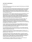
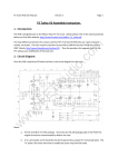
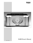
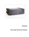
First Watt model F4
Operation and Service Manual
Introduction
Anyone paying attention is aware that First Watt makes unusual amplifiers with
the emphasis on performance at low power levels.
Here’s another one.
The F4 is Class A impedance converting amplifier, having no voltage gain or
feedback. Its input impedance is 47,000 ohms, and its output impedance is
about
0.2 ohms. It is suitable for driving a high sensitivity loudspeaker with the output
voltage of a preamp or other line-level audio source. It is also useful with a less
sensitive loudspeaker in a bi-amped configuration where it takes input from the
output of a conventional amplifier.
As a stereo amplifier with single-ended inputs and outputs, it will deliver up to 25
watts into 8 ohms with a damping factor of 40. It will do 50 watts into 4 ohms,
and as a mono-block amplifier with parallel inputs and outputs, it will do about
100 watts into 2 ohms.
As a mono-block amplifier with balanced inputs and outputs the power output
rating is 100 watts into 8 ohms at 1%, and the damping factor is 20.
The amplifier operates Class A to 25 watts (50 peak), and the distortion is 2nd
and 3rd harmonic in character, rising or declining in linear proportion to the output
power. The amplifier has a direct coupled input and output, with a -0.5 dB rolloff
around .1 Hz and 200 KHz. It does a clean square wave at 100 KHz.
The combination of a simple Class A circuit operated without feedback and the
good objective performance gives us a superb sounding amplifier. The low
distortion, bandwidth extension, and high damping results in midrange clarity,
treble detail, and control on the bottom end.
While these are available from most good solid state amplifiers, the F4 also
brings depth, imaging, midrange warmth and top-end sweetness.
Overall, it is one of the best sounding amplifiers, and if you can live with unity
voltage gain in your amplifier, it is possibly your best choice.
The amplifier is designed for fairly unusual applications:
1) You can drive it directly with a line source such as a preamp.
Using this amplifier presupposes that you have a preamplifier or other source
with adequate voltage and/or loudspeakers sufficiently sensitive to be able to
work with the voltage and gain you have.
You would think offhand that this might be a real problem, but it is my experience
that this is often not the case.
First, you will find that the more sensitive drivers deliver good volume levels
at quite low wattage. My Lowther DX55’s (93 dB/watt) mounted in Alerion
enclosures adequately fill my 11,000 cubic foot listening room with about 5 volts
(the equivalent of a 4 watt amplifier). I can achieve good levels with headroom
to spare with my phono stage or DAC feeding an X1 preamp, which has a
maximum of 14 dB gain.
If I lived in an apartment, I could get complaints from my neighbors.
Thanks to the dutiful efforts of John Atkinson at Stereophile, I have been able
to examine the maximum gain and output voltage of the tube and solid state
preamps he has measured over the last 20 years or so ( www.stereophile.com ).
Virtually all active line stages achieve adequate gain and voltage swing to drive
the above combination. Basically you need a linestage with about 12+ dB gain
and 10+ volt maximum output.
This includes tube products from VTL, Hovland, ARC, Cary, McIntosh, CJ, EAR,
MF, BAT, Lamm, and Rogue. It includes solid state preamps from Pass Labs,
Krell, McIntosh, Levinson, Halcro, Naim, Boulder, Ayre, Bryston, Threshold,
McCormack, Linn, Sutherland, and on and on.
If your loudspeaker is less efficient, then you need more gain from your source
and/or more gain and voltage swing from your linestage. As you go in sensitivity
below 87 dB, you will want to consider 100 watt balanced mono-block use, with
a preamp capable of swinging 14 volts per balanced output and having a gain of
20+ dB.
As your loudspeaker increases in sensitivity, you need less gain and voltage
swing.
You can also use active crossover networks to drive multiple F4’s as shown
below. A number of crossovers on the market incorporate voltage gain and high
voltage swing (a prime candidate being the Pass Labs XVR1, which can swing
the full voltage capability of the F4).
2) You can use it with a low wattage integrated or tube amplifier in a
“biamplied” system
There are a number of popular tube integrated amplifiers on the market, the socalled “Flea Watt”amplifiers which don’t have much juice, but offer a warm “tubey”
sound which is much prized. These amplifiers are good candidates for operation
with an F4 in a setup where the loudspeakers have two separate sets of input
terminals, one for the woofer and one for the midrange/tweeter.
In such a system the F4 is used to drive the bottom end, where it offers superior
damping and higher current, and the flea watt amplifier drives the mid and top
end, unburdened by the effort of driving the woofer but preserving the character
of the tube amp.
It is particularly convenient that the F4 is close to unity gain, which provides close
level matching between the bottom and top. (In the diagram below, it is assumed
that crossover networks are incorporated into the woofer and mid/high end
speakers)
You can take advantage of the same arrangement if you have drivers and you
want to make your own custom passive crossovers:
An alternative arrangement results when you create your own passive crossover
networks using resistors as loads and feeding the results to F4 channels. The
networks behave more ideally driving resistors than the complex impedance
of loudspeakers, and the resistor values can be set over a wide range of
impedances.. The loudspeaker drivers themselves benefit from the direct
connection to the low output impedance of the amplifiers.
3) You can use it with a low wattage integrated or tube amplifier in a standalone system for higher output current
There will be occasions where the loudspeaker load is too low for optimal
performance from a flea watt, and in this case you can consider F4’s for the
purpose of getting as much as 100 watts into 2 ohms per mono-block. In this
arrangement you can also load the flea watt amp (not shown here) with a
resistive or other load which elicits the best performance from it.
Setup
The initial setup of the amplifier is very straight-forward. Place the amplifier
in a well-ventilated location, as it draws about 160 watts during operation and
requires as much opportunity to cool itself as possible. You should be able to put
your hands on the heat sink during operation. If you can’t do this for 5 seconds
or so, they need more ventilation.
On the front panel there are two blue LED lights, one for each channel (or each
half of a mono-block), indicating power to the channel. On the rear panel you
will find a pair of RCA inputs, and XLR balanced input, speaker outputs, a fuse
holder, an AC power receptacle, and on/off switch.
The label will indicate a serial number and also what AC line voltage the amplifier
is set for. If the voltage is 120 VAC, then the fuse value will be a 3AG slow blow
fuse rated at 2.5 amps. If the voltage is 240 VAC, then the fuse will be rated at
1.25 amps. Do not substitute a larger value fuse. Contact First Watt if you have
any questions.
The amplifier can be run in three configurations. There is one way to use the
amplifier in stereo. There are two ways you can run the amplifier as a monoblock, either by paralleling the inputs and outputs for more current and less
distortion, or by driving the two channels from a balanced source.
I’m assuming that you know how to attach the speaker cables to the 5 way output
connectors provided. Please make all the connections with the amplifier power
switch in the OFF position.
Stereo Operation
For two channel operation, input signal is connected to the RCA inputs, ignoring
the XLR input. (Unlike some other designs from First Watt or Pass Labs, there
are no jumpers on the unused XLR inputs.) The output connections to the
loudspeakers are made through the gold plated brass 5 way connectors. The red
(top) connection is positive and the black (bottom) is negative. In this amplifier
the black banded output connectors are connected directly to signal ground.
Mono Balanced Operation
In mono balanced operation, you can achieve up to 100 watts output into an 8
ohm load. The amplifier is driven by a balanced source, either through the two
RCA inputs or the balanced XLR connector. The left channel (as seen from the
front) is presumed to have the positive phase, so the positive input appears either
on the left channel RCA or Pin 2 of the XLR connector. The right channel gets
the negative phase input on its RCA or on Pin 3 of the XLR connector.
Pin 1 of the XLR connector is ground
Pin 2 is positive.
Pin 3 is negative.
If you look carefully at the connector you will see tiny labels next to the pin holes.
No jumpers or shorting plugs are necessary.
The output to the speakers occurs through the top red banded brass connectors
on the two output 5 way binding posts. The left channel (as seen from the front)
has the positive output, and the right channel has the negative. The bottom black
banded connectors are signal ground, and are not used. The positive speaker
lead goes to the left red band, and the negative speaker lead goes to the right
red band.
Mono Parallel Operation
In mono parallel operation, you can achieve up to 100 watts output into a 2 ohm
load. The amplifier is driven by a single-ended source, through the two RCA inputs
in parallel. The easiest way to do this is through a male RCA cable going into one of
the RCA inputs with a jumper between pins 2 and 3 of the XLR input connector, which
parallels the two inputs. This jumper is supplied with the amplifier.
If you look carefully at the connector you will see tiny labels next to the pin holes.
For parallel operation of the two channels as one, you must connect the outputs left
positive to right positive either at the connectors themselves or by “bi-wiring” the
loudspeaker with two sets of cables. Remember that the positive outputs have a red
band.
The black banded output connectors are already connected together to ground, so you
can make this connection externally or not as you please.
With everything connected up and the source equipment powered up first, you
can proceed to turn on the power switch to the amplifier. Turn-on and turn-off
thumps and noise are small in this amplifier, and should not present any hazard
to delicate drivers.
At this point you should be able to listen to music. This amplifier has less gain
than most, but at 15 watts rating, it should not need it. If you need to turn the
gain up on your preamp, then do so. If you can’t get enough gain, then you are
probably using either the wrong speaker or the wrong amplifier. Talk to your
dealer if this is the case.
The power supply of the amplifier is isolated from the chassis and AC earth
ground by a thermistor which connects the circuit ground to the chassis and
earth ground. This helps to prevent ground loops, but the thermistor stands by to
conduct AC line voltage to ground until the fuse blows in case of transformer or
other such failure.
The input impedance is 48 Kohms, and the input capacitance is very low, so
you should find it easy to drive with tube equipment if you like. The amplifier is
largely indifferent to the source impedance of your preamp, so a high source
impedance is not a problem.
The amplifier requires about 1 hour of operation to reach normal operating
temperature, and this warm-up time is appropriate for the most critical listening,
but is not otherwise an issue. The amplifier’s final adjustments were made after
an hour, and the performance difference between 5 minutes and 60 minutes is
significant.
I do not personally see a reason to run the amplifier all the time, but you can
do that if you want to. The power supply capacitors are likely to last about 15
years or so, and while they will slowly dry out just sitting there, they will have a
shorter life span with the amplifier running constantly. Also, at 180 watts it makes
economic sense to shut the amplifier off if you aren’t planning on using it for the
rest of the day.
Again, the heat sinks on this amplifier run fairly hot, and you want to make sure
that they get adequate ventilation. They will run at around 25 degrees C. above
the ambient temperature, which puts them around 50 degrees in the average
listening room. At this temperature you should be able to put your hand on them
for about 5 to 10 seconds or so.
Now the following is for your protection –
Do not defeat the AC line Earth ground connection on the amplifier
power cord. It provides an extra barrier to prevent potential shock
hazard.
Do not replace the fuse with a type other than specified.
Do not operate the amplifier outside in the weather, or in and around
water or anything resembling water. If you spill a drink in the amplifier
or if your dog/cat/child urinates on it, turn it off immediately, unplug it,
and do not operate it until cleaned by a qualified technician.
If something gets loose or rattles around inside or smells funny, or
if you can’t touch the heat sinks for 5 seconds or so, then turn it off,
unplug it from the wall, and contact First Watt.
There are no user serviceable parts inside. Do not open the amplifier,
and if you do anyway, don’t operate it with the cover off. There are
hazardous voltages inside. If you need to change the operating AC
voltage, contact First Watt.
If you have a problem, contact First Watt. We are much happier
helping you solve problems so that we can be certain that it’s done
properly. If you are far away and don’t want to ship the product for
repair, we will assist your technician with information and parts.
Contact:
www.Firstwatt.com [email protected]
Summary of the nominal specifications:
Measured at 120 V AC with a 25 ohm source and an 8 ohm load:
Distortion @ 1 watt
.05% @ 1 KHz
Input Impedance
47 Kohm
Damping Factor
40
Output power stereo 8 ohms
25 watts @ 0.5% THD, 1KHz
Voltage Gain
-0.3 dB
Maximum unclipped output
+/-20 Volts
Maximum output current
5 amps
Frequency response
- .5 dB @ 0.1 Hz, 200 KHz
Noise
50 uV unweighted, 20-20 KHz
Power consumption
180 watts
Fuse
3AG slow blow type, 2.5 Amp for 120VAC
1.25 Amp for 240 VAC
Warranty: Parts and labor for 3 years, not covering shipping costs or
consequential damages.
Copyright 2007 General Amplifier
General Amplifier Inc.
PO BOX 7607
RENO NV 89510-7607
CHANNEL SCHEMATIC
Notes:
Output device bias is approximately .43 amps per device, which measures 200
mV across the .47 ohm source resistors.
All devices are matched for Vgs to .02V.
Cold, bias is adjusted low at 130 mV and readjusted as the amplifier warms up.
The proper value is achieved after 1 hour with the heat sinks at about 50 deg C.
P2 is adjusted for minimal DC offset at output.
POWER SUPPLY SCHEMATIC
Notes:
Thermistors in series with the AC line are also used to select line voltages at 120
VAC or 240 VAC, as seen on the front edge of the PC board layout.
TOP
BOTTOM