1
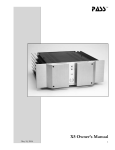
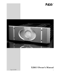
pass
TM
X2.2 Owner’s Manual
Aug
10, 2006
X2.2 Owner’s Manual
1
Introduction
The X2.2 is an ultra high quality non-remote linestage audio
preamplifier with internal power supply. It combines a completely
new circuit topology with traditional construction representing thirty
five years of preamplifier design.
This preamplifier flows from a commitment to create the best
sounding product: a simple circuit with the most natural sonic
characteristics. Derived from US Patent # 5,376,899, the X2.2
integrates power MOSFET and JFET devices in a simple Class A
topology in order to deliver the finest sound possible.
The Super-Symmetric gain circuitry is unique in providing superior
flexibility and performance with both balanced and unbalanced
inputs and outputs, converting one to the other as desired without
extra circuitry and without performance degradation.
The X2.2 minimizes the number of components in the signal path,
and yet retains exemplary objective performance specifications. It
pushes the edge of the art in exploring how much subjective quality
is obtainable with a new but very elementary gain stage.
The X2.2 employs a patented new type of volume control that offers
significantly better performance than seen before in an electronic
control. It provides over 60 dB of range, large voltage swing and
very good measured performance. The distortion and noise is at
1/10 and the dynamic range 100 times the previous state of the art
in active attenuation. Most importantly it is subjectively outstanding;
better than any potentiometer we have evaluated.
The X2.2 may be factory upgraded to the X2.5 which will convey
several operational functions and remote control which are absent
from the X2.2. The upgrade will also change the front panel display
to the more informative vacuum fluorescent alpha-numeric display.
Very few people are involved in the production of this product. I
supervise all phases of the construction, and I test each preamplifier
myself. If you have questions, comments, or problems, please feel
free to contact me directly.
Thank you for purchasing this preamplifier. It is my sincere hope
that you will enjoy its sound as much as I do.
Wayne Colburn
Vice President, Design
X2.2 Owner’s Manual
2
Setup
The preamplifier has four sets of input connections, both singleended and balanced output connections, and a separate tape loop.
The preamplifier’s voltage and current rating are indicated by affixed
tag on the bottom of the preamplifier. It will indicate either 240
volts, 220 volts, 120 volts, or 100 volts. A 0.5 amp 3AG slow blow
fuse is provided with 100-120 volt units, and a 0.25 amp slow blow
fuse is provided with 220-240 volt units. The frequency rating of the
power supply is 50 to 60 Hz in all cases. The preamplifier typically
draws less than 30 watts during operation. Please verify that the
indicated voltage requirement of this preamplifier is consistent with
the voltage at your location.
We have provided a standard IEC AC power cord that fits into the
IEC line receptacle at the rear of the preamplifier chassis. The
preamplifier is equipped for operation with an earth ground provided
by the user’s AC outlet. Do not defeat this ground. The circuit
ground of the preamplifier is connected to earth and power ground
through a power thermistor, which gives a ground connection for
safety but helps avoid ground loops.
There are a total of four inputs and a separate tape loop. Two of
the four inputs can be used single-ended or balanced. The other two
inputs are single-ended only. The tape loop has both single-ended
and balanced inputs and outputs. Balanced inputs and outputs are
via XLR connectors. Single-ended inputs and outputs are via RCA
connectors. On the XLR connectors, pin 1 is grounded, pin 2 is the
positive signal, and pin 3 is the negative signal. Left channel RCA
connectors are marked with “L” from below. Right channel RCA
connectors are marked with “R” from below. Balanced XLR inputs
and outputs are marked with “L” for left and “R” for right channel.
If your signal source is unbalanced, input will occur through the
RCA input connector, which is in parallel with the XLR connections
1 and 2. When single-ended inputs are used on input 1 and input
2, a shorting plug is provided between pins 1 and 3 of the XLR
connection, shorting the negative input to ground, and providing
optimal performance.
The unbalanced input impedance of the preamplifier is 33 kOhms.
In balanced mode, the input impedance is higher, with a differential
impedance of at least 66k Ohms.
Next to the inputs on the rear panel, the preamplifier offers tape
inputs through both XLR and RCA connectors. This output is a
direct connection to inputs 1, 2, 3, and 4 when they are selected from
X2.2 Owner’s Manual
3
the front panel. Input 5 (TAPE IN) is deliberately not available
through the tape output connection. The tape input is designated
for use with a tape recorder if you have one, and we have arranged
that it will not place its output on the tape out, which will prevent
you from accidentally creating a feedback connection with your tape
machine.
The main outputs are located at the left-hand side (viewed from the
rear) of the rear panel, two male XLR connectors, and two RCA
connectors, “R” (right) and “L” (left). The RCA connectors’ ground
is in parallel with pin 1 of the XLR outputs and the RCA hot is fed
from an independent summing junction that maximizes the X circuit
benefits. The RCA, single-ended outputs are buffered from the balanced
outputs. You may use both the single ended and balanced outputs at the
same time. On the XLR, pin 1 is ground, pin 2 is positive, and pin 3 is
negative.
The rear 5-way binding post can be used to turn on any X series
power amplifier.
Description of Operation
In application the X2.2’s front panel controls and simple LED
displays are quite straight forward, and intuitive. We encourage you
to become familiar with their operation prior to establishing any
input connections with this unit. Experience indicates that engaging
in a few minutes of exploration and playtime will add much to your
ultimate enjoyment of this exceptional Pass Labs product.
The front panel of the X2.2 has all its control functions moderated
by five momentary pushbuttons. From left to right these buttons are
labeled input, tape, volume (down), volume (up) and mute.
The input button has four associated blue LED’s located directly
above the input switch. When the uppermost blue LED is lit it
indicates that you have selected input number 1. With an additional
push of the input selector button the second uppermost LED will
be on, indicating you have selected input number 2. So it goes, the
same pattern follows with input 3 and 4. An additional push of
the input selection button when you are on input 4 will cycle the
preamplifier back to input 1.
The second button from the left controls the tape loop, a blue LED
directly above this switch indicating the status of this particular
function. When the tape loop is active, this LED will be lit.
Immediately to the right of the tape loop control are the two volume
X2.2 Owner’s Manual
4
control buttons, indicated by up arrows (^) and down (v) arrows.
Above the volume controls are two vertical arrays of 4 LEDs each.
This indicator is likely different from what you are accustomed to.
We think you will appreciate how easy it is to read from a distance.
The left most LED array is decade and the right most array is range.
Associated with the volume control is one additional light and a
function control button labeled as “MUTE”. In the very lowest
volume setting there will be no output and the “Mute” indicator
light will be lit. Immediately to the left of the lit “MUTE” indicator
the lowermost LED in the range column will also be lit. None of
the decade LED’s will be lit, at this time. As you step the volume
upward using the up (^) button additional LED’s in the range column
will light and the mute LED will extinguish. When you reach the top
of the range, the first decade LED will become illuminated, and the
range LED will drop back to its lowest indicated setting. And so it
goes; think of this as a counting system in base 5.
Activating “MUTE” while at any volume level does not lose the
chosen volume setting. When deactivating mute the X2.2 will be
returned to the last stored volume level.
Should you wish to upgrade the 2.2’s status to a full function remote
control preamplifier, this may be acomplished at the factory. With
additional circuitry and new front panel the X2.2 may be turned
into an X2.5 This upgrade adds an informative vacuum fluorescent
display, balance control, display brightness, mono, unity function,
gain setting and remote control capability.
A rear mounted pair of five-way binding posts are intended to
control the on/off function of our own X series power amplifiers
from the X2.2 front panel. This function is activated through
software by simultaneously pushing the extreme left control button
(INPUT) and the extreme right (MUTE) control button. When
the preamp mode “Amp” is selected it allows the user to switch
a nominal 12 volts DC at maximum draw of 50 milliamps to the
rear panel red and black five-way binding posts. In some instances
this voltage may have the ability to control products from other
manufacturers, but we by no means have comprehensive listing of
their compatible features. If you have questions about compatibility
your service technician and dealer are an excellent source of
information. For connection to other Pass Labs products please
consult the owner’s manual for specific instructions.
The electronic volume control allows approximately 60 dB range. In
this manner tracking of the volume of the two balanced channels is
possible with accuracy unavailable on any ordinary volume control,
X2.2 Owner’s Manual
5
assuring precise level steps and high common-mode rejection in
balanced circuits. Wayne Colburn’s exceptional volume control, in
conjunction with the unique LED display, gives the user the ability
to replicate volume levels with absolute accuracy in steps of roughly
3dB.
Product Philosophy
1) Circuit simplicity and a minimum number of components is a key
element. The fewer parts in series with the signal path, the better.
Adding more parts and gain stages may improve measured specs,
but will seldom improve the perceived sonic quality or reliability of a
product.
2) The characteristic of gain devices and their specific use is
important. Individual variations in performance between like devices
are important, as are differences in topological usage. All signal
bearing devices contribute to the degradation, but there are some
different characteristics that are worthy of attention. For example,
smooth low order nonlinearities are additive in quality, bringing false
warmth and coloration, while abrupt high order nonlinearities add
harshness and false brightness.
3) Maximum intrinsic linearity is desired. This is the performance
of the gain stages before feedback is applied. Experience suggests
that feedback is a subtractive process; it removes information from
the signal. In many older designs, poor intrinsic linearity has been
corrected by large application of feedback, resulting in loss of
warmth, space, and detail. The trick is to get good performance
without this excessive reliance on feedback.
The art of high end audio design lies in the approach of combining
these elements to get high reliability and simplicity, high quality
measured performance, and high quality subjective performance. It
takes imagination and hard work to get as much of these as possible
at once without trading them off against each other.
Other Design Comments
We recommend the use of the balanced output mode where possible.
It will retain the character of the input mode, but offers less
distortion, less noise, more gain, and more voltage swing, without
compromising the sound.
With balanced operation, the common-mode rejection of the
preamp reflects the intrinsic common-mode rejection of the
topology, the matching of the gain devices, and the matching of
the attenuator channels. In this case we have been able to keep
X2.2 Owner’s Manual
6
the total mismatch to about .1%, for a common-mode rejection of
approximately -60 dB.
The input system of the preamplifier will exhibit full common-mode
noise rejection with passive balanced sources, where the negative
input is connected to ground at the source through the appropriate
source impedance. This allows adaptation of unbalanced sources to
balanced operation with passive cable connections in a manner that
achieves the noise rejection of active balanced sources.
The use of a micro-controller allows all of the preamplifier functions
to be repeatable and accurately controlled. The micro-processor
only controls the functions of the preamplifier. At no time does
any of the input or output signal come into contact with the digital
control signals. The digital circuits are powered by a power supply
that is completely separate from the analog supply. Should it ever be
necessary to update the software that controls the functioning of the
preamp only the socketed micro-processor need be changed.
The power supply for the X2.2 consists of a toroidal power
transformer delivering an unregulated +/- 45 volts which is actively
regulated before feeding passive filtering and powering the constant
current sources which bias the gain stages. Each channel has its own
regulation. The power supply noise reaching the circuit is on the
order of one microvolt, and the little of that which gets through the
circuit is rejected at the output in a balanced system. The relays and
control systems are regulated independently, and all digital circuitry is
isolated from the power supply.
Muting relays, which delay connection during turn-on and shut off
the output when insufficient power supply is available to maintain
regulation, guard the output of the preamplifier. The preamplifier
is designed to run constantly, and will exhibit optimum measured
performance within about 10 hours of turn-on.
The X2.2 consists of a single chassis.
X2.2 Owner’s Manual
7
X2.2 Specifications
Gain, Balanced:
selectable 4 / 14dB
Gain, single-ended:
selectable 4 / 14 dB
Freq. Response:
-3 dB @ 2 Hz, -3 dB at @ 100K Hz
Distortion @ 1KHZ: < .1 % THD, typically .003% @ 2 volts
Maximum Output:
10 volts rms. bal out, 7 volts rms. unbal
Output Impedance:
200 ohms unbal, 750 ohms balanced
Input Impedance:
33K Ohm unbal, 66K Ohm balanced
CMRR:
typ. -55 dB, 1KHz
Crosstalk:
typ. -85 dB, 1KHz
Output Noise floor:
< -125 dBV, 20Hz to 20KHz
External amp turn on: 12 volts DC 50 mA continuous
Power Consumption: 35 watts
Dimensions:
17” W x 11.5 “D
Shipping Weight:
28 Lbs in packing
x 3.5”H
Pass Laboratories Inc.
P.O. Box 219,
24449 Foresthill Rd.,
Foresthill, CA 95631
Tel: 530.367.3690, Fax: 530.369.2193, www.passlabs.com
© 2006 Pass Laboratories Inc.
“Pass”, “pass”, “Pass Labs”, “Pass Laboratories”, Supersymmetery”,
“Aleph”, and “Zen” and are all registered trademarks of Pass
Laboratories, Inc., and all rights thereto are protected by law.
X2.2 Owner’s Manual
8
Warranty Information
Please check with the factory-authorized distributor in the country you are
purchasing this product for specific warranty information.
All Pass Laboratories products purchased from an authorized Pass Laboratories dealer in North America are covered by a transferable, limited 3-year
warranty. This warrantee includes all parts and labor charges incurred at the
repair facility in addition to return shipping to the domestic customer, exclusive of subsequent damages. Damage due to physical abuse is specifically
not covered under this warranty.
For this warranty to apply the customer is responsible for returning the
product unmodified to the factory within the warranty period. The customer
assumes all responsibility for shipping and insurance to the factory or a factory specified repair facility. The conditions and stipulations of this Pass
Laboratories warranty only applies to units sold new in North America.
Non-North America customers should consult with their original Pass Labs
dealer or distributor for warrantee repair instruction prior to contacting the
factory or shipping product for repair.
Non-North American product must be returned to the country of origin for
warrantee service. Foreign distributors are only required to offer warranty
service on Pass Laboratories product that they have imported.
Please note: Conditions of warranty service and customer rights for product
purchased outside the United States may vary depending upon the distributor and local laws. Please check with your local distributor for specific rights
and details.
Any modifications to Pass Laboratories products that have not received
written factory approval nullify all claims and void the warrantee. Should a
modified product be returned to the factory for repair the owner will be required to pay all necessary charges for the repair in addition to those charges
required to return the product to it’s original configuration.
In the case of safety issues, no product shall be returned to the customer
without those safety issues being corrected to the most recent accepted
standards.
Removal or alteration of original Pass Labs serial numbers voids the factory
warranty. Product with altered or missing serial numbers will be suspected
as counterfeit product.
Pass Laboratories will not repair or in any way indemnify any counterfeit or
cloned product.
Pass Laboratories does not offer products in voltages intended for international markets either to authorized Pass Labs dealers or to third parties
located in the United States or Canada.
X2.2 Owner’s Manual
9
For your protection please
read the following:
Water and moisture: Electrical devices should not be used near
water ( as per example, near a bathtub, washbasin, kitchen sink,
laundry tub, wet basement or swimming pool ). Care should be
taken such that objects do not have the opportunity to fall, and that
liquid is never spilled onto or into the device enclosure through
openings.
Power Sources: An electrical device must be connected to a mains
power source in strict accordance with the supplied product owner’s
manual. Please verify that the AC mains voltage specified in the
product manual matches those requirements indicated on the unit
and the AC voltage provided to your location by the power company.
Grounding: Adequate precautions should be taken so that the
grounding provisions built into an electrical product are never
defeated.
Power Cords: Pass Laboratories provides a power supply cord that
meets all legislated requirements for the market in which the product
was originally sold. If you choose to substitute an after-market
product we urge you to choose one that is fully safety rated by the
necessary local authority.
Power Cord Protection: Power supply cords should be routed so
that they are not likely to be walked on, abraded, or pinched by items
placed on or against them, paying particular attention to cords where
they enter plugs or exit from a device. Never under any circumstance
insert a cut or damaged power cord into a mains power socket.
Power and Signal: Cables should never be connected /
disconnected with equipment powered up. Failure to heed this
warning may damage or destroy equipment.
Ventilation: Power-amplifiers run hot, but you should be able to
place your hands on them without discomfort. You must allow for
this heat in installation, by providing for free air circulation around
the product. Electronics should not be subjected to sources of
excessive radiant heat. Excessive heat can shorten the life of the
product and may cause the electronics to self-protect and shut down.
Servicing: To reduce the risk of fire, electrical shock or other
injuries, the user should not attempt to service the device beyond
that which is described in the operating instructions. All other
servicing must be referred to qualified service personnel.
X2.2 Owner’s Manual
10